EP1979856B1 - Enhanced navigational tools for comparing medical images - Google Patents
Enhanced navigational tools for comparing medical images Download PDFInfo
- Publication number
- EP1979856B1 EP1979856B1 EP07762774.3A EP07762774A EP1979856B1 EP 1979856 B1 EP1979856 B1 EP 1979856B1 EP 07762774 A EP07762774 A EP 07762774A EP 1979856 B1 EP1979856 B1 EP 1979856B1
- Authority
- EP
- European Patent Office
- Prior art keywords
- image
- images
- nodule
- location
- line
- Prior art date
- Legal status (The legal status is an assumption and is not a legal conclusion. Google has not performed a legal analysis and makes no representation as to the accuracy of the status listed.)
- Active
Links
- 239000003550 marker Substances 0.000 claims description 23
- 210000004072 lung Anatomy 0.000 claims description 14
- 238000000034 method Methods 0.000 claims description 8
- 230000000007 visual effect Effects 0.000 claims description 8
- 239000003086 colorant Substances 0.000 claims description 6
- 206010054107 Nodule Diseases 0.000 description 29
- 238000002591 computed tomography Methods 0.000 description 22
- 210000003484 anatomy Anatomy 0.000 description 4
- 238000009877 rendering Methods 0.000 description 4
- 230000002159 abnormal effect Effects 0.000 description 3
- 230000002123 temporal effect Effects 0.000 description 3
- 230000002792 vascular Effects 0.000 description 3
- 238000012800 visualization Methods 0.000 description 3
- 230000003213 activating effect Effects 0.000 description 2
- 210000004556 brain Anatomy 0.000 description 2
- 230000000052 comparative effect Effects 0.000 description 2
- 239000002131 composite material Substances 0.000 description 2
- 238000002059 diagnostic imaging Methods 0.000 description 2
- 230000002452 interceptive effect Effects 0.000 description 2
- 238000002595 magnetic resonance imaging Methods 0.000 description 2
- 238000002603 single-photon emission computed tomography Methods 0.000 description 2
- SMLNREUXXJESLR-BYPYZUCNSA-N (2r)-2-(ethylamino)-3-sulfanylpropanoic acid Chemical class CCN[C@@H](CS)C(O)=O SMLNREUXXJESLR-BYPYZUCNSA-N 0.000 description 1
- 206010028980 Neoplasm Diseases 0.000 description 1
- 230000004397 blinking Effects 0.000 description 1
- 238000003384 imaging method Methods 0.000 description 1
- 230000004807 localization Effects 0.000 description 1
- 230000036210 malignancy Effects 0.000 description 1
- 238000009206 nuclear medicine Methods 0.000 description 1
- 230000001575 pathological effect Effects 0.000 description 1
- 230000002685 pulmonary effect Effects 0.000 description 1
- 238000011002 quantification Methods 0.000 description 1
- 230000011218 segmentation Effects 0.000 description 1
- 239000007787 solid Substances 0.000 description 1
Images

Classifications
-
- G—PHYSICS
- G06—COMPUTING; CALCULATING OR COUNTING
- G06T—IMAGE DATA PROCESSING OR GENERATION, IN GENERAL
- G06T7/00—Image analysis
- G06T7/0002—Inspection of images, e.g. flaw detection
- G06T7/0012—Biomedical image inspection
- G06T7/0014—Biomedical image inspection using an image reference approach
- G06T7/0016—Biomedical image inspection using an image reference approach involving temporal comparison
-
- G—PHYSICS
- G06—COMPUTING; CALCULATING OR COUNTING
- G06T—IMAGE DATA PROCESSING OR GENERATION, IN GENERAL
- G06T19/00—Manipulating 3D models or images for computer graphics
-
- G—PHYSICS
- G16—INFORMATION AND COMMUNICATION TECHNOLOGY [ICT] SPECIALLY ADAPTED FOR SPECIFIC APPLICATION FIELDS
- G16H—HEALTHCARE INFORMATICS, i.e. INFORMATION AND COMMUNICATION TECHNOLOGY [ICT] SPECIALLY ADAPTED FOR THE HANDLING OR PROCESSING OF MEDICAL OR HEALTHCARE DATA
- G16H30/00—ICT specially adapted for the handling or processing of medical images
- G16H30/20—ICT specially adapted for the handling or processing of medical images for handling medical images, e.g. DICOM, HL7 or PACS
-
- G—PHYSICS
- G16—INFORMATION AND COMMUNICATION TECHNOLOGY [ICT] SPECIALLY ADAPTED FOR SPECIFIC APPLICATION FIELDS
- G16H—HEALTHCARE INFORMATICS, i.e. INFORMATION AND COMMUNICATION TECHNOLOGY [ICT] SPECIALLY ADAPTED FOR THE HANDLING OR PROCESSING OF MEDICAL OR HEALTHCARE DATA
- G16H30/00—ICT specially adapted for the handling or processing of medical images
- G16H30/40—ICT specially adapted for the handling or processing of medical images for processing medical images, e.g. editing
-
- G—PHYSICS
- G06—COMPUTING; CALCULATING OR COUNTING
- G06T—IMAGE DATA PROCESSING OR GENERATION, IN GENERAL
- G06T2200/00—Indexing scheme for image data processing or generation, in general
- G06T2200/24—Indexing scheme for image data processing or generation, in general involving graphical user interfaces [GUIs]
-
- G—PHYSICS
- G06—COMPUTING; CALCULATING OR COUNTING
- G06T—IMAGE DATA PROCESSING OR GENERATION, IN GENERAL
- G06T2207/00—Indexing scheme for image analysis or image enhancement
- G06T2207/10—Image acquisition modality
- G06T2207/10072—Tomographic images
-
- G—PHYSICS
- G06—COMPUTING; CALCULATING OR COUNTING
- G06T—IMAGE DATA PROCESSING OR GENERATION, IN GENERAL
- G06T2207/00—Indexing scheme for image analysis or image enhancement
- G06T2207/10—Image acquisition modality
- G06T2207/10116—X-ray image
-
- G—PHYSICS
- G06—COMPUTING; CALCULATING OR COUNTING
- G06T—IMAGE DATA PROCESSING OR GENERATION, IN GENERAL
- G06T2207/00—Indexing scheme for image analysis or image enhancement
- G06T2207/30—Subject of image; Context of image processing
- G06T2207/30004—Biomedical image processing
- G06T2207/30061—Lung
- G06T2207/30064—Lung nodule
-
- G—PHYSICS
- G06—COMPUTING; CALCULATING OR COUNTING
- G06T—IMAGE DATA PROCESSING OR GENERATION, IN GENERAL
- G06T2219/00—Indexing scheme for manipulating 3D models or images for computer graphics
- G06T2219/028—Multiple view windows (top-side-front-sagittal-orthogonal)
-
- G—PHYSICS
- G06—COMPUTING; CALCULATING OR COUNTING
- G06V—IMAGE OR VIDEO RECOGNITION OR UNDERSTANDING
- G06V2201/00—Indexing scheme relating to image or video recognition or understanding
- G06V2201/03—Recognition of patterns in medical or anatomical images
-
- G—PHYSICS
- G16—INFORMATION AND COMMUNICATION TECHNOLOGY [ICT] SPECIALLY ADAPTED FOR SPECIFIC APPLICATION FIELDS
- G16H—HEALTHCARE INFORMATICS, i.e. INFORMATION AND COMMUNICATION TECHNOLOGY [ICT] SPECIALLY ADAPTED FOR THE HANDLING OR PROCESSING OF MEDICAL OR HEALTHCARE DATA
- G16H40/00—ICT specially adapted for the management or administration of healthcare resources or facilities; ICT specially adapted for the management or operation of medical equipment or devices
- G16H40/60—ICT specially adapted for the management or administration of healthcare resources or facilities; ICT specially adapted for the management or operation of medical equipment or devices for the operation of medical equipment or devices
- G16H40/63—ICT specially adapted for the management or administration of healthcare resources or facilities; ICT specially adapted for the management or operation of medical equipment or devices for the operation of medical equipment or devices for local operation
Definitions
- This relates to navigational tools to facilitate the comparison of two temporally related medical images on a computer-driven display.
- medical images is used broadly herein to refer not only to actual images such as x-rays, CT axial sections, MRI images, sonograms, mammograms and the like, but also to representations and/or abstractions of such images as in the case of a display of regions of interest on an anatomical background map.
- CT chest computer tomography
- the principles of the invention may, however, be applied in the comparison of any two medical images of the same features.
- US 2003/0095697 A1 discloses a system for rendering anatomical information of a body from tomographic data obtained from a digital imaging apparatus.
- the system comprises a first portion of a display for rendering a sequence of two-dimensional tomographic sections obtained from the tomographic data and a second portion of the display for rendering a first volumetric view of the body, wherein the first volumetric view includes a third dimension acquired from the sequence of two-dimensional tomographic sections.
- the system further comprises a third portion of the display for rendering a second volumetric view of a selected feature shown in the section then being rendered on the first portion or the second portion of the display.
- US 2001/0002934 A1 discloses an image display apparatus for displaying two or more images of an identical object to be compared.
- the image display apparatus comprises an image display means for displaying the two or more images thereon and position matching means for arranging the two or more images in a row or a column so that positions of a structural feature area of the identical object in the two or more images are aligned horizontally or vertically.
- JP 2005-33421 discloses a diagnostic imaging support system comprising an image data reading means for reading image data showing a subject, a suspected abnormal shadow extracting means for extracting a suspected abnormal shadow from the image of the subject, and a display controlling means for controlling a display means such that a marker indicating the suspected abnormal shadow is shown in the image of the subject.
- the diagnostic imaging support system further comprises an operation means for receiving an operation to select the marker on the display means and a storing means for storing the selected marker. The stored selected marker can later be retrieved from the storing means and again shown on the display means together with an image of the subject.
- US 2003/0016850 A1 discloses a graphical user interface device for comparing body images.
- the graphical user interface device comprises a display coupled to a microprocessing device and a memory device, wherein electronic representations of a first body image taken at t 1 along a first plane and a second body image taken at t 2 along the first plane are stored in the memory device and displayed on the display.
- the graphical user interface device further comprises an electronic representation of at least one composite image of the first body image and the second body image.
- US 2004/0081342 A1 discloses an image processing apparatus comprising input means for inputting at least two medical images taken at different points in time, difference image generating means for generating a difference image by positioning two medical images input by the input means and subjecting image signals at corresponding coordinate points to difference processing, and a difference image storing means for storing the difference image generated by the difference image generating means in a storing medium.
- the image processing apparatus further comprises a reference difference value determining means for determining a reference difference value in the difference image stored by its difference image storing means, a state selecting means for allowing a user to select a state of shadow change to serve as an indicator of interpreting the difference image generated by the difference image generating means, and a difference image processing means for processing the difference image based on the reference difference value determined by the reference difference value determining means and the state of shadow change selected by the state selecting means.
- An output means outputs the difference image processed by the difference image processing means.
- the present invention is directed to a navigation tool that facilitates this matching and comparative visualization process.
- the tool provides a side-by-side computer-driven display of two temporally related medical images of the same region of a patient.
- a means for locating corresponding nodules in each of the images is provided.
- a plurality of lines extend between the images, at least a first line beginning at a nodule at a first location in a first image and ending at a corresponding nodule at a corresponding location in the second image and at least a second line extending from a nodule found at a second location in one of the images toward a corresponding second location in the other image where no corresponding nodule is found.
- the second line indicates a nodule found in one image but not the other. If the nodule is found in the first image in time but not the second, it has disappeared; and if the nodule is found in the second image in time but not the first, it is new.
- the first and second lines have different visual appearances. For example, they have different colors.
- the navigational tool also includes a scroll bar alongside the display of medical images.
- a scroll bar On the scroll bar are a series of markers, each marker corresponding to one of the plurality of lines that extend between the images and preferably being aligned with that line.
- the visual appearance of the markers varies with the lines with which they are associated.
- they may have the same color as the line and that color may vary depending on whether the line joins nodules in the two images or the nodule is found only in the first image in time or the second image in time.
- the marker can be a line whose length varies with the lines between the two images.
- the marker line may be longest in the case where the associated line joins two nodules in the two medical images and the marker line may be only half that length where the line is connected to only one nodule.
- the position of the shorter marker line may be varied to indicate whether the nodule it connects to is in the first image or the second image.
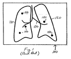
- FIG. 1 depicts a display 100 of nodules on a lung anatomical background map constructed to facilitate localization and comparative visualization of the nodules.
- key anatomical structures can be extracted from the original x-rays, CT axial sections and the like and represented in a map in several ways. For example, one can project the anatomical structures onto a 2D plane and create a projection 2D map. Another method, as shown here, is to create a line drawing type of map to represent the lung anatomy. The border of the lungs is represented by closed lines 110, 120. Other anatomical background such as the airway and vascular structures are represented by dark lines 130.
- discs 140 The approximate location of nodules relative to the background structures represented by lines 110, 120, 130 is shown by discs 140.
- the discs are brightly colored, e.g., red, to make them stand out in the display.
- the discs could blink or be emphasized in other ways.
- the size of the disc may vary in proportion to the size of the nodule.
- Fig. 1 has been successfully implemented in computer-aided nodule analysis software such as the assignee's ImageChecker® CT software and is referred to as a "nodule navigation map.”
- Illustrative apparatus for the display of such map is described in detail in assignee's US Patent 6,925,200 for "Graphical User Interface for Display of Anatomical Informations".
- assignee's US Patent 6,925,200 for "Graphical User Interface for Display of Anatomical Informations”.
- each disc is advantageously hot-linked to the CT section that contains an image of the nodule it represents so that by aligning an indicating device such as a cursor with a nodule and activating a selection device such as a mouse, the radiologist can access the corresponding CT section.
- the map provides a convenient way for the radiologist to access the individual CT section that contains an image of the nodule.
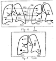
- FIG. 2 depicts a display 200 of two such images side-by-side.
- the images depict nodules on a lung anatomical background map generated by nodule analysis software running on a computer system.
- the image on the right hand side is later in time.
- the border of the lungs is represented by closed lines 210, 220.
- Other anatomical background such as the airway and vascular structures are represented by dark lines 230.
- the approximate location of nodules relative to the background structures is shown by discs 240.
- the border of the lungs is represented by closed lines 250, 260 and other anatomical background by dark lines 270.
- the approximate location of nodules relative to the background structures is represented by discs 280.
- the software determines which nodules in one image correspond to those in the other image and generates a plurality of lines 290 that extend between the images.
- some lines 291-293 begin at a disc 240 in the first image and terminate at a disc 280 at the corresponding location in the second image.
- Another line 294 extends from a disc 240 in the first image toward the corresponding location in the second image but does not terminate at any disc in the second image.
- This line is associated with a feature found in the first image but not found in the second because it has disappeared.
- Another line 295 extends from a disc 280 in the second image toward the corresponding location in the first image but does not start from any disc in the first image. This line is associated with a feature found in the second image but not found in the first image because it is new.
- lines 290 can have different colors or other distinguishing characteristics.
- lines 291-293 linking discs in both images might be blue
- line 294 relating to a disc that is not found in the second image might be green
- line 295 relating to a newly found disc in the second image might be red.
- Fig. 2 may also be condensed into a display in a single image of the lungs in which different marker symbols are used to distinguish nodules that appear in both temporal images from nodules that appear only in the first image or only in the second image.
- Fig. 3 is a display 300 of such nodules on a lung anatomical background map. Again, the border of the lungs is represented by closed lines 310, 320 and the airway and vascular structure by lines 330. Nodules that are found in both sets of temporal images are represented by solid black discs 341, 342, 343.
- Nodules that are found in the first image but not the second are represented by a disc 344 of another color such as green; and nodules that are found in the second image but not in the first are represented by a disc 345 of still another color such as red.
- a disc 344 of another color such as green
- a disc 345 of still another color such as red
- Other visually distinguishing characteristics may be used to distinguish the different kinds of nodules.
- disc 344 is represented by a small circle and disc 345 is represented by a large circle..
- the size of the disc can be in proportion to the size of the nodule.
- New nodules might be indicated by a blinking disc.
- changes in size of the nodules may also be advantageous to indicate changes in size of the nodules by color coding or other arrangements. For example, numbers might be displayed alongside the disc indicating the percent change in the size of the nodule in the second image relative to the first. Plus and minus signs could be used to show the direction of change or colors such as red and green.
- the navigational tool also includes a scroll bar on one side or the other of the display of medical images.
- Fig. 4 depicts a display 400 of two temporally related images with a scroll bar 401 along the right-hand side.
- the temporally related images are the same as those of Fig. 2 . Accordingly, they have been numbered the same and will not be described further.
- Scroll bar 401 comprises a first set of up and down scroll buttons 402, a display bar 403, a set of left and right scroll buttons 404 and a cursor 405.
- On the scroll bar are a series of horizontal lines or markers 406-410, each of which corresponds to one of the plurality of lines that extend between the pair of medical images to the left of the scroll bar.
- each marker is aligned with its corresponding line between the pair of images. Since each nodule in the images also is found in one of the CT axial sections, the markers on display bar 403 are also a visual display of the vector of CT axial slice numbers that contain a nodule.
- the visual appearance of the markers varies with the lines with which they are associated.
- they may have the same color as the line and that color may vary depending on whether the line joins features in the two images or the feature is found only in the first image in time or the second image in time.
- the marker can be a line whose length varies with the lines between the two images.
- the marker line may be longest where the associated line joins two features in the two medical images; and as in the case of markers 408, 410, the marker line may be only half that length where the line is connected to only one feature.
- the position of the shorter marker line may be varied to indicate whether the feature it connects to is in the first image by left-adjusting the marker as in the case of marker 408 or in the second image by right-adjusting the marker as in the case of marker 410.
- Fig. 5 depicts such a display where the left hand image is a map 520 that locates the nodules on the lung anatomical map and the right hand image is the CT axial section 530 that displays an image of the nodule selected by the cursor 405.
- map 520 is user selectable. It might be the map of the nodules in the more recent stack of CT axial sections, or the map of the nodules in the older stack, or a composite of the two maps such as that shown in Fig. 3 .
- the up/down scroll buttons 402 enable the user to step the display of CT sections in display 530 from one section containing a nodule to the next section containing a different nodule. Specifically, with each click of an up or down scroll button 402, display 530 goes from the display of a CT section containing one nodule to display of the CT section containing the next nodule.
- Left and right scroll buttons 404 allow the user to navigate through the entire stack of CT axial sections one at a time. Each click of a left or right button changes the display 530 to display the next axial section down or up in the stack. Thus, the user is able to view the CT sections immediately adjacent to the section in which the image of the nodule appears.
- the left and right control buttons can be used to select whether the axial section that is displayed comes from the older stack of CT sections or the newer stack.
- Additional controls may also be provided to allow the user to select the images that appear alongside the scrollbar. For example, some users may prefer to have the map displayed immediately adjacent the scrollbar instead of the axial section as in Fig. 5 . The user may also wish to compare an axial section in the more recent image stack with the corresponding axial section in an earlier image stack and may want to suppress display of the map to allow the display of the two sections side-by-side.
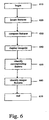
- Fig. 6 is a flowchart for the software program that generates the displays of Figs. 2-6 .
- the software program comprises a set of computer instructions stored in a computer readable medium available to the computer that generates these displays.
- the program begins a step 610 with the data representing a pair of temporally related medical images.
- the images may be actual images such as x-rays and the like or abstractions derived from such images such as projection maps or anatomical maps.
- the program locates features or regions of interest in each of the first and second medical images. For example, in the case where the medical images are of the pulmonary region, the features might be nodules.
- the program compares the two images to identify corresponding features at substantially the same location in each image.
- Corresponding features found in both medical images are identified at step 650; and features found in only one medical image are identified at step 660.
- the corresponding features may be identified by a line connecting the corresponding features in both images and the features found in only one image may be identified by a line extending from the feature in the image where it is found toward the other feature.
- the features found in both images may be marked on the displayed image in one fashion while the features found in only one image may be marked in a different fashion.
Description
- This relates to navigational tools to facilitate the comparison of two temporally related medical images on a computer-driven display. The term medical images is used broadly herein to refer not only to actual images such as x-rays, CT axial sections, MRI images, sonograms, mammograms and the like, but also to representations and/or abstractions of such images as in the case of a display of regions of interest on an anatomical background map. The invention is particularly useful in the comparison of chest computer tomography (CT) scans of the same patient taken at different times and will be described in that context. The principles of the invention may, however, be applied in the comparison of any two medical images of the same features.
- It is common clinical practice to acquire chest CT scans of the same patient at different times and compare them to monitor nodular structures. By comparing the potentially pathological nodular structures present in these scans, vital diagnostic/treatment information can be obtained.
- In today's clinical practice, the tracking and comparing of nodules across multiple temporal CT scans is a very tedious process. Modem CT scans produce image stacks of hundreds of axial image slices. While numerous tools exist for matching the major anatomical features of the lungs that are visible in both stacks, it is extremely time-consuming to find and match the corresponding nodules in the two stacks of hundreds of axial slices.
-
US 2003/0095697 A1 discloses a system for rendering anatomical information of a body from tomographic data obtained from a digital imaging apparatus. The system comprises a first portion of a display for rendering a sequence of two-dimensional tomographic sections obtained from the tomographic data and a second portion of the display for rendering a first volumetric view of the body, wherein the first volumetric view includes a third dimension acquired from the sequence of two-dimensional tomographic sections. The system further comprises a third portion of the display for rendering a second volumetric view of a selected feature shown in the section then being rendered on the first portion or the second portion of the display. -
US 2001/0002934 A1 discloses an image display apparatus for displaying two or more images of an identical object to be compared. The image display apparatus comprises an image display means for displaying the two or more images thereon and position matching means for arranging the two or more images in a row or a column so that positions of a structural feature area of the identical object in the two or more images are aligned horizontally or vertically. -
JP 2005-33421 - The article "Quantitative Comparison of Automatic and Interactive Methods for MRI-SPECT Image Registration of the Brain Based on 3-Dimensional Calculation of Error" by T. Pfluger et al., The Journal of Nuclear Medicine, volume 41, pages 1823-1829 (2000) discloses a quantification of overall spatial registration errors of three different methods for image registration being interactive matching, surface matching and uniformity index matching. In particular, a magnetic resonance image and an ethylcysteinate dimer single photon emission computed tomography image of the brain are registered, wherein the matching error is assessed by determining intra- and interobserver variability of registrations.
-
US 2003/0016850 A1 discloses a graphical user interface device for comparing body images. The graphical user interface device comprises a display coupled to a microprocessing device and a memory device, wherein electronic representations of a first body image taken at t1 along a first plane and a second body image taken at t2 along the first plane are stored in the memory device and displayed on the display. The graphical user interface device further comprises an electronic representation of at least one composite image of the first body image and the second body image. -
US 2004/0081342 A1 discloses an image processing apparatus comprising input means for inputting at least two medical images taken at different points in time, difference image generating means for generating a difference image by positioning two medical images input by the input means and subjecting image signals at corresponding coordinate points to difference processing, and a difference image storing means for storing the difference image generated by the difference image generating means in a storing medium. The image processing apparatus further comprises a reference difference value determining means for determining a reference difference value in the difference image stored by its difference image storing means, a state selecting means for allowing a user to select a state of shadow change to serve as an indicator of interpreting the difference image generated by the difference image generating means, and a difference image processing means for processing the difference image based on the reference difference value determined by the reference difference value determining means and the state of shadow change selected by the state selecting means. An output means outputs the difference image processed by the difference image processing means. - The present invention is directed to a navigation tool that facilitates this matching and comparative visualization process. In an illustrative embodiment of the invention, the tool provides a side-by-side computer-driven display of two temporally related medical images of the same region of a patient. A means for locating corresponding nodules in each of the images is provided. A plurality of lines extend between the images, at least a first line beginning at a nodule at a first location in a first image and ending at a corresponding nodule at a corresponding location in the second image and at least a second line extending from a nodule found at a second location in one of the images toward a corresponding second location in the other image where no corresponding nodule is found. Thus, the second line indicates a nodule found in one image but not the other. If the nodule is found in the first image in time but not the second, it has disappeared; and if the nodule is found in the second image in time but not the first, it is new. The first and second lines have different visual appearances. For example, they have different colors.
- In a preferred embodiment of the invention, the navigational tool also includes a scroll bar alongside the display of medical images. On the scroll bar are a series of markers, each marker corresponding to one of the plurality of lines that extend between the images and preferably being aligned with that line. By advancing a cursor to a marker and clicking a mouse button, the axial section or sections associated with the corresponding line are displayed.
- Advantageously, the visual appearance of the markers varies with the lines with which they are associated. For example, they may have the same color as the line and that color may vary depending on whether the line joins nodules in the two images or the nodule is found only in the first image in time or the second image in time. Alternatively, the marker can be a line whose length varies with the lines between the two images. For example, the marker line may be longest in the case where the associated line joins two nodules in the two medical images and the marker line may be only half that length where the line is connected to only one nodule. Further, the position of the shorter marker line may be varied to indicate whether the nodule it connects to is in the first image or the second image.
- These and other objects and features of the present invention will be more readily apparent from the following Detailed Description in which:
-
FIG. 1 is a schematic illustration of a display of nodules on a lung anatomical background map; -
FIG. 2 is a schematic illustration of a display in a first embodiment of the invention; -
FIG. 3 is a schematic illustration of a display in a second embodiment of the invention; -
FIG. 4 is a schematic illustration of a first display in a third embodiment of the invention; -
FIG. 5 is a schematic illustration of a second display in a third embodiment of the invention; and -
FIG. 6 is a flowchart depicting an illustrative method of the invention. -
FIG. 1 depicts adisplay 100 of nodules on a lung anatomical background map constructed to facilitate localization and comparative visualization of the nodules. Using sophisticated image processing and segmentation tools, key anatomical structures can be extracted from the original x-rays, CT axial sections and the like and represented in a map in several ways. For example, one can project the anatomical structures onto a 2D plane and create a projection 2D map. Another method, as shown here, is to create a line drawing type of map to represent the lung anatomy. The border of the lungs is represented byclosed lines 110, 120. Other anatomical background such as the airway and vascular structures are represented bydark lines 130. The approximate location of nodules relative to the background structures represented bylines discs 140. Advantageously, the discs are brightly colored, e.g., red, to make them stand out in the display. Alternatively, the discs could blink or be emphasized in other ways. Advantageously, the size of the disc may vary in proportion to the size of the nodule. - The display of
Fig. 1 has been successfully implemented in computer-aided nodule analysis software such as the assignee's ImageChecker® CT software and is referred to as a "nodule navigation map." Illustrative apparatus for the display of such map is described in detail in assignee'sUS Patent 6,925,200 for "Graphical User Interface for Display of Anatomical Informations". With the major anatomical structures shown in the background, it is very easy to get a quick global visualization and understanding of important details of the whole case: how many nodules there are, where they are, how big they are and similar types of useful information. Moreover, each disc is advantageously hot-linked to the CT section that contains an image of the nodule it represents so that by aligning an indicating device such as a cursor with a nodule and activating a selection device such as a mouse, the radiologist can access the corresponding CT section. Thus, the map provides a convenient way for the radiologist to access the individual CT section that contains an image of the nodule. - As noted above, it is common clinical practice to acquire chest CT scans of the same patient at different times and to compare these scans to monitor nodular structures. Such comparison, however, requires the radiologist to navigate through two stacks of hundreds of axial image slices. Moreover, some benign nodules can decrease in size and eventually disappear from later scans while certain malignancies can spread and cause new modules to appear in later scans.
- One aspect of the present invention is a navigational tool that facilitates the comparison of two temporally related medical images on a computer screen or the like.
Fig. 2 depicts adisplay 200 of two such images side-by-side. Again, the images depict nodules on a lung anatomical background map generated by nodule analysis software running on a computer system. Illustratively, the image on the right hand side is later in time. In the image shown on the left hand side, the border of the lungs is represented byclosed lines dark lines 230. The approximate location of nodules relative to the background structures is shown bydiscs 240. In the image shown on the right hand side, the border of the lungs is represented byclosed lines dark lines 270. The approximate location of nodules relative to the background structures is represented bydiscs 280. - In accordance with the invention, the software determines which nodules in one image correspond to those in the other image and generates a plurality of
lines 290 that extend between the images. As shown inFig. 2 , some lines 291-293 begin at adisc 240 in the first image and terminate at adisc 280 at the corresponding location in the second image. Thus, these lines are associated with features found in both images. Another line 294 extends from adisc 240 in the first image toward the corresponding location in the second image but does not terminate at any disc in the second image. This line is associated with a feature found in the first image but not found in the second because it has disappeared. Another line 295 extends from adisc 280 in the second image toward the corresponding location in the first image but does not start from any disc in the first image. This line is associated with a feature found in the second image but not found in the first image because it is new. - Advantageously, the
various lines 290 can have different colors or other distinguishing characteristics. For example, lines 291-293 linking discs in both images might be blue, line 294 relating to a disc that is not found in the second image might be green and line 295 relating to a newly found disc in the second image might be red. - The information in
Fig. 2 may also be condensed into a display in a single image of the lungs in which different marker symbols are used to distinguish nodules that appear in both temporal images from nodules that appear only in the first image or only in the second image.Fig. 3 is a display 300 of such nodules on a lung anatomical background map. Again, the border of the lungs is represented byclosed lines lines 330. Nodules that are found in both sets of temporal images are represented by solidblack discs disc 344 of another color such as green; and nodules that are found in the second image but not in the first are represented by a disc 345 of still another color such as red. Other visually distinguishing characteristics may be used to distinguish the different kinds of nodules. InFig. 3 , for purposes of illustration,disc 344 is represented by a small circle and disc 345 is represented by a large circle.. - Again, other marking arrangements can be used with or in place of the foregoing arrangements. For example, the size of the disc can be in proportion to the size of the nodule. New nodules might be indicated by a blinking disc. In addition, it may also be advantageous to indicate changes in size of the nodules by color coding or other arrangements. For example, numbers might be displayed alongside the disc indicating the percent change in the size of the nodule in the second image relative to the first. Plus and minus signs could be used to show the direction of change or colors such as red and green.
- In a preferred embodiment of the invention, the navigational tool also includes a scroll bar on one side or the other of the display of medical images.
Fig. 4 depicts adisplay 400 of two temporally related images with a scroll bar 401 along the right-hand side. The temporally related images are the same as those ofFig. 2 . Accordingly, they have been numbered the same and will not be described further. Scroll bar 401 comprises a first set of up and downscroll buttons 402, adisplay bar 403, a set of left andright scroll buttons 404 and a cursor 405. On the scroll bar are a series of horizontal lines or markers 406-410, each of which corresponds to one of the plurality of lines that extend between the pair of medical images to the left of the scroll bar. Preferably, each marker is aligned with its corresponding line between the pair of images. Since each nodule in the images also is found in one of the CT axial sections, the markers ondisplay bar 403 are also a visual display of the vector of CT axial slice numbers that contain a nodule. - Advantageously, the visual appearance of the markers varies with the lines with which they are associated. For example, they may have the same color as the line and that color may vary depending on whether the line joins features in the two images or the feature is found only in the first image in time or the second image in time. Alternatively, ;the marker can be a line whose length varies with the lines between the two images. For example, as in the case of
markers markers marker 408 or in the second image by right-adjusting the marker as in the case ofmarker 410. - By advancing cursor 405 to a marker and clicking a mouse button or activating some other selection device, one or both axial sections associated with the corresponding line are displayed.
Fig. 5 depicts such a display where the left hand image is a map 520 that locates the nodules on the lung anatomical map and the right hand image is the CT axial section 530 that displays an image of the nodule selected by the cursor 405. Preferably, map 520 is user selectable. It might be the map of the nodules in the more recent stack of CT axial sections, or the map of the nodules in the older stack, or a composite of the two maps such as that shown inFig. 3 . - The up/down
scroll buttons 402 enable the user to step the display of CT sections in display 530 from one section containing a nodule to the next section containing a different nodule. Specifically, with each click of an up or downscroll button 402, display 530 goes from the display of a CT section containing one nodule to display of the CT section containing the next nodule. - Left and
right scroll buttons 404 allow the user to navigate through the entire stack of CT axial sections one at a time. Each click of a left or right button changes the display 530 to display the next axial section down or up in the stack. Thus, the user is able to view the CT sections immediately adjacent to the section in which the image of the nodule appears. Alternatively, the left and right control buttons can be used to select whether the axial section that is displayed comes from the older stack of CT sections or the newer stack. - Additional controls (not shown) may also be provided to allow the user to select the images that appear alongside the scrollbar. For example, some users may prefer to have the map displayed immediately adjacent the scrollbar instead of the axial section as in
Fig. 5 . The user may also wish to compare an axial section in the more recent image stack with the corresponding axial section in an earlier image stack and may want to suppress display of the map to allow the display of the two sections side-by-side. -
Fig. 6 is a flowchart for the software program that generates the displays ofFigs. 2-6 . The software program comprises a set of computer instructions stored in a computer readable medium available to the computer that generates these displays. The program begins astep 610 with the data representing a pair of temporally related medical images. As noted above, the images may be actual images such as x-rays and the like or abstractions derived from such images such as projection maps or anatomical maps. Atstep 620, the program locates features or regions of interest in each of the first and second medical images. For example, in the case where the medical images are of the pulmonary region, the features might be nodules. Atstep 630, the program compares the two images to identify corresponding features at substantially the same location in each image. Atstep 640, at least one of the medical images is displayed as shown inFig. 2 or Fig. 3 . Corresponding features found in both medical images are identified atstep 650; and features found in only one medical image are identified atstep 660. Illustratively, as shown inFig. 2 , the corresponding features may be identified by a line connecting the corresponding features in both images and the features found in only one image may be identified by a line extending from the feature in the image where it is found toward the other feature. Where only one image is displayed as shown inFig. 3 , the features found in both images may be marked on the displayed image in one fashion while the features found in only one image may be marked in a different fashion. - As will be apparent to those skilled with the art, numerous variations may be practiced in the above-described navigational tool within the scope of the invention as defined by the appended claims. Of particular note, while the invention has been described in the context of a comparison of two displays of nodules on lung anatomical background maps, it will be understood that the invention may be practiced in comparing features in other regions of the anatomy and in comparing other types of medical images. In particular, the invention may also be practiced in comparing features on actual X-ray images, sonograms, mammograms, MRI scans, CT images and the like. Moreover, the invention may be practiced to compare more than two medical images.
Claims (10)
- A navigational tool to facilitate the comparison of first and second temporally related medical images comprising:a means for automatically locating corresponding nodules in each of the first and second medical images,a display (200; 400) of the first and second medical images alongside one another, the two images being images of the same thing at different times, characterized bya plurality of lines (290) extending between the images with at least a first line (291, 292, 293) beginning at a nodule (240) at a first location in the first image and ending at a corresponding nodule (280) at a corresponding location in the second image and at least a second line (294, 295) extending from a nodule found at a second location in one of the images toward a corresponding second location in the other image where no corresponding nodule is found, the first and second lines having different visual appearance.
- The tool of claim 1 further comprising a scroll bar (401) alongside the first and second images having markers (406...410) aligned with the first and second lines (290).
- The tool of claim 2 wherein the marker aligned with the first line has different visual appearance from the marker aligned with the second line.
- The tool of claim 3 wherein the markers (406...410) are either lines of different length or have different colors.
- The tool of claim 1, wherein the first and second lines have different colors.
- The tool of any one of the preceding claims wherein the images are images of one or both lungs.
- The tool of claim 1 wherein, where the second line (295) extends from a nodule (280) at a second location in the second image toward the corresponding second location in the first image where the nodule does not appear, the tool further comprises a third line that extends from a nodule at a third location in the first image toward a corresponding third location in the second image where the nodule does not appear.
- The tool of claim 7 wherein the first, second and third lines have different visual appearance.
- The tool of claim 8 wherein the first, second and third lines have different colors.
- A computerized method of comparing first and second temporally related medical images comprising:locating corresponding nodules in each of the first and second medical images,displaying the first and second medical images alongside one another, the method being characterized by comprisingidentifying on the medical images the corresponding nodules, andidentifying on the medical images at least one nodule found in one of the first and second medical images but not the other,displaying the first and second medical images with at least a first line (291, 292, 293) extending between a nodule (240) at a first location in the first image and a corresponding nodule (280) at a corresponding first location in the second image and a second line (294, 295) extending from a nodule at a second location in one of the images toward a corresponding second location in the other image where no corresponding nodule is found , the first and second lines having different visual appearance.
Applications Claiming Priority (2)
| Application Number | Priority Date | Filing Date | Title |
|---|---|---|---|
| US11/344,832 US7630531B2 (en) | 2006-01-31 | 2006-01-31 | Enhanced navigational tools for comparing medical images |
| PCT/US2007/002980 WO2007089941A2 (en) | 2006-01-31 | 2007-01-30 | Enhanced navigational tools for comparing medical images |
Publications (3)
| Publication Number | Publication Date |
|---|---|
| EP1979856A2 EP1979856A2 (en) | 2008-10-15 |
| EP1979856A4 EP1979856A4 (en) | 2011-12-07 |
| EP1979856B1 true EP1979856B1 (en) | 2014-04-02 |
Family
ID=38322135
Family Applications (1)
| Application Number | Title | Priority Date | Filing Date |
|---|---|---|---|
| EP07762774.3A Active EP1979856B1 (en) | 2006-01-31 | 2007-01-30 | Enhanced navigational tools for comparing medical images |
Country Status (4)
| Country | Link |
|---|---|
| US (1) | US7630531B2 (en) |
| EP (1) | EP1979856B1 (en) |
| JP (1) | JP5114630B2 (en) |
| WO (1) | WO2007089941A2 (en) |
Families Citing this family (43)
| Publication number | Priority date | Publication date | Assignee | Title |
|---|---|---|---|---|
| US7123684B2 (en) | 2002-11-27 | 2006-10-17 | Hologic, Inc. | Full field mammography with tissue exposure control, tomosynthesis, and dynamic field of view processing |
| US7616801B2 (en) | 2002-11-27 | 2009-11-10 | Hologic, Inc. | Image handling and display in x-ray mammography and tomosynthesis |
| US10638994B2 (en) | 2002-11-27 | 2020-05-05 | Hologic, Inc. | X-ray mammography with tomosynthesis |
| US8565372B2 (en) | 2003-11-26 | 2013-10-22 | Hologic, Inc | System and method for low dose tomosynthesis |
| US7577282B2 (en) | 2002-11-27 | 2009-08-18 | Hologic, Inc. | Image handling and display in X-ray mammography and tomosynthesis |
| US7869563B2 (en) | 2004-11-26 | 2011-01-11 | Hologic, Inc. | Integrated multi-mode mammography/tomosynthesis x-ray system and method |
| US7518619B2 (en) * | 2005-11-07 | 2009-04-14 | General Electric Company | Method and apparatus for integrating three-dimensional and two-dimensional monitors with medical diagnostic imaging workstations |
| US8787634B2 (en) * | 2006-12-19 | 2014-07-22 | Koninklijke Philips N.V. | Apparatus and method for indicating likely computer-detected false positives in medical imaging data |
| US7936910B2 (en) * | 2007-09-20 | 2011-05-03 | James Hamilton Watt | Method, system and software for displaying medical images |
| US20100063842A1 (en) * | 2008-09-08 | 2010-03-11 | General Electric Company | System and methods for indicating an image location in an image stack |
| US9146663B2 (en) | 2008-12-08 | 2015-09-29 | Hologic, Inc. | Displaying computer-aided detection information with associated breast tomosynthesis image information |
| US8547402B2 (en) | 2009-10-07 | 2013-10-01 | Hologic, Inc. | Displaying computer-aided detection information with associated breast tomosynthesis image information |
| EP2382600A1 (en) * | 2008-12-23 | 2011-11-02 | Koninklijke Philips Electronics N.V. | System for monitoring medical abnormalities and method of operation thereof |
| JP5455470B2 (en) * | 2009-07-02 | 2014-03-26 | 株式会社東芝 | Medical image interpretation system |
| US9734285B2 (en) * | 2010-05-20 | 2017-08-15 | General Electric Company | Anatomy map navigator systems and methods of use |
| US8761467B2 (en) * | 2010-10-04 | 2014-06-24 | General Electric Company | Method and apparatus for assessing motion correction |
| US9063643B2 (en) * | 2011-03-29 | 2015-06-23 | Boston Scientific Neuromodulation Corporation | System and method for leadwire location |
| CN103733200B (en) * | 2011-06-27 | 2017-12-26 | 皇家飞利浦有限公司 | Checked by the inspection promoted with anatomic landmarks clinical management |
| US10171734B2 (en) | 2012-02-27 | 2019-01-01 | Ovio Technologies, Inc. | Rotatable imaging system |
| US20130322712A1 (en) * | 2012-06-05 | 2013-12-05 | Siemens Medical Solutions Usa, Inc. | System for Comparing Medical Images |
| GB201210172D0 (en) * | 2012-06-08 | 2012-07-25 | Siemens Medical Solutions | Navigation mini-map for structured reading |
| WO2013191036A1 (en) * | 2012-06-20 | 2013-12-27 | 株式会社 東芝 | Medical image processing device, magnetic resonance imaging device, medical image processing method, and magnetic resonance imaging method |
| KR102047696B1 (en) * | 2013-02-20 | 2019-11-22 | 엘지전자 주식회사 | Mobile terminal and controlling method thereof |
| CN104423868B (en) * | 2013-09-04 | 2019-03-08 | 腾讯科技(深圳)有限公司 | E-book reading localization method and device |
| JP6323025B2 (en) * | 2014-01-21 | 2018-05-16 | 富士通株式会社 | Display control program, display control device, and display control system |
| CA2953691A1 (en) | 2014-07-02 | 2016-01-07 | Covidien Lp | Unified coordinate system for multiple ct scans of patient lungs |
| CN106725853B (en) * | 2014-11-07 | 2019-07-02 | 常州朗合医疗器械有限公司 | Navigation path planning device |
| JP6598565B2 (en) * | 2015-08-06 | 2019-10-30 | キヤノン株式会社 | Image processing apparatus, image processing method, and program |
| CN106803234B (en) * | 2015-11-26 | 2020-06-16 | 腾讯科技(深圳)有限公司 | Picture display control method and device in picture editing |
| US11076820B2 (en) | 2016-04-22 | 2021-08-03 | Hologic, Inc. | Tomosynthesis with shifting focal spot x-ray system using an addressable array |
| EP3326535B1 (en) | 2016-11-25 | 2019-06-12 | ScreenPoint Medical | Displaying system for displaying digital breast tomosynthesis data |
| JP2018175216A (en) * | 2017-04-10 | 2018-11-15 | コニカミノルタ株式会社 | Medical image display device and program |
| WO2019035064A1 (en) | 2017-08-16 | 2019-02-21 | Hologic, Inc. | Techniques for breast imaging patient motion artifact compensation |
| EP3449835B1 (en) | 2017-08-22 | 2023-01-11 | Hologic, Inc. | Computed tomography system and method for imaging multiple anatomical targets |
| JP6950507B2 (en) * | 2017-12-12 | 2021-10-13 | コニカミノルタ株式会社 | Dynamic image processing device |
| US11090017B2 (en) | 2018-09-13 | 2021-08-17 | Hologic, Inc. | Generating synthesized projection images for 3D breast tomosynthesis or multi-mode x-ray breast imaging |
| EP3682804A1 (en) * | 2019-01-18 | 2020-07-22 | Samsung Electronics Co., Ltd. | X-ray imaging apparatus and control method thereof |
| EP3832689A3 (en) | 2019-12-05 | 2021-08-11 | Hologic, Inc. | Systems and methods for improved x-ray tube life |
| US11471118B2 (en) | 2020-03-27 | 2022-10-18 | Hologic, Inc. | System and method for tracking x-ray tube focal spot position |
| TWI799705B (en) * | 2020-05-20 | 2023-04-21 | 倍利科技股份有限公司 | Medical image aided interpretation system |
| US20220291823A1 (en) * | 2021-03-11 | 2022-09-15 | GE Precision Healthcare LLC | Enhanced Visualization And Playback Of Ultrasound Image Loops Using Identification Of Key Frames Within The Image Loops |
| US11786191B2 (en) | 2021-05-17 | 2023-10-17 | Hologic, Inc. | Contrast-enhanced tomosynthesis with a copper filter |
| US20230051081A1 (en) * | 2021-08-11 | 2023-02-16 | Mim Software Inc. | Registration chaining with information transfer |
Family Cites Families (12)
| Publication number | Priority date | Publication date | Assignee | Title |
|---|---|---|---|---|
| JP3085724B2 (en) * | 1991-05-10 | 2000-09-11 | 株式会社東芝 | Medical diagnosis support system |
| JPH06215108A (en) * | 1992-11-27 | 1994-08-05 | Fuji Photo Film Co Ltd | Positioning method for radiation picture |
| EP0616290B1 (en) * | 1993-03-01 | 2003-02-05 | Kabushiki Kaisha Toshiba | Medical information processing system for supporting diagnosis. |
| JPH0877329A (en) * | 1994-09-02 | 1996-03-22 | Konica Corp | Display device for time-sequentially processed image |
| US6222541B1 (en) * | 1998-01-20 | 2001-04-24 | International Business Machines Corporation | Method and apparatus for fast-path location and selection of links |
| JP2001157675A (en) * | 1999-12-02 | 2001-06-12 | Fuji Photo Film Co Ltd | Method and apparatus for displaying image |
| US7072501B2 (en) * | 2000-11-22 | 2006-07-04 | R2 Technology, Inc. | Graphical user interface for display of anatomical information |
| US7130457B2 (en) * | 2001-07-17 | 2006-10-31 | Accuimage Diagnostics Corp. | Systems and graphical user interface for analyzing body images |
| JP4341210B2 (en) * | 2002-07-04 | 2009-10-07 | コニカミノルタホールディングス株式会社 | Medical image processing apparatus, medical image processing method, program, and recording medium |
| US7403646B2 (en) * | 2002-10-24 | 2008-07-22 | Canon Kabushiki Kaisha | Image processing apparatus, image processing method, program, and recording medium for generating a difference image from a first radiographic image and second radiographic image |
| JP4731127B2 (en) * | 2004-05-26 | 2011-07-20 | 株式会社日立メディコ | Image diagnosis support apparatus and method |
| JP4786150B2 (en) * | 2004-07-07 | 2011-10-05 | 株式会社東芝 | Ultrasonic diagnostic apparatus and image processing apparatus |
-
2006
- 2006-01-31 US US11/344,832 patent/US7630531B2/en active Active
-
2007
- 2007-01-30 WO PCT/US2007/002980 patent/WO2007089941A2/en active Application Filing
- 2007-01-30 JP JP2008553387A patent/JP5114630B2/en active Active
- 2007-01-30 EP EP07762774.3A patent/EP1979856B1/en active Active
Also Published As
| Publication number | Publication date |
|---|---|
| WO2007089941A2 (en) | 2007-08-09 |
| JP5114630B2 (en) | 2013-01-09 |
| US20070177780A1 (en) | 2007-08-02 |
| EP1979856A2 (en) | 2008-10-15 |
| WO2007089941A3 (en) | 2008-05-02 |
| EP1979856A4 (en) | 2011-12-07 |
| US7630531B2 (en) | 2009-12-08 |
| JP2009525143A (en) | 2009-07-09 |
Similar Documents
| Publication | Publication Date | Title |
|---|---|---|
| EP1979856B1 (en) | Enhanced navigational tools for comparing medical images | |
| US10772591B2 (en) | Displaying computer-aided detection information with associated breast tomosynthesis image information | |
| US8160320B2 (en) | Medical image display apparatus, method and program, and recording medium for the program | |
| US11520415B2 (en) | Interactive 3D cursor for use in medical imaging | |
| US9763633B2 (en) | Displaying computer-aided detection information with associated breast tomosynthesis image information | |
| US7130457B2 (en) | Systems and graphical user interface for analyzing body images | |
| US6901277B2 (en) | Methods for generating a lung report | |
| JP4253497B2 (en) | Computer-aided diagnosis device | |
| US20070110295A1 (en) | System and method for enhanced viewing of rib metastasis | |
| KR20140055152A (en) | Apparatus and method for aiding lesion diagnosis | |
| US10188361B2 (en) | System for synthetic display of multi-modality data | |
| EP2235652B1 (en) | Navigation in a series of images | |
| EP2513828B1 (en) | Associating acquired images with objects | |
| EP4310852A1 (en) | Systems and methods for modifying image data of a medical image data set |
Legal Events
| Date | Code | Title | Description |
|---|---|---|---|
| PUAI | Public reference made under article 153(3) epc to a published international application that has entered the european phase |
Free format text: ORIGINAL CODE: 0009012 |
|
| 17P | Request for examination filed |
Effective date: 20080717 |
|
| AK | Designated contracting states |
Kind code of ref document: A2 Designated state(s): AT BE BG CH CY CZ DE DK EE ES FI FR GB GR HU IE IS IT LI LT LU LV MC NL PL PT RO SE SI SK TR |
|
| AX | Request for extension of the european patent |
Extension state: AL BA HR MK RS |
|
| RAP1 | Party data changed (applicant data changed or rights of an application transferred) |
Owner name: MEVIS MEDICAL SOLUTIONS, INC. |
|
| REG | Reference to a national code |
Ref country code: DE Ref legal event code: R079 Ref document number: 602007035896 Country of ref document: DE Free format text: PREVIOUS MAIN CLASS: G06K0009000000 Ipc: G06T0007000000 |
|
| A4 | Supplementary search report drawn up and despatched |
Effective date: 20111109 |
|
| RIC1 | Information provided on ipc code assigned before grant |
Ipc: G06T 7/00 20060101AFI20111103BHEP |
|
| RAP1 | Party data changed (applicant data changed or rights of an application transferred) |
Owner name: MEVIS MEDICAL SOLUTIONS AG |
|
| 17Q | First examination report despatched |
Effective date: 20120710 |
|
| DAX | Request for extension of the european patent (deleted) | ||
| GRAP | Despatch of communication of intention to grant a patent |
Free format text: ORIGINAL CODE: EPIDOSNIGR1 |
|
| INTG | Intention to grant announced |
Effective date: 20131022 |
|
| GRAS | Grant fee paid |
Free format text: ORIGINAL CODE: EPIDOSNIGR3 |
|
| GRAA | (expected) grant |
Free format text: ORIGINAL CODE: 0009210 |
|
| RAP1 | Party data changed (applicant data changed or rights of an application transferred) |
Owner name: MEVIS MEDICAL SOLUTIONS AG |
|
| AK | Designated contracting states |
Kind code of ref document: B1 Designated state(s): AT BE BG CH CY CZ DE DK EE ES FI FR GB GR HU IE IS IT LI LT LU LV MC NL PL PT RO SE SI SK TR |
|
| REG | Reference to a national code |
Ref country code: GB Ref legal event code: FG4D |
|
| REG | Reference to a national code |
Ref country code: AT Ref legal event code: REF Ref document number: 660514 Country of ref document: AT Kind code of ref document: T Effective date: 20140415 Ref country code: CH Ref legal event code: EP |
|
| REG | Reference to a national code |
Ref country code: IE Ref legal event code: FG4D |
|
| REG | Reference to a national code |
Ref country code: DE Ref legal event code: R096 Ref document number: 602007035896 Country of ref document: DE Effective date: 20140515 |
|
| REG | Reference to a national code |
Ref country code: AT Ref legal event code: MK05 Ref document number: 660514 Country of ref document: AT Kind code of ref document: T Effective date: 20140402 |
|
| REG | Reference to a national code |
Ref country code: NL Ref legal event code: VDEP Effective date: 20140402 |
|
| REG | Reference to a national code |
Ref country code: LT Ref legal event code: MG4D |
|
| PG25 | Lapsed in a contracting state [announced via postgrant information from national office to epo] |
Ref country code: CZ Free format text: LAPSE BECAUSE OF FAILURE TO SUBMIT A TRANSLATION OF THE DESCRIPTION OR TO PAY THE FEE WITHIN THE PRESCRIBED TIME-LIMIT Effective date: 20140402 Ref country code: NL Free format text: LAPSE BECAUSE OF FAILURE TO SUBMIT A TRANSLATION OF THE DESCRIPTION OR TO PAY THE FEE WITHIN THE PRESCRIBED TIME-LIMIT Effective date: 20140402 Ref country code: LT Free format text: LAPSE BECAUSE OF FAILURE TO SUBMIT A TRANSLATION OF THE DESCRIPTION OR TO PAY THE FEE WITHIN THE PRESCRIBED TIME-LIMIT Effective date: 20140402 Ref country code: FI Free format text: LAPSE BECAUSE OF FAILURE TO SUBMIT A TRANSLATION OF THE DESCRIPTION OR TO PAY THE FEE WITHIN THE PRESCRIBED TIME-LIMIT Effective date: 20140402 Ref country code: GR Free format text: LAPSE BECAUSE OF FAILURE TO SUBMIT A TRANSLATION OF THE DESCRIPTION OR TO PAY THE FEE WITHIN THE PRESCRIBED TIME-LIMIT Effective date: 20140703 Ref country code: IS Free format text: LAPSE BECAUSE OF FAILURE TO SUBMIT A TRANSLATION OF THE DESCRIPTION OR TO PAY THE FEE WITHIN THE PRESCRIBED TIME-LIMIT Effective date: 20140802 Ref country code: CY Free format text: LAPSE BECAUSE OF FAILURE TO SUBMIT A TRANSLATION OF THE DESCRIPTION OR TO PAY THE FEE WITHIN THE PRESCRIBED TIME-LIMIT Effective date: 20140402 Ref country code: BG Free format text: LAPSE BECAUSE OF FAILURE TO SUBMIT A TRANSLATION OF THE DESCRIPTION OR TO PAY THE FEE WITHIN THE PRESCRIBED TIME-LIMIT Effective date: 20140702 |
|
| PG25 | Lapsed in a contracting state [announced via postgrant information from national office to epo] |
Ref country code: LV Free format text: LAPSE BECAUSE OF FAILURE TO SUBMIT A TRANSLATION OF THE DESCRIPTION OR TO PAY THE FEE WITHIN THE PRESCRIBED TIME-LIMIT Effective date: 20140402 Ref country code: ES Free format text: LAPSE BECAUSE OF FAILURE TO SUBMIT A TRANSLATION OF THE DESCRIPTION OR TO PAY THE FEE WITHIN THE PRESCRIBED TIME-LIMIT Effective date: 20140402 Ref country code: SE Free format text: LAPSE BECAUSE OF FAILURE TO SUBMIT A TRANSLATION OF THE DESCRIPTION OR TO PAY THE FEE WITHIN THE PRESCRIBED TIME-LIMIT Effective date: 20140402 Ref country code: PL Free format text: LAPSE BECAUSE OF FAILURE TO SUBMIT A TRANSLATION OF THE DESCRIPTION OR TO PAY THE FEE WITHIN THE PRESCRIBED TIME-LIMIT Effective date: 20140402 Ref country code: AT Free format text: LAPSE BECAUSE OF FAILURE TO SUBMIT A TRANSLATION OF THE DESCRIPTION OR TO PAY THE FEE WITHIN THE PRESCRIBED TIME-LIMIT Effective date: 20140402 |
|
| PG25 | Lapsed in a contracting state [announced via postgrant information from national office to epo] |
Ref country code: PT Free format text: LAPSE BECAUSE OF FAILURE TO SUBMIT A TRANSLATION OF THE DESCRIPTION OR TO PAY THE FEE WITHIN THE PRESCRIBED TIME-LIMIT Effective date: 20140804 |
|
| REG | Reference to a national code |
Ref country code: DE Ref legal event code: R097 Ref document number: 602007035896 Country of ref document: DE |
|
| PG25 | Lapsed in a contracting state [announced via postgrant information from national office to epo] |
Ref country code: BE Free format text: LAPSE BECAUSE OF FAILURE TO SUBMIT A TRANSLATION OF THE DESCRIPTION OR TO PAY THE FEE WITHIN THE PRESCRIBED TIME-LIMIT Effective date: 20140402 Ref country code: DK Free format text: LAPSE BECAUSE OF FAILURE TO SUBMIT A TRANSLATION OF THE DESCRIPTION OR TO PAY THE FEE WITHIN THE PRESCRIBED TIME-LIMIT Effective date: 20140402 Ref country code: SK Free format text: LAPSE BECAUSE OF FAILURE TO SUBMIT A TRANSLATION OF THE DESCRIPTION OR TO PAY THE FEE WITHIN THE PRESCRIBED TIME-LIMIT Effective date: 20140402 Ref country code: EE Free format text: LAPSE BECAUSE OF FAILURE TO SUBMIT A TRANSLATION OF THE DESCRIPTION OR TO PAY THE FEE WITHIN THE PRESCRIBED TIME-LIMIT Effective date: 20140402 Ref country code: RO Free format text: LAPSE BECAUSE OF FAILURE TO SUBMIT A TRANSLATION OF THE DESCRIPTION OR TO PAY THE FEE WITHIN THE PRESCRIBED TIME-LIMIT Effective date: 20140402 |
|
| PLBE | No opposition filed within time limit |
Free format text: ORIGINAL CODE: 0009261 |
|
| STAA | Information on the status of an ep patent application or granted ep patent |
Free format text: STATUS: NO OPPOSITION FILED WITHIN TIME LIMIT |
|
| 26N | No opposition filed |
Effective date: 20150106 |
|
| PG25 | Lapsed in a contracting state [announced via postgrant information from national office to epo] |
Ref country code: IT Free format text: LAPSE BECAUSE OF FAILURE TO SUBMIT A TRANSLATION OF THE DESCRIPTION OR TO PAY THE FEE WITHIN THE PRESCRIBED TIME-LIMIT Effective date: 20140402 |
|
| REG | Reference to a national code |
Ref country code: DE Ref legal event code: R097 Ref document number: 602007035896 Country of ref document: DE Effective date: 20150106 |
|
| PG25 | Lapsed in a contracting state [announced via postgrant information from national office to epo] |
Ref country code: SI Free format text: LAPSE BECAUSE OF FAILURE TO SUBMIT A TRANSLATION OF THE DESCRIPTION OR TO PAY THE FEE WITHIN THE PRESCRIBED TIME-LIMIT Effective date: 20140402 |
|
| REG | Reference to a national code |
Ref country code: CH Ref legal event code: PL |
|
| PG25 | Lapsed in a contracting state [announced via postgrant information from national office to epo] |
Ref country code: LU Free format text: LAPSE BECAUSE OF FAILURE TO SUBMIT A TRANSLATION OF THE DESCRIPTION OR TO PAY THE FEE WITHIN THE PRESCRIBED TIME-LIMIT Effective date: 20150130 |
|
| PG25 | Lapsed in a contracting state [announced via postgrant information from national office to epo] |
Ref country code: MC Free format text: LAPSE BECAUSE OF FAILURE TO SUBMIT A TRANSLATION OF THE DESCRIPTION OR TO PAY THE FEE WITHIN THE PRESCRIBED TIME-LIMIT Effective date: 20140402 |
|
| PG25 | Lapsed in a contracting state [announced via postgrant information from national office to epo] |
Ref country code: CH Free format text: LAPSE BECAUSE OF NON-PAYMENT OF DUE FEES Effective date: 20150131 Ref country code: LI Free format text: LAPSE BECAUSE OF NON-PAYMENT OF DUE FEES Effective date: 20150131 |
|
| REG | Reference to a national code |
Ref country code: IE Ref legal event code: MM4A |
|
| REG | Reference to a national code |
Ref country code: FR Ref legal event code: PLFP Year of fee payment: 10 |
|
| PG25 | Lapsed in a contracting state [announced via postgrant information from national office to epo] |
Ref country code: IE Free format text: LAPSE BECAUSE OF NON-PAYMENT OF DUE FEES Effective date: 20150130 |
|
| REG | Reference to a national code |
Ref country code: FR Ref legal event code: PLFP Year of fee payment: 11 |
|
| PG25 | Lapsed in a contracting state [announced via postgrant information from national office to epo] |
Ref country code: HU Free format text: LAPSE BECAUSE OF FAILURE TO SUBMIT A TRANSLATION OF THE DESCRIPTION OR TO PAY THE FEE WITHIN THE PRESCRIBED TIME-LIMIT; INVALID AB INITIO Effective date: 20070130 |
|
| PG25 | Lapsed in a contracting state [announced via postgrant information from national office to epo] |
Ref country code: TR Free format text: LAPSE BECAUSE OF FAILURE TO SUBMIT A TRANSLATION OF THE DESCRIPTION OR TO PAY THE FEE WITHIN THE PRESCRIBED TIME-LIMIT Effective date: 20140402 |
|
| REG | Reference to a national code |
Ref country code: FR Ref legal event code: PLFP Year of fee payment: 12 |
|
| PGFP | Annual fee paid to national office [announced via postgrant information from national office to epo] |
Ref country code: DE Payment date: 20221220 Year of fee payment: 17 |
|
| P01 | Opt-out of the competence of the unified patent court (upc) registered |
Effective date: 20230528 |
|
| PGFP | Annual fee paid to national office [announced via postgrant information from national office to epo] |
Ref country code: GB Payment date: 20231219 Year of fee payment: 18 |
|
| PGFP | Annual fee paid to national office [announced via postgrant information from national office to epo] |
Ref country code: FR Payment date: 20231219 Year of fee payment: 18 |