EP1979554B1 - Fassadensystem mit markierten fugen - Google Patents
Fassadensystem mit markierten fugen Download PDFInfo
- Publication number
- EP1979554B1 EP1979554B1 EP07701429.8A EP07701429A EP1979554B1 EP 1979554 B1 EP1979554 B1 EP 1979554B1 EP 07701429 A EP07701429 A EP 07701429A EP 1979554 B1 EP1979554 B1 EP 1979554B1
- Authority
- EP
- European Patent Office
- Prior art keywords
- fibre cement
- low density
- nailable
- battens
- batten
- Prior art date
- Legal status (The legal status is an assumption and is not a legal conclusion. Google has not performed a legal analysis and makes no representation as to the accuracy of the status listed.)
- Active
Links
Images


Classifications
-
- E—FIXED CONSTRUCTIONS
- E04—BUILDING
- E04B—GENERAL BUILDING CONSTRUCTIONS; WALLS, e.g. PARTITIONS; ROOFS; FLOORS; CEILINGS; INSULATION OR OTHER PROTECTION OF BUILDINGS
- E04B2/00—Walls, e.g. partitions, for buildings; Wall construction with regard to insulation; Connections specially adapted to walls
- E04B2/56—Load-bearing walls of framework or pillarwork; Walls incorporating load-bearing elongated members
- E04B2/70—Load-bearing walls of framework or pillarwork; Walls incorporating load-bearing elongated members with elongated members of wood
- E04B2/706—Load-bearing walls of framework or pillarwork; Walls incorporating load-bearing elongated members with elongated members of wood with supporting function
- E04B2/707—Load-bearing walls of framework or pillarwork; Walls incorporating load-bearing elongated members with elongated members of wood with supporting function obturation by means of panels
Definitions
- the present invention relates to an expressed joint panelized cladding or facade system using panels formed predominantly from fibre cement.
- the system has been designed primarily for use in residential dwelling. However, it will be appreciated that the invention is not limited to such application.
- joint fibre cement facade panel systems were specifically designed for the commercial market and usually comprised large sized high density panels that are installed on specially designed complex metal support framing structures.
- These framing systems comprise numerous components including joining battens, intermediate battens, sealing strips, corner brackets, window and door opening fixtures and the like.
- WO 2005/003478 discloses a rainscreen apparatus for attachment to a building structure, which includes a spacing member adapted to provide a clearance space between an air barrier and a rainscreen panel.
- WO 2005/083191 discloses an elongate batten for positioning intermediate a structural frame and a cladding sheet.
- the batten comprises a plurality of channels to facilitate migration and drainage of moisture between the batten and the structural frame.
- an expressed joint panelized cladding system comprising:
- integrally formed finish ready surface is used herein to refer to a surface that is at least partially weather resistant (either by treatment such as coating, painting or by virtue of inherent material properties) and is either fully finished or ready for optional further finishing, such as painting, if required.
- the fibre cement cladding panels have sealed front and rear surfaces.
- the cladding panels are sealed on all six sides.
- the batten is of sufficient thickness and has sufficient nail holding properties, such that once the batten has been secured to the underlying building structure using appropriate fasteners, the panels can be supported solely by attachment to the battens.
- a thinner batten may be used and the panels secured by means of fasteners that extend through the battens and into the underlying building structure.
- the majority of battens are secured vertically to the building structure so as to allow for natural drainage through the gap formed therebetween.
- a plurality of thin backing strips may be provided for creating a sealable horizontal external recessed surface of an expressed joint spanning between the battens.
- the battens can be secured horizontally using additional framing support where required, and further battens or backing strips used to define additional joint surfaces as required.
- the building structure comprises a building frame made preferably from timber or steel.
- the system is adaptable to other building structures such as brickwork or concrete blocks or panels.
- a panel supporting batten in the form of a longitudinal nailable fibre cement strip having a building structure engaging surface and a panel supporting surface, the batten being finish ready (as defined above) on at least its panel supporting surface so that it is ready for painting as and if required.
- the fibre cement is finish ready by means of a suitable surface coating.
- Other embodiments may rely on the inherent weather resistance of most fibre cement formulations or use a modified formulation with enhanced weather proofing properties.
- the batten has a thickness of 18 to 19 mm and a width of about 45mm to 70mm.
- the batten is made from fibre cement having a density range of approximately 0.8-1.2 g/cc.
- the fibre cement has a composition that includes density modifiers such as: inorganic hollow or foamed microparticles and all other additives as disclosed in WO 01/68547 ; calcium silicate hydrate; entrained air and other suitable density reducing additives, or any combination thereof.
- an expressed joint panelized clad wall including:
- the panels have sealed front and rear surfaces.
- the building structure comprises a frame that is nailable and preferably made of timber.
- a suitable drainage plane such as a building wrap, rigid barrier, foil or sarking is secured to the building structure underneath the battens.
- the battens may be nailed through the drainage plane to the timber building frame therebelow.
- the fibre cement cladding panels are also preferably made of a nailable fibre cement and are connected to the battens using impact fasteners such as nails or staples, most preferably using a small head finishing style nail such as a T-head Brad nail or flat head nail or equivalent.
- the fibre cement cladding panels may be connected to the battens using a suitable adhesive which may also serve as a sealant.
- the panels are secured to the battens using screws or a combination of impact fasteners (including finishing style nails) and adhesive.
- the battens are secured to the frame using suitable fasteners such as self drilling screws and the fibre cement panels are then secured to the battens by any of the appropriate means discussed above.
- the fibre cement cladding panels are sealed on front and rear surfaces and desirably are also of a nailable form and secured to the underlying fibre cement battens by means of finishing nails such as flat head nails or T-head brad nails.
- finishing nails such as flat head nails or T-head brad nails.
- an adhesive may also be used with the finishing nails, the adhesive also optionally acting as a sealant.
- nailable fibre cement battens are secured to the vertical frame members and the method further comprises the step of attaching backing strips along the horizontal edges of the panels, at least along those edges where there will be no underlying batten.
- the backing strip is a thin metal or polymeric strip optionally pre-connected to the rear sealed face of the FRC panel by means of an adhesive or a double-sided adhesive tape or other securing mechanism. These backing strips may be pre-finished or the exposed portion can be painted after installation.
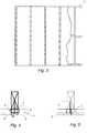
- an expressed joint panelised cladding system according to the invention is shown generally at 1.
- the system 1 includes a plurality of battens 2 securable to an underlying building structure in the form of a frame 3 and a plurality of fibre cement cladding panels 4 having front and rear sealed surfaces 5 and 6 respectively.
- the battens 2 are in a simple strip form and have a frame engaging surface 7 and an integrally formed finish-ready panel supporting surface 8. In use, the exposed portion of this surface 8 forms an external recessed surface of an expressed joint as shown in the drawings.
- the battens 2 are preferably made from a medium to low-density nailable fibre cement which is either sealed on at least the finish-ready surface 8 or has a composition that makes the outer surfaces inherently weather resistant and finish-ready. Desirably the density is in the range 0.8 to 1.3 g/cc and more preferably 0.8-1.2 g/cc.
- the batten material is formulated to meet the requirements of Australian Standard AS/NZS 2908.2:2000 relating to Type A external sheets, or similar.
- the fibre cement batten composition includes density modifiers such as: inorganic hollow or foamed microparticles (see for example WO 01/68547 ); calcium silicate hydrate; entrained air and other suitable density reducing additives, or any combination thereof.
- density modifiers such as: inorganic hollow or foamed microparticles (see for example WO 01/68547 ); calcium silicate hydrate; entrained air and other suitable density reducing additives, or any combination thereof.
- batten illustrated has a flat frame engaging surface 7, this surface and/or the main body of the batten could have ridges or functionally equivalent formations that would allow fluid flow therethrough if required. This is particularly useful where the battens are to be secured horizontally and can also facilitate additional ventilation when mounted in other orientations.
- the preferred battens have a thickness of at least 18-19mm and a width of between 45mm and 70mm. These are ideally constructed from a medium to low density fibre cement that has density modifying additives in the form of spherical inorganic hollow microparticles such as those described in patent application WO 01/68547 .
- the batten minimum thickness ensures sufficient fastener holding power to enable the cladding panels to be secured to the battens without the need to fix through to the underlying building structure.
- This thickness of batten also provides an air gap of sufficient depth to act as an effective insulating barrier to resist heat transfer and increase the overall "R" value rating of the structure.
- the cladding panels 4 are preferably made from a medium density nailable fibre cement, which is at least partially weather resistant on it's front and rear faces. In the preferred form the panels are coated on all six sides using a radiation curable sealer. Ideally, these panels also meet the requirements of AS/NZS 2908.2:2000 or similar standard.
- the fibre cement panel composition includes density modifiers such as: inorganic hollow or foamed microparticles (see for example WO 01/68547 ); calcium silicate hydrate; entrained air and other suitable density reducing additives, or any combination thereof.
- the strip is made from thin gauge metal or polymeric material and has an outwardly protruding ridge 11 along the joint region as shown that spans between the battens forming the backing of an expressed joint in the same plane as the batten surface 8.
- the starting structure before the installation of the expressed joint facade system should be typical of the state ready for conventional cladding installation.
- This preferably includes the installation of a drainage plane 12, which most commonly comprises a pliable building membrane or moisture barrier such as a sarking, building wrap or building paper.
- a drainage plane 12 which most commonly comprises a pliable building membrane or moisture barrier such as a sarking, building wrap or building paper.
- a pliable building membrane or moisture barrier such as a sarking, building wrap or building paper.
- suitable building membranes and underlays for use in Australia is set out in AS/NZS 4200.1:1994.
- rigid barriers could also be used.
- a vent strip 13 is then installed at the bottom of the framing base plate 14 adjacent the concrete slab 15 which may be rebated (as shown) or square, with the edge of the bent strip level or slightly lower than the bottom of the framing as shown in Fig. 6 . This is preferably done prior to the installation of the battens 2.
- the sub-frame is generally framing timber but can be other framing materials such as steel.
- Fastening into timber framing is done with nails, preferably 65 mm galvanised ring-shanked flathead nails.
- Fastening into steel framing may be done with screws, preferably 40 mm long HardiDrive screws or similar self-driving screws with corrosion-resistance.
- any suitable fastener or securing means may be used to secure the battens 2 to the sub-framing.
- the vertical battens 2 are positioned to coincide with vertical joint positions, plus any necessary intermediate support positions.
- the vertical battens are usually positioned on vertical framing members and the layout of vertical joints are designed to coincide where possible, but if no framing member is available then auxiliary framing members can be added to the sub-frames to support the batten.
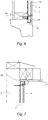
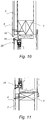
- Battens can also be used to form internal and external expressed corner joints as shown in Figs. 8 and 9 .
- the battens may also be used to form the joint between vertical and horizontal surfaces or junctions to form an expressed joint at the junction, or just to support the horizontal edge.
- Positioning of the battens adjacent eave to wall corners can be straightforward as shown in Figure 7 with a small gap 16 being left above the batten 2 (and cladding panel 4) to allow location of the eave sheet 17 as shown. Ventilation through the framing above the eave sheet can also provide venting to the roof space and via a roof vent to the outside of the building, This passage of air can be provided by framing provisions such as packers, grooves at the back of the eave framing, gaps in the eave framing against the wall framing or drilled holes in the eave framing.
- the wall cavity can be closed at the cladding/eave sheet junction or vented to allow passage of rising hot air to pass to the outside of the building at the eave level.
- the first panel 4 is installed, preferably the bottom corner panel, from which subsequent panels are spaced.
- backing strips 10 are usually pre-connected to the panels, ideally using double sided adhesive tape.
- the panel is usually fixed level and plumb, but can be angled to produce an unusual architectural look if the framing and battens are set up to suit.
- the panels are fixed to the battens with screws or nails.
- Typical nails used are 30 mm ⁇ 2.8 mm diameter galvanized fibre cement nails, but more suitable for ease of installation is the use of corrosion-resistant finishing nails, T-head nails or brad nails that are quickly and easily installed by nail guns which, when the nail gun is set to leave the nail flush with the surface, need no patching prior to painting.
- An example of a suitable gun is the "Paslode Impulse 250 II Bradder”.
- a typical brad nail used is a "Paslode” 25 mm long stainless steel or galvanised “Paslode” C1 or ND brad.
- Typical screws for attaching panels to battens 2 include various panhead, waferhead, countersunk and hexagon head screws, typically 25 mm long and 8 or 10 gauge. The selection of screw will depend on the desired finish and whether the fasteners are intended to be concealed.
- a typical adhesive is James Hardie Joint Sealant (JHJS) or a moisture polyurethane or hot melt adhesive, but other adhesives can also be used.
- JHJS James Hardie Joint Sealant
- the adhesive is applied as a continuous bead and also serves the dual function of sealing the panel top and side edges and optionally also the bottom edge.
- a typical example of a double-sided tape suitable for use to connect backing strips to panels and panels to battens is 3MTM or VHBTM double-sided tape, preferably 0.5 mm to 2 mm thick and 5 mm to 30 mm wide. However, other double-sided tapes can be used.
- fastener and adhesive or fastener and double-sided tape can be used to supplement attachment to either reduce the number of fasteners visible, or that need patching, or to achieve the necessary wind load resistance.
- a sealant is used to seal the panel top and side edges and optionally the bottom edge between the panel edge and the batten or horizontal backing strip.
- first panel is secured, further panels are attached to the battens by maintaining or offsetting the alignment of the first panel and attaching in a similar fashion to the previous panel.
- the gap between the panels is typically 0 to 20 mm, but is preferably about 10 mm to express the joint to be visible when approaching the building and is usually in a predetermined configuration and pattern.
- the means of fixing, adhering and sealing are then repeated as described above. As shown, it is the exposed strip of the integral panel supporting surface of the batten that forms the external recessed surface of the expressed joint.
- patching compounds can be used to fill over the fasteners so that the holes are flush with the surface of the panels.
- the patching material is typically a two-part epoxy such as megapoxy PI or Hilti CA125. Where the temperature is below 15°C, the use of Hilti CA 273 is preferred.
- the holes over the fasteners are filled flat or slightly proud of the surface of the panel. After the patching material is set, sanding of the patching may be necessary in some areas to blend the patch surface to the same surface as the surrounding panel.
- the panels are finished in situ. Typically, this is achieved through applying a minimum of two coats of exterior grade paint.
- the surfaces of the expressed joints are to be coloured the same as the panels, this is usually done as a simple post-installation painting process when painting the panels.
- the open edges of the joint may be pre-finished prior to installation or at least prior to painting the panels.
- the edges of the panels can be painted in the required contrasting colour and the panel mounting surface 8 of the battens 2 similarly pre-painted at least along a generally centrally located region where the defined joint will be positioned.
- batten thickness of the preferred embodiment Another advantage relating to the batten thickness of the preferred embodiment is that conventional domestic market windows can still be used without the need for complex setting, as the overall frame to outer surface distance is comparable to other cladding systems.
- most of the other expressed joint systems using top hat battens and the like require either the use of more expensive commercial windows which accommodate a larger overall cladding depth or extra finishing and setting work if domestic windows are used.
- the preferred thickness of 18-19mm also provides an effective insulating air gap between the building structure and the cladding panels.
- sealing components that are located intermediate the outermost surface of the battens and the rear surfaces of the cladding panel system.
- these sealing components comprise separate metal or polymeric strips with integrally attached gasket-type elements, and in other cases comprise separate strips of compressible sealing material that can be made of any number of suitable materials.
- the battens have an integrally formed finish-ready panel supporting surface which, in use, forms an exposed surface of the expressed joint formed thereon.
- Sealing if required, is achieved either by means of the adhesive, that may optionally be used to secure the panels to the battens and backing strips (where used), or by use of a manually applied spreadable sealant which can be applied after the panels are installed and which in any event are required for use with most of the prior art systems in addition to the other sealing mechanisms provided.
- finishing nails means that there is no pre-drilling of the cladding panels, as has been required in many of the commercial systems, and secondly, high speed nail guns can be used. Most importantly, careful use of finishing nails can obviate the need for any filling or patching prior to painting.
- Another advantage of the preferred form of the present invention is that by using a relatively solid batten having good fastener holding properties, there is no need for the panel to be anchored back to the framing. This also potentially facilitates the use of smaller, less expensive fasteners than some of those used in the prior art.
- the invention also contemplates the use of thin section battens wherever the panels are anchored by fasteners extending through these and into the underlying building structure, with significant advantages still arising from the simplified batten defining the recessed surface of the expressed joint. It should also be appreciated that whilst the preferred embodiment described is a system adapted for securement to a building structure in the form of a building frame most preferably of timber, it can easily be adapted for use with other building structures including those made of masonary and/or concrete.
Landscapes
- Engineering & Computer Science (AREA)
- Architecture (AREA)
- Physics & Mathematics (AREA)
- Electromagnetism (AREA)
- Civil Engineering (AREA)
- Structural Engineering (AREA)
- Finishing Walls (AREA)
Claims (18)
- Paneelverkleidungssystem (1) mit markierten Fugen, umfassend:eine Mehrzahl von nagelbaren Faserzementleisten (2) mit niedriger Dichte, die an einer Gebäudestruktur sicherbar sind, wobei jede nagelbare Faserzementleiste (2) mit niedriger Dichte eine einfache Streifenform aufweist, die eine Flachrahmenstruktureingriffsfläche (7) und eine integral ausgebildete, abschlussfertige Flachplattentragfläche (8) umfasst; undzumindest zwei Faserzementverkleidungsplatten (4), wobei die zumindest zwei Faserzementverkleidungsplatten (4) direkt an oder durch eine(r) oder mehrere(n) der Mehrzahl von nagelbaren Faserzementleisten (2) mit niedriger Dichte sicherbar sind, sodass die zumindest zwei Faserzementverkleidungsplatten (4) an der einen oder den mehreren der Mehrzahl von nagelbaren Faserzementleisten (2) mit niedriger Dichte voneinander beabstandet sind, um einen Spalt zwischen den zumindest zwei Faserzementverkleidungsplatten (4) auszubilden, und wobei die exponierte Fläche der abschlussfertigen Plattentragfläche (8) innerhalb des Spalts der oder jeder nagelbaren Faserzementleiste (2) mit niedriger Dichte eine vertiefte Außenfläche einer markierten Fuge ausbildet.
- Paneelverkleidungssystem mit markierten Fugen nach Anspruch 1, wobei die zumindest zwei Faserzementverkleidungsplatten (4) abgedichtete Vorder- (5) und Rückflächen (6) aufweisen.
- Paneelverkleidungssystem mit markierten Fugen nach einem der vorangehenden Ansprüche, wobei jede nagelbare Faserzementleiste (2) mit niedriger Dichte von ausreichender Dicke ist und ausreichende nagelhaltende Eigenschaften aufweist, sodass, nachdem jede nagelbare Faserzementleiste (2) mit niedriger Dichte anhand geeigneter Befestigungsmittel an der darunterliegenden Gebäudestruktur gesichert worden ist, die zumindest zwei Faserzementverkleidungsplatten (4) allein durch Befestigung an der nagelbaren Faserzementleiste (2) mit niedriger Dichte gehalten werden können.
- Paneelverkleidungssystem mit markierten Fugen nach Anspruch 3, wobei jede nagelbare Faserzementleiste (2) mit niedriger Dichte eine Dicke von 18 bis 19 mm, eine Breite von 45 bis 70 mm und eine Dichte von 0,8 g/cc bis 1,2 g/cc aufweist.
- Paneelverkleidungssystem mit markierten Fugen nach einem der Ansprüche 1 bis 4, wobei die zumindest zwei Faserzementverkleidungsplatten (4) mit Hilfe von Befestigungsmitteln gesichert sind, die sich durch die nagelbaren Faserzementleisten (2) mit niedriger Dichte und in die darunterliegende Gebäudestruktur erstrecken.
- Paneelverkleidungssystem mit markierten Fugen nach einem der vorangehenden Ansprüche, wobei eine oder mehrere der Mehrzahl von nagelbaren Faserzementleisten (2) mit niedriger Dichte vertikal am Gebäuderahmen gesichert sind und wobei eine Mehrzahl von dünnen Unterlegstreifen (10), die jeder einen vorstehenden Mittelsteg (11) aufweisen, bereitgestellt ist, um eine abdichtbare horizontale vertiefte Außenfläche einer markierten Fuge zu schaffen, die sich zwischen den im Allgemeinen vertikalen nagelbaren Faserzementleisten (2) mit niedriger Dichte entlang Kanten der zumindest zwei Faserzementplatten (4), die nicht an einer nagelbaren Faserzementleiste (2) mit niedriger Dichte ausgerichtet sind, erstrecken.
- Paneelverkleidungssystem mit markierten Fugen nach einem der Ansprüche 1 bis 6, wobei eine oder mehrere der Mehrzahl von nagelbaren Faserzementleisten (2) mit niedriger Dichte erforderlichenfalls anhand zusätzlicher Rahmenträger horizontal gesichert sind und wobei ferner nagelbare Faserzementleisten (2) mit niedriger Dichte oder Unterlegstreifen (10) verwendet werden, um erforderlichenfalls zusätzliche Fugenflächen zu definieren.
- Paneelverkleidungssystem mit markierten Fugen nach einem der vorangehenden Ansprüche, wobei die zumindest zwei Faserzementverkleidungsplatten (4) anhand von Kleinkopfnägeln gesichert sind.
- Verwendung einer nagelbaren Faserzementplattentragleiste mit niedriger Dichte in einem Paneelverkleidungssystem mit markierten Fugen nach einem der Ansprüche 1 bis 8, wobei die nagelbare Faserzementplattentragleiste (2) mit niedriger Dichte die Form eines längsverlaufenden nagelbaren Faserzementstreifens mit einer Gebäudestruktureingriffsfläche (7) und einer Plattentragfläche (8) aufweist, wobei die nagelbare Faserzementplattentragleiste (2) mit niedriger Dichte zumindest an ihrer Plattentragfläche (8) abschlussfertig ist.
- Verwendung einer nagelbaren Faserzementplattentragleiste (2) mit niedriger Dichte nach Anspruch 9, wobei die Plattentragfläche (8) mit Hilfe einer geeigneten Oberflächenbeschichtung abschlussfertig gemacht wird.
- Paneelverkleidungswand mit markierten Fugen, einschließlich:
einer Gebäudestruktur, an der ein Paneelverkleidungssystem (1) mit markierten Fugen nach einem der Ansprüche 1 bis 8 gesichert ist. - Verfahren zur Konstruktion einer Paneelverkleidungswand mit markierten Fugen, wobei das Verfahren die folgenden Schritte umfasst:Errichten einer Gebäudestruktur (3);Sichern einer Mehrzahl von nagelbaren Faserzementleisten (2) mit niedriger Dichte an der Gebäudestruktur, wobei jede nagelbare Faserzementleiste mit niedriger Dichte die Form eines einfachen Streifens mit einer Flachstruktureingriffsfläche (7) und einer integral ausgebildeten, abschlussfertigen Flachplattentragfläche (8) aufweist; undSichern von zumindest zwei Faserzementverkleidungsplatten (4) direkt an oder durch eine(r) oder mehrere(n) der Mehrzahl von nagelbaren Faserzementleisten (2) mit niedriger Dichte;wobei die zumindest zwei Faserzementverkleidungsplatten (4) an der einen oder den mehreren der Mehrzahl von nagelbaren Faserzementleisten (2) mit niedriger Dichte voneinander beabstandet sind, um einen Spalt zwischen den zumindest zwei Faserzementverkleidungsplatten (4) auszubilden, sodass die abschlussfertige Plattentragfläche (8) an zumindest einigen der nagelbaren Faserzementleisten (2) mit niedriger Dichte innerhalb des Spalts freiliegt und eine vertiefte Außenfläche einer markierten Fuge ausbildet.
- Verfahren nach Anspruch 12, ferner umfassend den Schritt des Verbindens einer geeigneten Entwässerungsebene, wie etwa einer Gebäudehülle, einer starren Barriere, einer Folie, einer wasserdichten Beschichtung oder einer Unterspannbahn, mit der Gebäudestruktur vor dem Sichern der nagelbaren Faserzementleisten (2) mit niedriger Dichte.
- Verfahren nach einem der Ansprüche 12 oder 13, wobei die Gebäudestruktur einen aus Holz gefertigten Rahmen (3) umfasst.
- Verfahren nach einem der Ansprüche 12 bis 14, wobei die Faserzementverkleidungsplatten nagelbar sind und mit Hilfe von Endbearbeitungsnägeln an den oder durch die darunterliegende(n) nagelbare(n) Faserzementleisten (2) mit niedriger Dichte gesichert sind.
- Verfahren nach einem der Ansprüche 12 bis 15, ferner umfassend den Schritt des Befestigens von Unterlegstreifen entlang der horizontalen Kanten der zumindest zwei Faserzementverkleidungsplatten (4), wobei es keine darunterliegende nagelbare Faserzementleiste (2) mit niedriger Dichte gibt.
- Verfahren nach Anspruch 16, wobei der Unterlegstreifen (10) optional mit der abgedichteten Rückseite der Faserzementverkleidungsplatte (4) vorverbunden ist.
- Verfahren nach einem der Ansprüche 12 bis 17, ferner umfassend den Schritt des Installierens eines an die Basis des Rahmens (3) angrenzenden Lüftungsstreifens (13).
Applications Claiming Priority (2)
| Application Number | Priority Date | Filing Date | Title |
|---|---|---|---|
| AU2006900528A AU2006900528A0 (en) | 2006-02-03 | Expressed joint facade system | |
| PCT/AU2007/000096 WO2007087681A1 (en) | 2006-02-03 | 2007-02-01 | Expressed joint facade system |
Publications (3)
| Publication Number | Publication Date |
|---|---|
| EP1979554A1 EP1979554A1 (de) | 2008-10-15 |
| EP1979554A4 EP1979554A4 (de) | 2014-01-01 |
| EP1979554B1 true EP1979554B1 (de) | 2019-01-23 |
Family
ID=38327086
Family Applications (1)
| Application Number | Title | Priority Date | Filing Date |
|---|---|---|---|
| EP07701429.8A Active EP1979554B1 (de) | 2006-02-03 | 2007-02-01 | Fassadensystem mit markierten fugen |
Country Status (6)
| Country | Link |
|---|---|
| US (1) | US8689509B2 (de) |
| EP (1) | EP1979554B1 (de) |
| AU (2) | AU2007211837B2 (de) |
| CA (1) | CA2641584C (de) |
| NZ (1) | NZ569951A (de) |
| WO (1) | WO2007087681A1 (de) |
Families Citing this family (13)
| Publication number | Priority date | Publication date | Assignee | Title |
|---|---|---|---|---|
| WO2008106735A1 (en) * | 2007-03-08 | 2008-09-12 | James Hardie International Finance B.V. | Building system |
| AU2008229568C1 (en) * | 2007-03-21 | 2013-10-10 | James Hardie Technology Limited | Framed wall construction and method |
| AU320072S (en) | 2008-03-07 | 2008-06-30 | Hardie James Technology Ltd | Building element |
| AU326889S (en) | 2009-05-29 | 2009-07-27 | Hardie James Technology Ltd | Building element |
| AU326890S (en) | 2009-05-29 | 2009-07-27 | Hardie James Technology Ltd | Building element |
| USD659858S1 (en) | 2010-04-08 | 2012-05-15 | Russ Schaefer | Foam board |
| GB2496855A (en) * | 2011-11-22 | 2013-05-29 | Hardie James Technology Ltd | Cladding element for use in wall construction |
| CA2945313A1 (en) * | 2014-04-11 | 2015-10-15 | Ascensia Diabetes Care Holdings Ag | Wireless transmitter adapters for battery-operated biosensor meters and methods of providing same |
| JP2016079757A (ja) * | 2014-10-22 | 2016-05-16 | 奥地建産株式会社 | 下地壁構造体及びその施工方法 |
| WO2017112691A1 (en) * | 2015-12-23 | 2017-06-29 | James Hardie Technoloy Limited | A building system |
| AU2017235485B2 (en) * | 2016-03-17 | 2022-02-17 | James Hardie Technology Limited | A fastening system |
| US11007697B1 (en) | 2017-10-25 | 2021-05-18 | Green Bay Decking, LLC | Composite extruded products and systems for manufacturing the same |
| US10792512B1 (en) * | 2019-03-29 | 2020-10-06 | Pedro Kahn Machado DE SOUZA | Metallic modules and assembly system for the formation of shielded walls, floor and ceiling for rooms used for radiotherapy |
Family Cites Families (86)
| Publication number | Priority date | Publication date | Assignee | Title |
|---|---|---|---|---|
| US1630801A (en) * | 1926-07-31 | 1927-05-31 | Floyd Y Parsons | Wall construction |
| US1698557A (en) * | 1927-04-28 | 1929-01-08 | Denis J O'brien | Concrete structure |
| GB558239A (en) | 1942-08-07 | 1943-12-28 | Leslie Shingleton | Improvements relating to concrete structures |
| GB564447A (en) | 1943-03-26 | 1944-09-28 | Leslie Shingleton | Improvements in and relating to the moulding of concrete structures |
| BE657693A (de) | 1964-01-04 | |||
| GB1174902A (en) | 1966-05-03 | 1969-12-17 | Alan William David Marshall | Improvements in and relating to Building Structures |
| GB1206395A (en) * | 1966-10-25 | 1970-09-23 | Colin Henry Davidson | Improvements relating to cast or moulded building units |
| US3613326A (en) | 1969-10-03 | 1971-10-19 | Alside Int Corp | Preformed simulated brick panel having stepped edges |
| US3869295A (en) * | 1970-03-30 | 1975-03-04 | Andrew D Bowles | Uniform lightweight concrete and plaster |
| US4076884A (en) * | 1972-03-22 | 1978-02-28 | The Governing Council Of The University Of Toronto | Fibre reinforcing composites |
| US3986312A (en) * | 1973-10-05 | 1976-10-19 | Ralph Calhoun | Demountable wall assembly and components therefor |
| DE2440497A1 (de) | 1974-08-23 | 1976-03-11 | Polyplast Gmbh | Verkleidungselement |
| US4052829A (en) * | 1976-03-17 | 1977-10-11 | Chapman Ward W | Semi-prefabricated monolithic steel-reinforced cement building construction |
| US4068434A (en) * | 1976-04-05 | 1978-01-17 | Day Stephen W | Composite wall panel assembly and method of production |
| US4074141A (en) * | 1976-04-23 | 1978-02-14 | Bryant Frank E | Prefabricated X-radiation protection panels |
| SE403640B (sv) * | 1976-06-24 | 1978-08-28 | Thoren Torgny | Byggelement |
| US4275534A (en) * | 1977-06-13 | 1981-06-30 | W. H. Porter, Inc. | Hexagonal building structures |
| GB1590875A (en) | 1977-09-23 | 1981-06-10 | Linton D | Cladding panelling for building structures |
| US4194336A (en) * | 1977-11-21 | 1980-03-25 | Weinar Roger N | Concealable retaining clip for wallboards |
| GB2012331B (en) * | 1978-01-10 | 1982-04-28 | Sweet B A | Building system |
| DK63179A (da) * | 1979-02-14 | 1980-08-15 | Rockwool Int | Fiberarmeret cementprodukt samt fremgangsmaade til fremstilling af samme |
| EP0024360A1 (de) | 1979-08-16 | 1981-03-04 | Rütgerswerke Aktiengesellschaft | Verkleidungselement für Fassadenflächen |
| US4366657A (en) * | 1980-03-05 | 1983-01-04 | Fred Hopman | Method and form for mechanically pouring adobe structures |
| FI69178C (fi) | 1980-03-28 | 1985-12-10 | Heikki Saetilae | Byggnadssystem baserat pao tunna betongplattor och kassettelement foer genomfoerande av detsamma |
| WO1983000895A1 (fr) | 1981-09-09 | 1983-03-17 | Reinle, Erwin | Element de revetement en forme de plaque |
| US4516373A (en) * | 1981-10-26 | 1985-05-14 | Yoshinori Osawa | Apparatus for tile-setting |
| SE453181B (sv) * | 1983-10-05 | 1988-01-18 | Bengt Hedberg | Sett att framstella lettballastbetong |
| US4651484A (en) * | 1986-03-31 | 1987-03-24 | National Gypsum Company | Furniture channel |
| US4680911A (en) * | 1986-05-21 | 1987-07-21 | Davis Richard A | Decorative wall covering |
| IL83208A (en) * | 1987-07-16 | 1993-01-14 | Tafi Trade & Finance | Building structure having high blast and penetration resistance |
| NZ221573A (en) | 1987-08-26 | 1991-02-26 | New Zealand Forest Prod | Fibre reinforced cement composites and their preparation |
| US4854095A (en) * | 1987-10-29 | 1989-08-08 | The Standard Products Company | Color cap system for locking strip gaskets |
| CA1341084C (en) | 1987-11-16 | 2000-08-15 | George W. Green | Coated fibrous mat-faced gypsum board resistant to water and humidity |
| US4963430A (en) * | 1989-01-06 | 1990-10-16 | Illinois Tool Works Inc. | Corrosion and split resistant plastic materials |
| US5242736A (en) * | 1989-01-06 | 1993-09-07 | Illinois Tool Works Inc. | Seamless tube useful to make roofing battens and related method |
| GB8926808D0 (en) | 1989-11-28 | 1990-01-17 | Coseley Building Systems Ltd | A cladding panel and system |
| US5473849A (en) | 1992-05-28 | 1995-12-12 | Materials Technology, Limited | Building wall and method of constructing same |
| US5417020A (en) * | 1992-08-12 | 1995-05-23 | Dobija; Michael J. | Wall system providing an array of individual panels |
| JPH06278116A (ja) | 1993-03-26 | 1994-10-04 | Kubota Corp | コンクリート工事用永久型枠 |
| US5724783A (en) * | 1993-12-27 | 1998-03-10 | Mandish; Theodore O. | Building panel apparatus and method |
| JPH084248A (ja) | 1994-06-20 | 1996-01-09 | Chiyuuo:Kk | サイディングの目地ジョイナー |
| JPH0868184A (ja) | 1994-08-30 | 1996-03-12 | Ask:Kk | 建築用パネル |
| US5622556A (en) * | 1994-12-19 | 1997-04-22 | Shulman; David M. | Lightweight, low water content cementitious compositions and methods of their production and use |
| US5974748A (en) * | 1995-02-09 | 1999-11-02 | Fit-Z-All Corner Plugs | Corner insert for vinyl siding |
| AUPN504095A0 (en) * | 1995-08-25 | 1995-09-21 | James Hardie Research Pty Limited | Cement formulation |
| US6148573A (en) * | 1995-10-17 | 2000-11-21 | Drywall Systems International Inc | Non coatable drywall finishing system |
| US5736594A (en) * | 1996-03-28 | 1998-04-07 | B J Services Company | Cementing compositions and methods using recycled expanded polystyrene |
| AUPO215996A0 (en) | 1996-09-05 | 1996-10-03 | James Hardie International Finance B.V. | An improved cladding board mounting system |
| NZ502017A (en) | 1996-09-05 | 2001-01-26 | James Hardie Res Pty Ltd | Cladding board mounting system includes resilient mounting means |
| AUPO291296A0 (en) | 1996-10-11 | 1996-11-07 | Rudduck, Dickory | Building elements |
| AUPO303296A0 (en) * | 1996-10-16 | 1996-11-14 | James Hardie International Finance B.V. | Wall member and method of construction thereof |
| US5732520A (en) * | 1996-12-10 | 1998-03-31 | Multicoat Corporation | Synthetic stucco system |
| JP3289642B2 (ja) | 1997-04-04 | 2002-06-10 | 株式会社イナックス | サイディング端部の納まり構造 |
| US6122877A (en) * | 1997-05-30 | 2000-09-26 | Andersen Corporation | Fiber-polymeric composite siding unit and method of manufacture |
| US5960598A (en) * | 1997-07-25 | 1999-10-05 | Tamlyn; John Thomas | Building construction inside corner excluding water entry |
| US6018924A (en) * | 1997-08-21 | 2000-02-01 | Tamlyn; John Thomas | Adjustable reveal strip and related method of construction |
| JPH11256683A (ja) | 1998-03-12 | 1999-09-21 | Maeda Corp | 繊維補強モルタルパネル、長耐久性住宅構法、壁構法および野地板用パネル |
| US6170214B1 (en) | 1998-06-09 | 2001-01-09 | Kenneth Treister | Cladding system |
| JP2000064554A (ja) | 1998-08-20 | 2000-02-29 | Matsushita Electric Works Ltd | 壁パネル |
| US6155014A (en) * | 1999-03-17 | 2000-12-05 | Unistrut Insternational Corporation | Clean room wall system |
| DE19922086A1 (de) * | 1999-05-17 | 2000-11-23 | Hilti Ag | Säge zum Schneiden von harten Materialien |
| ATE368017T1 (de) | 2000-03-14 | 2007-08-15 | James Hardie Int Finance Bv | Faserzementbaumaterialien mit zusatzstoffen niedriger dichte |
| US6295776B1 (en) * | 2000-05-17 | 2001-10-02 | Phillips Manufacturing Co. | Corner bead drywall trim and method of manufacture |
| US6341458B1 (en) * | 2000-06-08 | 2002-01-29 | Crane Products Ltd. | Extruded composite corners for building construction |
| EP1328689A4 (de) | 2000-09-27 | 2005-10-05 | Hiltive Pty Ltd | Bauplatte, anordnung und verfahren |
| AU2003204739B2 (en) | 2000-09-27 | 2005-01-20 | Hiltive Pty Limited | Building panel, assembly and method |
| US6516580B1 (en) * | 2000-11-13 | 2003-02-11 | Multicoat Corporation | Synthetic stucco system with moisture absorption control |
| JP2002161623A (ja) | 2000-11-27 | 2002-06-04 | Mitsui Home Co Ltd | 外装下地構造及び外装下地工法 |
| GB2374893B (en) * | 2001-04-25 | 2004-08-04 | Framegard Anchoring Systems Lt | An anchoring profile, a frame assembly and a method for securing a pane against impact |
| US6571523B2 (en) * | 2001-05-16 | 2003-06-03 | Brian Wayne Chambers | Wall framing system |
| WO2002096824A1 (en) | 2001-05-29 | 2002-12-05 | Gojo, Naamloze Vennootschap | Wall element, as well as covering for walls, wall elements and the like |
| GB2378192A (en) | 2001-08-01 | 2003-02-05 | Comfyfloor Systems Ltd | Wall cladding system with interlocking base members |
| US6758017B2 (en) * | 2001-08-27 | 2004-07-06 | Peter P. Young | Drywall inside corner device |
| AUPR843201A0 (en) | 2001-10-23 | 2001-11-15 | James Hardie Research Pty Limited | Wall construction method |
| AU2003901529A0 (en) | 2003-03-31 | 2003-05-01 | James Hardie International Finance B.V. | A durable high performance fibre cement product and method of making the same |
| US7028436B2 (en) * | 2002-11-05 | 2006-04-18 | Certainteed Corporation | Cementitious exterior sheathing product with rigid support member |
| AU2003257906A1 (en) | 2002-12-20 | 2004-07-08 | Carter Holt Harvey Limited | Cladding Assemblies and Methods (Flash/Clad TM Procedures) |
| AU2003903440A0 (en) | 2003-07-04 | 2003-07-17 | James Hardie International Finance B.V. | Rainscreen apparatus and method |
| EP1676010A4 (de) | 2003-10-13 | 2008-10-08 | Soo-Chang Moon | Dauerhaft angeordnetes, isoliertes formsystem aus faserverstärkter zementplatte und schaumkunststoff mit perforiertem metallbolzen für betonverstärkte konstruktion |
| WO2005068741A1 (en) | 2004-01-20 | 2005-07-28 | Jetstone Building Systems Pty Ltd | Composite constructional element and method of manufacturing a composite constructional element |
| NZ549746A (en) | 2004-02-11 | 2009-03-31 | Hiltive Pty Ltd | Building assembly component consisting of an elongate cladding support member with a H shaped cross section |
| NZ549407A (en) * | 2004-02-27 | 2009-04-30 | James Hardie Int Finance Bv | Batten mounting water management system |
| NZ536129A (en) | 2004-10-26 | 2006-02-24 | Graeme Bruce Webster | Ventilating building sheet batten |
| JP2007016428A (ja) | 2005-07-06 | 2007-01-25 | Matsushita Electric Works Ltd | サイディング端部用部材 |
| WO2008106735A1 (en) * | 2007-03-08 | 2008-09-12 | James Hardie International Finance B.V. | Building system |
| US7784222B2 (en) * | 2007-09-12 | 2010-08-31 | Flashing By Design, Inc. | Siding system and method |
-
2007
- 2007-02-01 US US12/278,085 patent/US8689509B2/en active Active
- 2007-02-01 CA CA2641584A patent/CA2641584C/en active Active
- 2007-02-01 WO PCT/AU2007/000096 patent/WO2007087681A1/en not_active Ceased
- 2007-02-01 EP EP07701429.8A patent/EP1979554B1/de active Active
- 2007-02-01 NZ NZ569951A patent/NZ569951A/en unknown
- 2007-02-01 AU AU2007211837A patent/AU2007211837B2/en active Active
-
2010
- 2010-05-28 AU AU2010100532A patent/AU2010100532B4/en not_active Expired
Non-Patent Citations (1)
| Title |
|---|
| None * |
Also Published As
| Publication number | Publication date |
|---|---|
| AU2010100532A4 (en) | 2010-06-24 |
| NZ569951A (en) | 2010-04-30 |
| EP1979554A4 (de) | 2014-01-01 |
| AU2007211837B2 (en) | 2011-03-03 |
| US8689509B2 (en) | 2014-04-08 |
| AU2007211837A1 (en) | 2007-08-09 |
| CA2641584C (en) | 2013-07-09 |
| EP1979554A1 (de) | 2008-10-15 |
| US20090019814A1 (en) | 2009-01-22 |
| AU2010100532B4 (en) | 2010-07-08 |
| WO2007087681A1 (en) | 2007-08-09 |
| CA2641584A1 (en) | 2007-08-09 |
Similar Documents
| Publication | Publication Date | Title |
|---|---|---|
| EP1979554B1 (de) | Fassadensystem mit markierten fugen | |
| US20080104918A1 (en) | Cavity Wall System | |
| US9512665B2 (en) | Universal fenestration cap system and method | |
| US7526897B2 (en) | J-channel backer material | |
| US11306485B2 (en) | Modular building construction system and method | |
| US20050235598A1 (en) | Wall construction method | |
| US20210025176A1 (en) | Resizable Insulated and Watertightness Wall Panel Joint Structure | |
| AU2002332966B2 (en) | Wall construction method | |
| US8516759B2 (en) | System for concealed fastening of building finishing elements | |
| AU2011202644A1 (en) | Expressed joint facade system | |
| WO1999032750A1 (en) | Window or door frame | |
| WO2008003975A1 (en) | A cladding system | |
| AU736849B2 (en) | Window or door frame | |
| AU2016202833B2 (en) | Wall cladding system | |
| WO2008124527A1 (en) | Lap siding systems | |
| AU2005294063A1 (en) | Cavity wall system | |
| NZ719694B2 (en) | Wall cladding system | |
| JPH04176953A (ja) | 家屋 |
Legal Events
| Date | Code | Title | Description |
|---|---|---|---|
| PUAI | Public reference made under article 153(3) epc to a published international application that has entered the european phase |
Free format text: ORIGINAL CODE: 0009012 |
|
| 17P | Request for examination filed |
Effective date: 20080801 |
|
| AK | Designated contracting states |
Kind code of ref document: A1 Designated state(s): AT BE BG CH CY CZ DE DK EE ES FI FR GB GR HU IE IS IT LI LT LU LV MC NL PL PT RO SE SI SK TR |
|
| RAP1 | Party data changed (applicant data changed or rights of an application transferred) |
Owner name: JAMES HARDIE TECHNOLOGY LIMITED |
|
| DAX | Request for extension of the european patent (deleted) | ||
| A4 | Supplementary search report drawn up and despatched |
Effective date: 20131203 |
|
| RIC1 | Information provided on ipc code assigned before grant |
Ipc: F16B 5/00 20060101ALI20131127BHEP Ipc: E04G 23/02 20060101ALI20131127BHEP Ipc: E04D 3/36 20060101ALI20131127BHEP Ipc: E04F 13/07 20060101ALI20131127BHEP Ipc: E04D 3/361 20060101ALI20131127BHEP Ipc: E04B 2/70 20060101ALI20131127BHEP Ipc: E04B 1/61 20060101AFI20131127BHEP Ipc: E04B 2/96 20060101ALI20131127BHEP |
|
| 17Q | First examination report despatched |
Effective date: 20160304 |
|
| STAA | Information on the status of an ep patent application or granted ep patent |
Free format text: STATUS: EXAMINATION IS IN PROGRESS |
|
| GRAP | Despatch of communication of intention to grant a patent |
Free format text: ORIGINAL CODE: EPIDOSNIGR1 |
|
| STAA | Information on the status of an ep patent application or granted ep patent |
Free format text: STATUS: GRANT OF PATENT IS INTENDED |
|
| INTG | Intention to grant announced |
Effective date: 20180828 |
|
| GRAS | Grant fee paid |
Free format text: ORIGINAL CODE: EPIDOSNIGR3 |
|
| GRAA | (expected) grant |
Free format text: ORIGINAL CODE: 0009210 |
|
| STAA | Information on the status of an ep patent application or granted ep patent |
Free format text: STATUS: THE PATENT HAS BEEN GRANTED |
|
| AK | Designated contracting states |
Kind code of ref document: B1 Designated state(s): AT BE BG CH CY CZ DE DK EE ES FI FR GB GR HU IE IS IT LI LT LU LV MC NL PL PT RO SE SI SK TR |
|
| REG | Reference to a national code |
Ref country code: GB Ref legal event code: FG4D |
|
| REG | Reference to a national code |
Ref country code: CH Ref legal event code: EP |
|
| REG | Reference to a national code |
Ref country code: DE Ref legal event code: R096 Ref document number: 602007057484 Country of ref document: DE |
|
| REG | Reference to a national code |
Ref country code: AT Ref legal event code: REF Ref document number: 1091559 Country of ref document: AT Kind code of ref document: T Effective date: 20190215 |
|
| REG | Reference to a national code |
Ref country code: IE Ref legal event code: FG4D |
|
| REG | Reference to a national code |
Ref country code: NL Ref legal event code: MP Effective date: 20190123 |
|
| PG25 | Lapsed in a contracting state [announced via postgrant information from national office to epo] |
Ref country code: NL Free format text: LAPSE BECAUSE OF FAILURE TO SUBMIT A TRANSLATION OF THE DESCRIPTION OR TO PAY THE FEE WITHIN THE PRESCRIBED TIME-LIMIT Effective date: 20190123 |
|
| PG25 | Lapsed in a contracting state [announced via postgrant information from national office to epo] |
Ref country code: ES Free format text: LAPSE BECAUSE OF FAILURE TO SUBMIT A TRANSLATION OF THE DESCRIPTION OR TO PAY THE FEE WITHIN THE PRESCRIBED TIME-LIMIT Effective date: 20190123 Ref country code: PT Free format text: LAPSE BECAUSE OF FAILURE TO SUBMIT A TRANSLATION OF THE DESCRIPTION OR TO PAY THE FEE WITHIN THE PRESCRIBED TIME-LIMIT Effective date: 20190523 Ref country code: SE Free format text: LAPSE BECAUSE OF FAILURE TO SUBMIT A TRANSLATION OF THE DESCRIPTION OR TO PAY THE FEE WITHIN THE PRESCRIBED TIME-LIMIT Effective date: 20190123 Ref country code: FI Free format text: LAPSE BECAUSE OF FAILURE TO SUBMIT A TRANSLATION OF THE DESCRIPTION OR TO PAY THE FEE WITHIN THE PRESCRIBED TIME-LIMIT Effective date: 20190123 Ref country code: PL Free format text: LAPSE BECAUSE OF FAILURE TO SUBMIT A TRANSLATION OF THE DESCRIPTION OR TO PAY THE FEE WITHIN THE PRESCRIBED TIME-LIMIT Effective date: 20190123 Ref country code: LT Free format text: LAPSE BECAUSE OF FAILURE TO SUBMIT A TRANSLATION OF THE DESCRIPTION OR TO PAY THE FEE WITHIN THE PRESCRIBED TIME-LIMIT Effective date: 20190123 |
|
| REG | Reference to a national code |
Ref country code: AT Ref legal event code: MK05 Ref document number: 1091559 Country of ref document: AT Kind code of ref document: T Effective date: 20190123 |
|
| PG25 | Lapsed in a contracting state [announced via postgrant information from national office to epo] |
Ref country code: GR Free format text: LAPSE BECAUSE OF FAILURE TO SUBMIT A TRANSLATION OF THE DESCRIPTION OR TO PAY THE FEE WITHIN THE PRESCRIBED TIME-LIMIT Effective date: 20190424 Ref country code: IS Free format text: LAPSE BECAUSE OF FAILURE TO SUBMIT A TRANSLATION OF THE DESCRIPTION OR TO PAY THE FEE WITHIN THE PRESCRIBED TIME-LIMIT Effective date: 20190523 Ref country code: LV Free format text: LAPSE BECAUSE OF FAILURE TO SUBMIT A TRANSLATION OF THE DESCRIPTION OR TO PAY THE FEE WITHIN THE PRESCRIBED TIME-LIMIT Effective date: 20190123 Ref country code: BG Free format text: LAPSE BECAUSE OF FAILURE TO SUBMIT A TRANSLATION OF THE DESCRIPTION OR TO PAY THE FEE WITHIN THE PRESCRIBED TIME-LIMIT Effective date: 20190423 |
|
| REG | Reference to a national code |
Ref country code: CH Ref legal event code: PL |
|
| REG | Reference to a national code |
Ref country code: DE Ref legal event code: R097 Ref document number: 602007057484 Country of ref document: DE |
|
| PG25 | Lapsed in a contracting state [announced via postgrant information from national office to epo] |
Ref country code: RO Free format text: LAPSE BECAUSE OF FAILURE TO SUBMIT A TRANSLATION OF THE DESCRIPTION OR TO PAY THE FEE WITHIN THE PRESCRIBED TIME-LIMIT Effective date: 20190123 Ref country code: IT Free format text: LAPSE BECAUSE OF FAILURE TO SUBMIT A TRANSLATION OF THE DESCRIPTION OR TO PAY THE FEE WITHIN THE PRESCRIBED TIME-LIMIT Effective date: 20190123 Ref country code: CZ Free format text: LAPSE BECAUSE OF FAILURE TO SUBMIT A TRANSLATION OF THE DESCRIPTION OR TO PAY THE FEE WITHIN THE PRESCRIBED TIME-LIMIT Effective date: 20190123 Ref country code: EE Free format text: LAPSE BECAUSE OF FAILURE TO SUBMIT A TRANSLATION OF THE DESCRIPTION OR TO PAY THE FEE WITHIN THE PRESCRIBED TIME-LIMIT Effective date: 20190123 Ref country code: DK Free format text: LAPSE BECAUSE OF FAILURE TO SUBMIT A TRANSLATION OF THE DESCRIPTION OR TO PAY THE FEE WITHIN THE PRESCRIBED TIME-LIMIT Effective date: 20190123 Ref country code: LU Free format text: LAPSE BECAUSE OF NON-PAYMENT OF DUE FEES Effective date: 20190201 Ref country code: SK Free format text: LAPSE BECAUSE OF FAILURE TO SUBMIT A TRANSLATION OF THE DESCRIPTION OR TO PAY THE FEE WITHIN THE PRESCRIBED TIME-LIMIT Effective date: 20190123 Ref country code: MC Free format text: LAPSE BECAUSE OF FAILURE TO SUBMIT A TRANSLATION OF THE DESCRIPTION OR TO PAY THE FEE WITHIN THE PRESCRIBED TIME-LIMIT Effective date: 20190123 |
|
| REG | Reference to a national code |
Ref country code: BE Ref legal event code: MM Effective date: 20190228 |
|
| REG | Reference to a national code |
Ref country code: IE Ref legal event code: MM4A |
|
| PLBE | No opposition filed within time limit |
Free format text: ORIGINAL CODE: 0009261 |
|
| STAA | Information on the status of an ep patent application or granted ep patent |
Free format text: STATUS: NO OPPOSITION FILED WITHIN TIME LIMIT |
|
| PG25 | Lapsed in a contracting state [announced via postgrant information from national office to epo] |
Ref country code: LI Free format text: LAPSE BECAUSE OF NON-PAYMENT OF DUE FEES Effective date: 20190228 Ref country code: AT Free format text: LAPSE BECAUSE OF FAILURE TO SUBMIT A TRANSLATION OF THE DESCRIPTION OR TO PAY THE FEE WITHIN THE PRESCRIBED TIME-LIMIT Effective date: 20190123 Ref country code: CH Free format text: LAPSE BECAUSE OF NON-PAYMENT OF DUE FEES Effective date: 20190228 |
|
| 26N | No opposition filed |
Effective date: 20191024 |
|
| PG25 | Lapsed in a contracting state [announced via postgrant information from national office to epo] |
Ref country code: IE Free format text: LAPSE BECAUSE OF NON-PAYMENT OF DUE FEES Effective date: 20190201 |
|
| PG25 | Lapsed in a contracting state [announced via postgrant information from national office to epo] |
Ref country code: SI Free format text: LAPSE BECAUSE OF FAILURE TO SUBMIT A TRANSLATION OF THE DESCRIPTION OR TO PAY THE FEE WITHIN THE PRESCRIBED TIME-LIMIT Effective date: 20190123 Ref country code: BE Free format text: LAPSE BECAUSE OF NON-PAYMENT OF DUE FEES Effective date: 20190228 |
|
| PG25 | Lapsed in a contracting state [announced via postgrant information from national office to epo] |
Ref country code: TR Free format text: LAPSE BECAUSE OF FAILURE TO SUBMIT A TRANSLATION OF THE DESCRIPTION OR TO PAY THE FEE WITHIN THE PRESCRIBED TIME-LIMIT Effective date: 20190123 |
|
| PG25 | Lapsed in a contracting state [announced via postgrant information from national office to epo] |
Ref country code: CY Free format text: LAPSE BECAUSE OF FAILURE TO SUBMIT A TRANSLATION OF THE DESCRIPTION OR TO PAY THE FEE WITHIN THE PRESCRIBED TIME-LIMIT Effective date: 20190123 |
|
| PG25 | Lapsed in a contracting state [announced via postgrant information from national office to epo] |
Ref country code: HU Free format text: LAPSE BECAUSE OF FAILURE TO SUBMIT A TRANSLATION OF THE DESCRIPTION OR TO PAY THE FEE WITHIN THE PRESCRIBED TIME-LIMIT; INVALID AB INITIO Effective date: 20070201 |
|
| P01 | Opt-out of the competence of the unified patent court (upc) registered |
Effective date: 20230427 |
|
| REG | Reference to a national code |
Ref country code: DE Ref legal event code: R081 Ref document number: 602007057484 Country of ref document: DE Owner name: JAMES HARDIE TECHNOLOGY, LTD.,, IE Free format text: FORMER OWNER: JAMES HARDIE TECHNOLOGY LIMITED, DUBLIN, IE |
|
| PGFP | Annual fee paid to national office [announced via postgrant information from national office to epo] |
Ref country code: FR Payment date: 20231212 Year of fee payment: 18 |
|
| PGFP | Annual fee paid to national office [announced via postgrant information from national office to epo] |
Ref country code: DE Payment date: 20231205 Year of fee payment: 18 |
|
| REG | Reference to a national code |
Ref country code: DE Ref legal event code: R119 Ref document number: 602007057484 Country of ref document: DE |
|
| PG25 | Lapsed in a contracting state [announced via postgrant information from national office to epo] |
Ref country code: DE Free format text: LAPSE BECAUSE OF NON-PAYMENT OF DUE FEES Effective date: 20250902 |
|
| PGFP | Annual fee paid to national office [announced via postgrant information from national office to epo] |
Ref country code: GB Payment date: 20251211 Year of fee payment: 20 |
|
| PG25 | Lapsed in a contracting state [announced via postgrant information from national office to epo] |
Ref country code: FR Free format text: LAPSE BECAUSE OF NON-PAYMENT OF DUE FEES Effective date: 20250228 |