EP1977141B1 - Wandler mit zwangs-ölführung - Google Patents
Wandler mit zwangs-ölführung Download PDFInfo
- Publication number
- EP1977141B1 EP1977141B1 EP06846948A EP06846948A EP1977141B1 EP 1977141 B1 EP1977141 B1 EP 1977141B1 EP 06846948 A EP06846948 A EP 06846948A EP 06846948 A EP06846948 A EP 06846948A EP 1977141 B1 EP1977141 B1 EP 1977141B1
- Authority
- EP
- European Patent Office
- Prior art keywords
- converter according
- oil
- piston
- chamber
- sealing element
- Prior art date
- Legal status (The legal status is an assumption and is not a legal conclusion. Google has not performed a legal analysis and makes no representation as to the accuracy of the status listed.)
- Ceased
Links
Images




Classifications
-
- F—MECHANICAL ENGINEERING; LIGHTING; HEATING; WEAPONS; BLASTING
- F16—ENGINEERING ELEMENTS AND UNITS; GENERAL MEASURES FOR PRODUCING AND MAINTAINING EFFECTIVE FUNCTIONING OF MACHINES OR INSTALLATIONS; THERMAL INSULATION IN GENERAL
- F16H—GEARING
- F16H45/00—Combinations of fluid gearings for conveying rotary motion with couplings or clutches
- F16H45/02—Combinations of fluid gearings for conveying rotary motion with couplings or clutches with mechanical clutches for bridging a fluid gearing of the hydrokinetic type
-
- F—MECHANICAL ENGINEERING; LIGHTING; HEATING; WEAPONS; BLASTING
- F16—ENGINEERING ELEMENTS AND UNITS; GENERAL MEASURES FOR PRODUCING AND MAINTAINING EFFECTIVE FUNCTIONING OF MACHINES OR INSTALLATIONS; THERMAL INSULATION IN GENERAL
- F16H—GEARING
- F16H45/00—Combinations of fluid gearings for conveying rotary motion with couplings or clutches
- F16H2045/007—Combinations of fluid gearings for conveying rotary motion with couplings or clutches comprising a damper between turbine of the fluid gearing and the mechanical gearing unit
-
- F—MECHANICAL ENGINEERING; LIGHTING; HEATING; WEAPONS; BLASTING
- F16—ENGINEERING ELEMENTS AND UNITS; GENERAL MEASURES FOR PRODUCING AND MAINTAINING EFFECTIVE FUNCTIONING OF MACHINES OR INSTALLATIONS; THERMAL INSULATION IN GENERAL
- F16H—GEARING
- F16H45/00—Combinations of fluid gearings for conveying rotary motion with couplings or clutches
- F16H45/02—Combinations of fluid gearings for conveying rotary motion with couplings or clutches with mechanical clutches for bridging a fluid gearing of the hydrokinetic type
- F16H2045/021—Combinations of fluid gearings for conveying rotary motion with couplings or clutches with mechanical clutches for bridging a fluid gearing of the hydrokinetic type three chamber system, i.e. comprising a separated, closed chamber specially adapted for actuating a lock-up clutch
-
- F—MECHANICAL ENGINEERING; LIGHTING; HEATING; WEAPONS; BLASTING
- F16—ENGINEERING ELEMENTS AND UNITS; GENERAL MEASURES FOR PRODUCING AND MAINTAINING EFFECTIVE FUNCTIONING OF MACHINES OR INSTALLATIONS; THERMAL INSULATION IN GENERAL
- F16H—GEARING
- F16H45/00—Combinations of fluid gearings for conveying rotary motion with couplings or clutches
- F16H45/02—Combinations of fluid gearings for conveying rotary motion with couplings or clutches with mechanical clutches for bridging a fluid gearing of the hydrokinetic type
- F16H2045/0215—Details of oil circulation
-
- F—MECHANICAL ENGINEERING; LIGHTING; HEATING; WEAPONS; BLASTING
- F16—ENGINEERING ELEMENTS AND UNITS; GENERAL MEASURES FOR PRODUCING AND MAINTAINING EFFECTIVE FUNCTIONING OF MACHINES OR INSTALLATIONS; THERMAL INSULATION IN GENERAL
- F16H—GEARING
- F16H45/00—Combinations of fluid gearings for conveying rotary motion with couplings or clutches
- F16H45/02—Combinations of fluid gearings for conveying rotary motion with couplings or clutches with mechanical clutches for bridging a fluid gearing of the hydrokinetic type
- F16H2045/0221—Combinations of fluid gearings for conveying rotary motion with couplings or clutches with mechanical clutches for bridging a fluid gearing of the hydrokinetic type with damping means
- F16H2045/0226—Combinations of fluid gearings for conveying rotary motion with couplings or clutches with mechanical clutches for bridging a fluid gearing of the hydrokinetic type with damping means comprising two or more vibration dampers
-
- F—MECHANICAL ENGINEERING; LIGHTING; HEATING; WEAPONS; BLASTING
- F16—ENGINEERING ELEMENTS AND UNITS; GENERAL MEASURES FOR PRODUCING AND MAINTAINING EFFECTIVE FUNCTIONING OF MACHINES OR INSTALLATIONS; THERMAL INSULATION IN GENERAL
- F16H—GEARING
- F16H45/00—Combinations of fluid gearings for conveying rotary motion with couplings or clutches
- F16H45/02—Combinations of fluid gearings for conveying rotary motion with couplings or clutches with mechanical clutches for bridging a fluid gearing of the hydrokinetic type
- F16H2045/0221—Combinations of fluid gearings for conveying rotary motion with couplings or clutches with mechanical clutches for bridging a fluid gearing of the hydrokinetic type with damping means
- F16H2045/0226—Combinations of fluid gearings for conveying rotary motion with couplings or clutches with mechanical clutches for bridging a fluid gearing of the hydrokinetic type with damping means comprising two or more vibration dampers
- F16H2045/0231—Combinations of fluid gearings for conveying rotary motion with couplings or clutches with mechanical clutches for bridging a fluid gearing of the hydrokinetic type with damping means comprising two or more vibration dampers arranged in series
-
- F—MECHANICAL ENGINEERING; LIGHTING; HEATING; WEAPONS; BLASTING
- F16—ENGINEERING ELEMENTS AND UNITS; GENERAL MEASURES FOR PRODUCING AND MAINTAINING EFFECTIVE FUNCTIONING OF MACHINES OR INSTALLATIONS; THERMAL INSULATION IN GENERAL
- F16H—GEARING
- F16H45/00—Combinations of fluid gearings for conveying rotary motion with couplings or clutches
- F16H45/02—Combinations of fluid gearings for conveying rotary motion with couplings or clutches with mechanical clutches for bridging a fluid gearing of the hydrokinetic type
- F16H2045/0221—Combinations of fluid gearings for conveying rotary motion with couplings or clutches with mechanical clutches for bridging a fluid gearing of the hydrokinetic type with damping means
- F16H2045/0247—Combinations of fluid gearings for conveying rotary motion with couplings or clutches with mechanical clutches for bridging a fluid gearing of the hydrokinetic type with damping means having a turbine with hydrodynamic damping means
-
- F—MECHANICAL ENGINEERING; LIGHTING; HEATING; WEAPONS; BLASTING
- F16—ENGINEERING ELEMENTS AND UNITS; GENERAL MEASURES FOR PRODUCING AND MAINTAINING EFFECTIVE FUNCTIONING OF MACHINES OR INSTALLATIONS; THERMAL INSULATION IN GENERAL
- F16H—GEARING
- F16H45/00—Combinations of fluid gearings for conveying rotary motion with couplings or clutches
- F16H45/02—Combinations of fluid gearings for conveying rotary motion with couplings or clutches with mechanical clutches for bridging a fluid gearing of the hydrokinetic type
- F16H2045/0273—Combinations of fluid gearings for conveying rotary motion with couplings or clutches with mechanical clutches for bridging a fluid gearing of the hydrokinetic type characterised by the type of the friction surface of the lock-up clutch
- F16H2045/0284—Multiple disk type lock-up clutch
Definitions
- the invention relates to a torque converter with a lock-up clutch, wherein this lock-up clutch is equipped with at least two axially displaceable blades.
- the torque converter is equipped with a three-channel system. To optimize the flow of oil, and thus for better cooling of the slats, measures are provided which force the flow of oil through the slats.
- the object is achieved in that the circulating oil flow in the region of the hydrodynamic components (pump, turbine, stator) only on the fins of the lock-up clutch or can flow.
- This is achieved by an additional wall is mounted on the piston, this additional wall is mounted on the side of the piston which faces away from the plate pack and thus the pressure chamber for the piston.
- the end of the additional wall, which is close to the disk pack, is applied substantially oil-tight to the surface of the adjacent disk.
- the end of the additional wall, which is close to the transmission input shaft, in turn, is substantially oil-tight - but rotatable - connected thereto.
- the outer toothing region on the outer disk carrier is substantially oil-tight at its end facing the turbine. Furthermore, a channel is arranged in the outer toothing region, at the end remote from the turbine, which makes an oil inflow from the region of the hydrodynamic components substantially impossible. This always requires the oil in its circulation flow over the slats. If the lock-up clutch is closed, then the oil can not circulate unhindered, but then the torque is transferred exclusively via the clutch. In other words, the pump and the turbine run synchronously, so there is no work and thus no friction generated.
- the lock-up clutch is open, i. There is a high heat development by the Torusströmung in the pump, turbine and stator, so the circulation to and from the converter, take place in full.
- the lock-up clutch is in slipping mode, the heat is generated mainly at the friction surfaces of the slats. Due to the arrangement according to the invention, the oil flow is optimally designed for cooling the lamellae. In other words, the forced guidance of the oil described here always ensures that the oil can only leave the interior of the converter again if it makes its way over the Friction surface of the slats has taken.
- the outer toothing region on the outer plate carrier at its end facing the turbine is not closed.
- a sealing element is arranged in the area between the piston and the adjacent lamella which seals the radial area from the outer diameter of the lamella to axial bores through the lamellae.
- FIG. 1 In the FIG. 1 is a torque converter 1 to see, which rotates about a rotation axis 21.
- the converter 1 has in its housing 2 essentially a pump 9, a turbine 10, a stator 11 and a lock-up clutch 3. In the power flow between the lock-up clutch 3 and a hub 25 and a damper 18 is arranged.
- the transmission input shaft and the torque support for the stator 11 have been omitted from the drawing.
- the converter has a three-channel system. That is, a total of three channels are provided to realize an oil circulation and the control of the lock-up clutch 3. It is hereby assumed that the flow of oil for circulation can have two directions FIG. 1 The direction shown is thus only an example and not restrictive to understand. From a first channel 7, which can be seen between the sleeve-shaped extension at the right end of the converter and the torque arm, not shown, for the stator 11, the oil first flows into the pump 9. A portion of the oil then completes a continuation of the Torusströmung in the Turbine 1 0 and the stator 11 The other part of the oil exits at the gap between the pump 9 and turbine 10 and pours into the remaining area of the first space eighth
- the lamellae 4 engage with their teeth alternately in the teeth of an outer disk carrier 5 or an inner disk carrier 6.
- a sealing element 15th This sealing element 15 makes an oil flow between the teeth of the outer disc carrier 5 and the teeth of the outer engaging blades 4 in Substantially impossible because it rests sealingly on both the front edge of the outer plate carrier and on the right plate - the so-called end plate.
- the sealing element 15 is configured in the Austechnologyuhgsbeispiel as an annular spring, but it may also be formed in the context of the invention as an annular disc, in which case the annular disc can also serve as an axial stop 22 at the same time.
- the sealing element 15 may be attached by welding or caulking (a kind of rivets) to the outer plate carrier 5, to the housing 2 or to an output part of a radially outer damper.
- the invention also includes a third channel 17, which is connected to a space 16.
- This space 16 is formed, for example, by an additional wall 19 is arranged on the piston 14 by means of spacer rivets 24.
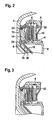
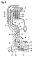
- FIGS. 2 and 3 the oil flow over the fins 4 is shown in detail.
- the sealing element 15 is caulked radially outward with the outer plate carrier 5.
- the radially inner end of the sealing element 15 rests resiliently on the end plate and thus prevents the inflow of the oil in the outer toothing region. Therefore, the oil flows over the inner toothed area (ie between the teeth of the inner plate carrier and the radially inner toothed plates 4). Since it is not possible to drain the oil to the lower left (see in the FIG.
- the oil can flow only radially outward. If the oil has reached the outer toothing area after the friction surfaces of the disks 4 (the friction surface usually has oil grooves), it can only flow off via the opening between the piston and the additional wall 19. Thus, the piston 14 does not close the opening, the piston is provided with circumferentially sequential "lugs" 26.
- the lugs 26 are supported here on the surface of the left lamella 4. In the spaces between the lugs 26, the oil can flow away undisturbed.
- FIG. 3 differs only in this respect to the FIG. 2 in that here the lock-up clutch 3 is closed. This becomes clear at the missing gap between the axial stop 22 and the adjacent lamella 4.
- the flow of oil takes place here in the course just as in the FIG. 2 , except that here by the compression of the fins 4, the oil flow - at a constant pressure in the space 8 - is reduced. However, this can be compensated by an increased pressure in the space 8 during slippage.
- the inventive solution in the FIG. 4 is opposite to the FIG. 1 to see a different arrangement of the piston.
- the inventive solutions are not dependent on these embodiments.
- the second innovative solution with the FIGS. 4 and 5 is to be shown, is that not the outer toothing region is sealed at the outer plate carrier 5, but that the radially outer region of the piston near lamella is well sealed so that here no oil between the radially outer fin surface and the ring-nose of the piston can flow , At the same time, however, the lamellae are provided with at least one axial bore 33.
- Boreholes 33 are preferably located in the radial middle region in the lamellae 4. If the oil has now taken its course in the manner described above and now reaches the bores, the oil then flows axially in the direction of the piston 14. Like in the FIG. 5 As can be clearly seen, the annular nose 26 of the piston 14 has recesses so that the oil can drain into the third space 16.
- FIG. 5 Yet another inventive idea is clearly visible:
- a rotation lock for the piston 14 can be seen, which riveted to the housing and is provided radially on the outside with slots, which engage in these slots webs 32.
- this rotation lock 30 is designed as a plate spring.
- the riveting could also be on the piston and the connection by means of slots and corresponding webs 32, also on the housing wall 2.
- the illustrated rotation lock also has another advantage: Through its radial extent to the transmission input shaft 29, the rotation lock 30 is also used as a thrust washer - ie as an axial sliding bearing - between the housing 2 and transmission input shaft 29th
- the additional wall 19 in turn connected sealingly with the slats.
- the peculiarity in this embodiment lies in the fact that the additional wall 19 extends into the outer toothing region of the lock-up clutch 3 and at the same time rests flat on the adjacent lamella. Engages the additional wall itself with teeth in the teeth of the outer disk carrier, so is a rotation lock 30 - as in the FIGS. 4 and 5 shown - not required because of the riveting 31 of the additional wall 19 with the piston 14 and the piston 14 is secured against rotation.
- the piston has a recess 34.
- This recess 34 may for example consist of a blind bore and a radially inwardly adjoining groove (as in the FIG. 6 shown). But also an arcuate groove is conceivable here.
- FIG. 6 to see that for an elastic compliance between the disk set and the piston position, between the radially outer and the radially inner Area of the additional wall 19 a soft connection zone 36 has been designed. This has been achieved by reducing the wall thickness in this area.
- the additional wall 19 has been designed as a disk-shaped spring element. It should be emphasized that this spring element seals the left blade both radially outward, and radially inward by conditioning. Because of the small wall thickness of the additional wall 19 shown in the FIG. 7 is not clear enough to recognize that here also a hole in the additional wall 19 is present, through which the oil in the recess 34, and then in the third space 16 can continue to flow.
- FIG. 8 shows a further embodiment of the additional wall 19, which is designed in two parts.
- the radially inner region 19a of the additional wall 19 is provided with a thicker wall thickness than the radially outer 19b.
- the radially outer portion 19b is preferably designed elastically and is also still with a spring force - preferably mit.einer plate spring 35 - pressurized.
- a plate spring 35 is advantageous because it allows the oil to drain through its slots in the third space 16 because of their partially radially slotted structure.
- the piston 14 with its nose 26 on the left lamella ie, the lock-up clutch 3 is at least partially actuated
- the lock-up clutch 3 is at least partially actuated
- the oil can not flow out of the space 8, without having flowed over the friction surfaces of the slats.
- the radially outer 19b and the radially inner portion 19a of the additional wall 19 - regardless of their current axial positions - remain sufficiently connected for their function, it is advantageous if both parts - at least rotationally fixed - are interconnected. This can be done for example by means of a shrink connection, riveting or caulking.
- the tightness between the radially outer 19b and the radially inner 19a portion of the additional wall 19 can be ensured by, for example, the portion 19b is pressed against a shoulder of the portion 19a, as it is also in the FIG. 8 is shown.
Landscapes
- Engineering & Computer Science (AREA)
- General Engineering & Computer Science (AREA)
- Mechanical Engineering (AREA)
- Control Of Fluid Gearings (AREA)
- Mechanical Operated Clutches (AREA)
- Massaging Devices (AREA)
- Devices For Conveying Motion By Means Of Endless Flexible Members (AREA)
Description
- Die Erfindung betrifft einen Drehmomentwandler mit einer Überbrückungskupplung, wobei diese Überbrückungskupplung mit mindestens zwei axial verschiebbaren Lamellen ausgestattet ist. Außerdem ist der Drehmomentwandler mit einem Drei-Kanal-System ausgerüstet. Zur Optimierung des Ölflusses, und damit zur besseren Kühlung der Lamellen, sind Maßnahmen vorgesehen, die den Ölstrom über die Lamellen erzwingen.
- Aus dem gattungsgemäßen der Technik ist die Schrift
DE 103 50 935 A1 bekannt, in der beschrieben ist, dass durch entsprechende Maßnahmen der Ölfluss über die Lamellen einer Wandler-Überbrückungskupplung optimiert werden kann. Hierzu wird in einem Bereich, der fern der Überbrückung ist, der Durchfluss-Widerstand für das Öl erhöht. In einer zweiten, unabhängigen Maßnahme wird der Durchfluss-Widerstand für das Öl über die Überbrückungskupplung reduziert. - Es ist Aufgabe der Erfindung, den Ölfluss über die Reibflächen der Lamellen einer Überbrückungskupplung weiter zu verbessern.
- Die Aufgabe wird dadurch gelöst, dass der zirkulierende Ölstrom im Bereich der hydrodynamischen Bauelemente (Pumpe, Turbine, Leitrad) nur noch über die Lamellen der Überbrückungskupplung zu- oder abfließen kann. Dieses wird erreicht, indem eine Zusatzwandung auf dem Kolben angebracht wird, wobei diese Zusatzwandung auf der Seite des Kolbens angebracht wird, die dem Lamellenpaket und damit dem Druckraum für den Kolben abgewandt ist. Das Ende der Zusatzwandung, welches nahe dem Lamellenpaket ist, ist im Wesentlichen öldicht an der Oberfläche der benachbarten Lamelle angelegt. Das Ende der Zusatzwandung, welches der Getriebeeingangswelle nahe ist, ist wiederum im Wesentlichen öldicht - aber drehbar - mit dieser verbunden.
- In einer ersten Ausgestaltung der Erfindung ist der äußere Verzahnungsbereich am äußeren Lamellenträger an seinem der Turbine zugewandten Ende im Wesentlichen öldicht verschlossen ist. Weiterhin ist im äußeren Verzahnungsbereich, an dem der Turbine abgewandten Ende, ein Kanal angeordnet, der einen Ölzufluss aus dem Bereich der hydrodynamischen Bauelemente im Wesentlichen unmöglich macht. Dadurch muss das Öl in seiner Zirkulation immer über die Lamellen fließen. Ist die Überbrückungskupplung geschlossen, so kann zwar das Öl nicht ungehindert zirkulieren, aber dann erfolgt ja die Drehmomentübertragung ausschließlich über die Kupplung. Mit anderen Worten: Die Pumpe und die Turbine laufen drehsynchron, wodurch dort keine Arbeit und damit auch keine Reibung erzeugt wird.
- Ist bei der erfindungsgemäßen Ausgestaltung die Überbrückungskupplung offen, d.h. es erfolgt eine hohe Wärmeentwicklung durch die Torusströmung in der Pumpe, Turbine und Leitrad, so kann die Zirkulation zum und vom Wandler, im vollen Umfang stattfinden.
- Ist die Überbrückungskupplung im Schlupfbetrieb, so entsteht die Wärme hauptsächlich an den Reibflächen der Lamellen. Durch die erfindungsgemäße Anordnung ist dann der Ölfluss optimal für die Kühlung der Lamellen ausgelegt..Mit anderen Worten: Die hier beschrieben Zwangführung des Öles stellt immer sicher, dass das Öl erst dann wieder das Wandler-Innere verlassen kann, wenn es seinen Weg über die Reiboberfläche der Lamellen genommen hat.
- In einer zweiten Ausgestaltung der Erfindung ist auch der äußere Verzahnungsbereich am äußeren Lamellenträger an seinem der Turbine zugewandten Ende nicht verschlossen. Dafür ist aber in dem Bereich zwischen Kolben und der benachbarten Lamelle ein Dichtungselement angeordnet, welches den radialen Bereich vom Außendurchmesser der Lamelle, hin zu axialen Bohrungen durch die Lamellen, abdichtet.
- Nachfolgend soll nun die Erfindung anhand der Figuren näher erläutet werden. Es zeigen:
- Figur 1
- einen Halbschnitt durch einen erfindungsgemäßen Drehmomentwandler, gemäß der ersten Lösung;
- Figur 2
- einen Ausschnitt aus
Figur 1 bei geöffneter Überbrückungskupplung; - Figur 3
- einen Ausschnitt aus
Figur 1 bei geschlossener oder schlupfender Überbrückungskupplung; - Figur 4
- einen Halbschnitt durch einen Wandler gemäß der zweiten Lösung;
- Figur 5
- einen Ausschnitt aus der
Figur 4 ; - Figur 6
- einen Halbschnitt gemäß der zweiten Lösung mit durchgängiger Zusatzwandung;
- Figur 7
- gemäß
Figur 6 , jedoch mit einer Zusatzwand als Federelement; - Figur 8
- einen Halbschnitt gemäß der zweiten Lösung, jedoch mit zweiteiliger Zusatzwand.
- In der
Figur 1 ist ein Drehmomentwandler 1 zu sehen, der sich um eine Rotationsachse 21 dreht. Der Wandler 1 weist in seinem Gehäuse 2 im Wesentlichen eine Pumpe 9, eine Turbine 10, ein Leitrad 11 und eine Überbrückungskupplung 3 auf. Im Kraftfluss zwischen der Überbrückungskupplung 3 und einer Nabe 25 ist auch ein Dämpfer 18 angeordnet. Die Getriebeeingangswelle und die Momentenabstützung für das Leitrad 11 wurden aus der Zeichnung herausgelassen. - Der Wandler verfügt über ein Drei-Kanal-System. D.h., dass insgesamt drei Kanäle vorhanden sind, um eine Ölzirkulation und das Steuern der Überbrückungskupplung 3 zu realisieren. Es wird hiermit vorausgestellt, dass der Ölstrom für die Zirkulation zwei Richtungen haben kann Die in der
Figur 1 gezeigte Richtung ist also nur exemplarisch und nicht beschränkend zu verstehen. Aus einen ersten Kanal 7, der zwischen dem hülsenförmigen Fortsatz am rechten Ende des Wandlers zu sehen ist und der nicht dargestellten Momentenstütze für das Leitrad 11, fließt das Öl zunächst in die Pumpe 9. Ein Teil des Öles vollzieht dann eine Fortsetzung der Torusströmung in der Turbine1 0 und dem Leitrad 11. Der andere Teil des Öles tritt an dem Spalt zwischen Pumpe 9 und Turbine 10 aus und ergießt sich in den restlichen Bereich des ersten Raumes 8. - Ein weiterer, zweiter Kanal 12 des Wandlers 1, der aus der hohlen Getriebeeingangswelle (nicht gezeigt) herausführt, versorgt einen zweiten Raum 13. Wird dieser Raum 13 durch Öldruck beaufschlagt, so schließt die Überbrückungskupplung 3, indem ein Kolben 14 nach rechts herüber fährt und dabei Lamellen 4 gegen einen axialen Anschlag 22 presst. Ist der zweite Raum 13 jedoch drucklos oder nur gering mit Druck beaufschlagt, so presst der Öldruck aus dem ersten Raum 8 wieder auf.
- Die Lamellen 4 greifen mit ihren Verzahnungen abwechselt in die Verzahnungen eines äußeren Lamellenträgers 5 oder eines inneren Lamellenträgers 6. Erfindungsgemäß ist an dem äußeren Lamellenträger 5, an seinem der Turbine 10 zugewandten Ende mit einem Dichtelement 15. versehen. Dieses Dichtelement 15 macht einen Ölfluss zwischen den Zähnen des äußeren Lamellenträgers 5 und den Zähnen der außen eingreifenden Lamellen 4 im Wesentlichen unmöglich, weil es sowohl auf dem stirnseitigen Rand des äußeren Lamellenträger dichtend, als auch auf der rechten Lamelle - der so genannten Endlamelle - aufliegt. Das Dichtelement 15 ist in dem Ausführuhgsbeispiel als ringförmige Feder ausgestaltet, es kann aber auch im Rahmen der Erfindung als Ringscheibe ausgebildet sein, wobei dann die Ringscheibe zugleich auch als axialer Anschlag 22 dienen kann. Das Dichtelement 15 kann mittels Schweißen oder Verstemmen (einer Art Nieten) an dem äußeren Lamellenträger 5, an dem Gehäuse 2 oder auch an einem Ausgangsteil eines radial außen angeordneten Dämpfers befestigt sein.
- Zur Erfindung gehört aber auch noch ein dritter Kanal 17, der mit einem Raum 16 verbunden ist. Dieser Raum 16 wird beispielsweise gebildet, indem auf dem Kolben 14 mittels Distanzniete 24 eine Zusatzwandung 19 angeordnet wird. Der Spalt 20 zwischen dem Kolben 14 und der Zusatzwandung 19 hat auf dem der Turbine abgewandten Ende des äußeren Verzahnungsbereiches eine Öffnung, die das zirkulierende Öl aufnehmen kann. Da die Zusatzwandung gegenüber der Nabe 25 abdichtet, kann aus dem ersten Raum 8 kein Öl in den Rücklauf (= dritter Kanal) hineindrücken. Somit ist sichergestellt, dass im Wesentlichen das Öl nur über die Lamellen 4, bzw. über die Überbrückungskupplung 3 zirkulieren kann. Dadurch wird die Kühlung der Reibbeläge der Lamellen 4 optimiert.
- Mit den
Figuren 2 und 3 wird der Ölfluss über die Lamellen 4 im Detail gezeigt. Man kann in derFigur 2 an dem Spalt zwischen dem axialen Anschlag 22 und der dazu benachbarten Lamelle 4 erkennen, dass hier die Überbrückungskupplung nicht geschlossen ist. Das Dichtelement 15 ist radial außen mit dem äußeren Lamellenträger 5 verstemmt. Das radial innere Ende des Dichtelementes 15 liegt federnd auf der Endlamelle auf und verhindert so das Einströmen des Öles im äußeren Verzahnungsbereich. Deshalb fließt das Öl über den inneren Verzahnungsbereich (also zwischen denn Zähnen des inneren Lamellenträgers und den radial innen verzahnten Lamellen 4). Da ein Abfließen des Öles nach links unten nicht möglich ist (siehe in derFigur 1 die Dichtstelle zwischen der Zusatzwandung 19 und der ringförmigen Anformung an der Nabe 25), kann das Öl nur radial nach außen fließen. Ist das Öl nach dem Überstreifen der Reibflächen der Lamellen 4 (die Reibfläche besitzen üblicherweise Ölnute) im äußeren Verzahnungsbereich angekommen, so kann es nur noch über die Öffnung zwischen dem Kolben und der Zusatzwandung 19 abfließen. Damit der Kolben 14 nicht die Öffnung zudrückt, ist der Kolben mit umfänglich sequentiellen "Nasen" 26 versehen. Die Nasen 26 stützen sich hierbei auf der Oberfläche der linken Lamelle 4 ab. In den Zwischenräumen zwischen den Nasen 26 kann das Öl ungestört abfließen. - Die
Figur 3 unterscheidet sich nur darin gegenüber derFigur 2 , dass hier die Überbrückungskupplung 3 geschlossen ist. Dieses wird an dem fehlenden Spalt zwischen dem axialen Anschlag 22 und der benachbarten Lamelle 4 deutlich. Der Ölfluss erfolgt hier in seinem Verlauf genau so wie in derFigur 2 , nur dass hier durch das Zusammenpressen der Lamellen 4, der Ölfluss - bei gleich bleibendem Druck in dem Raum 8 - reduziert ist. Dieses kann aber durch einen erhöhten Druck im Raum 8 während des Schlupfens kompensiert werden. Unabhängig von der erfinderischen Lösung in derFigur 4 , ist gegenüber derFigur 1 , eine andere Anordnung des Kolbens zu sehen. Bei derFigur 4 ist der Kolben 14 auf der Getriebeeingangswelle und nicht wie in derFigur 1 , auf einer so genannten deckelfesten Nabe angeordnet. Die erfinderischen Lösungen sind aber nicht von diesen Ausgestaltungen abhängig. - Die zweite erfinderische Lösung, die mit den
Figuren 4 und5 gezeigt werden soll, besteht darin, dass nicht der äußere Verzahnungsbereich am äußeren Lamellenträger 5 abgedichtet wird, sondern dass der radial äußere Bereich der kolbennahen Lamelle gut abgedichtet wird, damit hier kein Öl zwischen der radial äußeren Lamellenoberfläche und der Ring-Nase des Kolben abströmen kann. Gleichzeitig sind aber die Lamellen mit mindestens einer axialen Bohrung 33 versehen. Strömt nun aufgrund der Druckunterschiede zwischen dem ersten Raum 8 und dem dritten Raum 16 Öl in den Verzahnungsbereich zwischen den Lamellen (4) und dem äußerem Lamellenträger 5 und/oder dem Lamellenträger 6, so kann das Öl nur in radialer Richtung in dem Spalt zwischen den Reibbelägen und den Oberflächen der reibbelagslosen Lamellen - mit oder auch ohne Hilfe von Ölnuten in den Reibbelägen bzw. den Stahllamellen - fließen. Ausdrücklich soll hier hervorgehoben werden, dass die Endlamelle 27, also die Lamelle, die der Turbine am nahesten ist, nicht durchbohrt ist, weil sonst - wie man aus den Figuren leicht entnehmen kann - kein Ölfluss über die Reibflächen der Lamellen entstehen würde. - Vorzugsweise im radial mittleren Bereich befinden sich in den Lamellen 4 Bohrungen 33. Hat das Öl nun in der oben beschriebenen Weise seinen Weg eingeschlagen und gelangt nun zu den Bohrungen, so das Öl dann axial in Richtung Kolben 14 fließen. Wie in der
Figur 5 gut zu sehen ist, weist die ringförmige Nase 26 des Kolbens 14 Aussparungen auf, so dass das Öl in den dritten Raum 16 abfließen kann. - In den
Figuren 4 und5 ist auch eine Einschubhülse 28 zu sehen, die den dritten Kanal 17 um die Verzahnung zwischen der Nabe 25 mit der Getriebeeingangswelle 29 herumführen muss. Dieser Verzahnungsbereich ist sehr passgenau gefertigt, wodurch ein Öldurchfluss hier sehr erschwert wird. In derFigur 1 ist diese Einschubhülse nicht erforderlich, weil dort der Ölfluss radial außerhalb der Verzahnung Nabe/Getriebewetienach rechts - also Richtung Getriebe - geführt wird. - Es soll nicht unerwähnt bleiben, dass sowohl in der ersten Ausgestaltung der Erfindung - dargestellt mit den
Figuren 1 bis 3 , als auch in der zweiten Ausgestaltung der Erfindung - dargestellt mit denFiguren 4 und5 - der Ölfluss auch in umgekehrter Richtung fließen kann, ohne dass hier der erfindungsgemäße Gedanke verlassen wird. - In der
Figur 5 wird auch noch ein weiterer erfinderischer Gedanke gut sichtbar: Hier ist eine Drehsicherung für den Kolben 14 zu sehen, die mit dem Gehäuse vernietet und radial außen mit Schlitzen versehen ist, wobei in diese Schlitze Stege 32 eingreifen. Vorzugsweise ist diese Drehsicherung 30 als Tellerfeder ausgestaltet. Im Rahmen dieser Erfindung könnte die Vernietung auch an dem Kolben und die Verbindung mittels Schlitzen und entsprechenden Stegen 32, auch an der Gehäusewandung 2 sein. - Die dargestellte Drehsicherung hat aber auch noch einen weiteren Vorteil: Durch ihre radiale Erstreckung hin zur Getriebeeingangswelle 29 dient die Drehsicherung 30 auch als Anlaufscheibe - also als axiale Gleitlagerung - zwischen Gehäuse 2 und Getriebeeingangswelle 29.
- In der
Figur 6 ist die Zusatzwand 19 wiederum dichtend mit den Lamellen verbunden. Die Besonderheit in dieser Ausgestaltung liegt aber hier darin, dass die Zusatzwand 19 sich bis in den äußeren Verzahnungsbereich der Überbrückungskupplung 3 erstreckt und zugleich flächig auf der benachbarten Lamelle aufliegt. Greift die Zusatzwand selber mit Zähnen in die Verzahnung des äußeren Lamellenträgers ein, so ist eine Drehsicherung 30 - wie in denFiguren 4 und5 gezeigt - nicht erforderlich, da durch die Vernietung 31 der Zusatzwand 19 mit dem Kolben 14 auch der Kolben 14 drehgesichert ist. - Damit das Öl die Lamellen mittels der Bohrung 33 durchströmen kann, muss in dem Beispiel der
Figur 6 auch die Zusatzwand 19 in dem Bereich eine Bohrung aufweisen. Um eine hydraulische Verbindung zum dritten Raum 16 herzustellen, weist der Kolben eine Ausnehmung 34 auf. Diese Ausnehmung 34 kann beispielsweise aus einer Sackbohrung und einer sich radial nach innen anschließenden Nut bestehen (wie in derFigur 6 gezeigt). Aber auch eine bogenförmige Nut ist hier denkbar. - Ferner ist der
Figur 6 zur entnehmen, dass für eine elastische Nachgiebigkeit zwischen dem Lamellenpaket und der Kolbenstellung, zwischen dem radial äußeren und dem radial inneren Bereich der Zusatzwand 19 eine weiche Anbindungszone 36 gestaltet wurde. Dieses ist durch eine Reduzierung der Wandstärke in diesem Bereich erzielt worden. - In der
Figur 7 ist die Zusatzwand 19 als scheibenförmiges Federelement ausgebildet worden. Hierbei ist hervorzuheben, dass dieses Federelement die linke Lamelle sowohl radial außen, als auch radial innen durch Anlage abdichtet. Wegen der geringen Wandstärke der dort gezeigten Zusatzwand 19 in derFigur 7 ist nicht deutlich genug zu erkennen, dass auch hier eine Bohrung in der Zusatzwand 19 vorhanden ist, durch die das Öl in die Ausnehmung 34, und dann in den dritten Raum 16 weiter fließen kann. - Die
Figur 8 zeigt eine weitere Ausgestaltung der Zusatzwand 19, die zweiteilig ausgestaltet ist. Der radial innere Bereich 19a der Zusatzwand 19 ist mit einer dickeren Wandstärke versehen, als der radial äußere 19b. Der radial äußere Bereich 19b ist vorzugsweise elastisch ausgestaltet und wird auch noch mit einer Federkraft - vorzugsweise mit.einer Tellerfeder 35 - druckbeaufschlagt. Eine Tellerfeder 35 ist deshalb vorteilhaft, weil sie wegen ihrer teilweise radial geschlitzten Struktur das Öl durch ihre Schlitze in den dritten Raum 16 abfließen lässt. - Liegt bei dem Ausführungsbeispiel der
Figur 8 der Kolben 14 mit seiner Nase 26 an der linken Lamelle an (d.h. die Überbrückungskupplung 3 ist zumindest teilweise betätigt), so durch die ebenfalls anliegende Zusatzwand 19b ein eindeutiger Abfluss des Öles definiert. Mit anderen Worten: das Öl kann nicht aus dem Raum 8 abfließen, ohne über die Reibflächen der Lamellen geflossen zu sein. - Damit das radial äußere 19b und das radial innere 19a Teilstück der Zusatzwand 19 - unabhängig von ihren momentanen axialen Stellungen - für ihre Funktion in ausreichender Weise verbunden bleiben, ist es vorteilhaft, wenn beide Teile - zumindest drehfest - miteinander verbunden werden. Dieses kann beispielsweise mittels einer Schrumpfverbindung, Vernieten oder auch Verstemmen geschehen. Die Dichtheit zwischen dem radial äußeren 19b und dem radial inneren 19a Teilstück der Zusatzwand 19 kann gewährleistet werden, indem beispielsweise das Teilstück 19b gegen einen Absatz des Teilstückes 19a gedrückt wird, wie es auch in der
Figur 8 dargestellt ist. - Um unnötige Wiederholungen in den Figurenbeschreibungen zu vermeiden, wurden für gleiche Bauteile in den Zeichnungen auch gleiche Bezugszeichen verwendet.
-
- 1
- Drehmomentwandler/Wandler
- 2
- Wandler-Gehäuse.
- 3
- Überbrückungskupplung
- 4
- Lamelle
- 5
- äußerer Lamellenträger
- 6
- innerer Lamellenträger
- 7
- erster Kanal
- 8
- erster Raum
- 9
- Pumpe
- 10
- Turbine
- 11
- Leitrad
- 12
- zweiter Kanal
- 13
- zweiter Raum
- 14
- Kolben
- 15
- Dichtelement
- 16
- dritter Raum
- 17
- dritter Kanal
- 18
- Dämpfer
- 19
- Zusatzwandung
- 20
- Spalt
- 21
- Rotationsachse
- 22
- axialer Anschlag; Sicherungsring
- 23
- Dichtung
- 24
- Distanzniet
- 25
- Nabe
- 26
- Nase
- 27
- Endlamelle
- 28
- Einschubhülse
- 29
- Getriebeeingangswelle
- 30
- Drehsicherung des Kolbens
- 31
- Niet
- 32
- Steg
- 33
- Bohrung34 Ausnehmung im Kolben
- 35
- Tellerfeder
- 36
- weiche Anbindungszone
Claims (20)
- Drehmomentwandler (1), insbesondere für Kraftfahrzeuge, mit einem Drei-Kanal-Ölsystem und einer Überbrückungskupplung (3) mit den folgenden Merkmalen:- die Überbrückungskupplung (3) weist mindestens zwei axial verschiebbare Lamellen (4) auf, wobei mindestens eine Lamelle (4) mit einem äußeren Lamellenträger (5) und mindestens eine andere Lamelle (4) mit einem inneren Lamellenträger (6) drehfest verbunden ist,- ein erster Kanal (7) des Ölsystems ist mit einem ersten Raum (8) verbunden, der unter anderem die hydrodynamischen Komponenten des Wandlers (1) - wie Pumpe (9), Turbine (10) und Leitrad (11) - aufnimmt,- ein zweiter Kanal (12) betätigt die Überbrückungskupplung (3), indem ein zweiter Raum (13) des Wandlers (1) mit Öldruck beaufschlagt und dadurch ein Kolben (14) gegen die Lamellen (4) gepresst wird,gekennzeichnet durch eine zum Kolben beabstandete Zusatzwandung (19), die auf der Seite des Kolbens (14) angebracht ist, die dem ersten Raum (8) zugewandt ist, wodurch ein Spalt (20) zwischen Kolben und Zusatzwandung (19) entsteht, wobei die Zusatzwandung (19) im Wesentlichen öldicht an der dem Kolben (14) zugewandten Lamelle (4) anliegt und zugleich eine hydraulische Trennung zum ersten Raum (8) und zum zweiten Raum (13) herstellt, wodurch ein dritter Raum (16) entsteht, und wobei der dritte Raum (16) im Wesentlichen öldicht mit einem dritten Kanal (17) verbunden ist.
- Wandler nach Anspruch 1, dadurch gekennzeichnet, dass von dem Öl zunächst der erste Raum (8) und dann erst der dritte Raum (16) durchströmt wird.
- Wandler nach Anspruch 1, dadurch gekennzeichnet, dass von dem Öl zunächst der dritte Raum (16) und dann erst der erste Raum (8) durchströmt wird.
- Wandler nach einem der Ansprüche 1 bis 3, dadurch gekennzeichnet, dass in dem ersten Raum (8) mindestens ein Dämpfer (18) angeordnet ist.
- Wandler nach einem der Ansprüche 1 bis 4, dadurch gekennzeichnet, dass ein Dichtelement (15) derart angebracht ist, dass der Ölfluss zwischen dem äußeren Lamellenträger (5) und den Verzahnungen der dem ersten Raum (8) zugewandten Lamelle (4) zumindest reduziert.
- Wandler nach Anspruch 5, dadurch gekennzeichnet, dass das Dichtelement (15) als ringförmige Feder ausgestaltet ist.
- Wandler nach Anspruch 5 oder 6, dadurch gekennzeichnet, dass das Dichtelement (15) als Ringscheibe ausgestaltet ist, wobei die Ringscheibe zugleich als axialer Anschlag (22) für die Lamellen (4) dient.
- Wandler nach einem der Ansprüche 5 bis 7, dadurch gekennzeichnet, dass das Dichtelement (15) mit dem äußeren Lamellenträger (5) öldicht verbunden ist.
- Wandler nach einem der Ansprüche 5 oder 6, dadurch gekennzeichnet, dass das Dichtelement (15) mit dem Wandlergehäuse (2) öldicht verbunden ist.
- Wandler nach einem der Ansprüche 5 bis 9, dadurch gekennzeichnet, dass das Dichtelement (15) mittels Schweißen verbunden wird.
- Wandler nach einem der Ansprüche 5 bis 9, dadurch gekennzeichnet, dass das Dichtelement (15) mittels Verstemmen verbunden wird
- Wandler nach Anspruch 11, dadurch gekennzeichnet, dass die Zusatzwandung (19) partiell mit Erhebungen versehen ist, die nach dem Montieren mit dem Kolben (14) auf dem Kolben (14) aufliegen.
- Wandler nach einem der Ansprüche 1 bis 12, dadurch gekennzeichnet, dass der dritte Raum (16) dadurch gebildet wird, dass der Kolben (14) - zumindest teilweise - hohl gestaltet ist, wodurch ein Ölfluss zwischen den Lamellen (4) und dem dritten Kanal (17) möglich wird.
- Wandler nach einem der Ansprüche 1 bis 4, dadurch gekennzeichnet, dass die Lamellen (4) und die darauf angeordneten Reibbeläge - außer der Endlamelle (27) - mit mindestens einer axial orientierten Bohrung (33) versehen sind.
- Wandler nach Anspruch 14, dadurch gekennzeichnet, dass die Bohrung (33) im Wesentlichen auf dem mittleren Durchmesser der Reibbeläge angeordnet ist.
- Wandler nach Anspruch 14 oder 15, dadurch gekennzeichnet, dass ein Dichtelement (15) zwischen der dem Kolben (14) zugewandeten Lamelle (4) und dem Kolben (14) derart angebracht ist, dass ein Ölfluss zwischen dem Kolben (14) und der dem Kolben (14) zugewandten Lamelle (4) im Bereich zwischen dem Außendurchmesser der Lamelle (4) und der Bohrung (33) zumindest reduziert wird.
- Wandler nach Anspruch 16, dadurch gekennzeichnet, dass das Dichtelement (15) als Kegelscheibe ausgebildet ist.
- Wandler nach Anspruch 14 oder 15, dadurch gekennzeichnet, dass die Zusatzwand (19) bis zum äußeren Verzahnungsbereich der Überbrückungskupplung (3) ausgeführt wird, die Bohrung (33) in diesem Bereich auch durch die Zusatzwand (19) hindurchgeht, wodurch das Öl über eine Ausnehmung (34) in dem Kolben (14) in den dritten Raum (16) abfließen kann.
- Wandler nach Anspruch 18, dadurch gekennzeichnet, dass die Zusatzwand (19) als scheibenförmiges Federelement ausgebildet ist.
- Wandler nach einem der Ansprüche 14 bis 19, dadurch gekennzeichnet, dass die Zusatzwand (19) aus zwei Teilkomponenten (19a, 19b) besteht.
Applications Claiming Priority (3)
| Application Number | Priority Date | Filing Date | Title |
|---|---|---|---|
| US75830206P | 2006-01-12 | 2006-01-12 | |
| DE102006055229 | 2006-11-21 | ||
| PCT/DE2006/002317 WO2007079713A2 (de) | 2006-01-12 | 2006-12-27 | Wandler mit zwangs-ölführung |
Publications (3)
| Publication Number | Publication Date |
|---|---|
| EP1977141A2 EP1977141A2 (de) | 2008-10-08 |
| EP1977141B1 true EP1977141B1 (de) | 2009-11-18 |
| EP1977141B2 EP1977141B2 (de) | 2014-01-01 |
Family
ID=46045580
Family Applications (1)
| Application Number | Title | Priority Date | Filing Date |
|---|---|---|---|
| EP06846948.5A Ceased EP1977141B2 (de) | 2006-01-12 | 2006-12-27 | Wandler mit zwangs-ölführung |
Country Status (6)
| Country | Link |
|---|---|
| EP (1) | EP1977141B2 (de) |
| JP (1) | JP5126067B2 (de) |
| CN (1) | CN101356389B (de) |
| AT (1) | ATE449273T1 (de) |
| DE (2) | DE202006020596U1 (de) |
| WO (1) | WO2007079713A2 (de) |
Cited By (2)
| Publication number | Priority date | Publication date | Assignee | Title |
|---|---|---|---|---|
| EP1975467A2 (de) | 2007-03-26 | 2008-10-01 | ZF Friedrichshafen AG | Hydrodynamische Kopplungsvorrichtung |
| WO2018164555A1 (en) * | 2017-03-10 | 2018-09-13 | Valeo Kapec Co., Ltd. | Hydrokinetic torque coupling device with centered lock-up clutch |
Families Citing this family (21)
| Publication number | Priority date | Publication date | Assignee | Title |
|---|---|---|---|---|
| DE102007005999A1 (de) * | 2006-04-07 | 2007-10-11 | Zf Friedrichshafen Ag | Fluidbefüllte Kopplungsanordnung |
| DE102007052484B4 (de) * | 2006-11-29 | 2018-09-20 | Schaeffler Technologies AG & Co. KG | Drehmomentübertragungseinrichtung |
| DE112007002931A5 (de) * | 2006-12-27 | 2009-09-10 | Luk Lamellen Und Kupplungsbau Beteiligungs Kg | Kraftübertragungsvorrichtung und Lagerscheibe, insbesondere Axialgleitlagerscheibe |
| WO2008077376A2 (de) * | 2006-12-27 | 2008-07-03 | Luk Lamellen Und Kupplungsbau Beteiligungs Kg | Kraftübertragungsvorrichtung |
| DE102008020683B4 (de) | 2007-05-09 | 2019-01-17 | Schaeffler Technologies AG & Co. KG | Drehmomentwandler mit Anordnung für Kühlfluidströmung und Anordnung zur Drehmomentübertragung auf einen Dämpfer |
| DE102008057657A1 (de) * | 2007-12-10 | 2009-06-18 | Luk Lamellen Und Kupplungsbau Beteiligungs Kg | Kraftübertragungsvorrichtung |
| DE102009024744C5 (de) | 2008-06-26 | 2026-02-26 | Schaeffler Technologies AG & Co. KG | Kraftübertragungsvorrichtung |
| DE102009051223A1 (de) * | 2008-11-10 | 2010-05-12 | Luk Lamellen Und Kupplungsbau Beteiligungs Kg | Nasskupplung |
| DE102009051723A1 (de) | 2008-11-10 | 2010-05-12 | Luk Lamellen Und Kupplungsbau Beteiligungs Kg | Hydrodynamischer Drehmomentwandler mit Überbrückungskupplung |
| JP5617806B2 (ja) * | 2011-09-29 | 2014-11-05 | アイシン・エィ・ダブリュ株式会社 | 流体伝達装置 |
| JP5609897B2 (ja) * | 2012-01-16 | 2014-10-22 | マツダ株式会社 | トルクコンバータ |
| DE102013208197A1 (de) | 2013-05-06 | 2014-11-06 | Schaeffler Technologies Gmbh & Co. Kg | Reibkupplung |
| DE102013222213A1 (de) * | 2013-10-31 | 2015-04-30 | Zf Friedrichshafen Ag | Schaltelement eines Automatgetriebes für Kraftfahrzeuge |
| DE112015006040T5 (de) * | 2015-01-23 | 2017-12-07 | Schaeffler Technologies AG & Co. KG | Laufradgehäuse mit verstärkter Übergangsstelle und Verfahren zu dessen Herstellung |
| FR3053091B1 (fr) * | 2016-06-23 | 2019-12-20 | Valeo Embrayages | Embrayage hydrocinetique pour un vehicule automobile |
| KR102069527B1 (ko) * | 2018-05-16 | 2020-01-23 | 주식회사 카펙발레오 | 차량용 토크 컨버터 |
| US11067157B2 (en) * | 2019-07-11 | 2021-07-20 | Schaeffler Technologies AG & Co. KG | Torque converter clutch system |
| DE102020208351A1 (de) | 2020-07-03 | 2022-01-05 | Zf Friedrichshafen Ag | Hydrodynamischer Drehmomentwandler |
| DE102020208352A1 (de) | 2020-07-03 | 2022-01-05 | Zf Friedrichshafen Ag | Hydrodynamischer Drehmomentwandler mit einer Torsionsdämpferwandung |
| DE102020212758A1 (de) | 2020-10-08 | 2022-04-14 | Volkswagen Aktiengesellschaft | Kupplung, insbesondere Doppelkupplung für ein Kraftfahrzeug |
| DE102020216031A1 (de) | 2020-12-16 | 2022-06-23 | Zf Friedrichshafen Ag | Hydrodynamischer Drehmomentwandler |
Citations (1)
| Publication number | Priority date | Publication date | Assignee | Title |
|---|---|---|---|---|
| EP1843062A2 (de) * | 2006-04-07 | 2007-10-10 | Zf Friedrichshafen Ag | Fluidbefüllte Kopplungsanordnung |
Family Cites Families (11)
| Publication number | Priority date | Publication date | Assignee | Title |
|---|---|---|---|---|
| JPH05126229A (ja) * | 1991-03-30 | 1993-05-21 | Aisin Seiki Co Ltd | ロツクアツプクラツチ付自動変速機のひきずり防止装置 |
| JP3854661B2 (ja) * | 1996-05-29 | 2006-12-06 | 株式会社エクセディ | ロックアップ装置付きトルクコンバータ |
| FR2762657B1 (fr) * | 1997-04-29 | 1999-05-28 | Valeo | Appareil d'accouplement hydrocinetique dote de moyens elastiques anti-bruit, notamment pour vehicule automobile |
| JP3715114B2 (ja) * | 1998-09-09 | 2005-11-09 | 株式会社エクセディ | トルクコンバータ |
| DE10117746B4 (de) † | 2000-04-28 | 2017-06-29 | Schaeffler Technologies AG & Co. KG | Drehmomentübertragungseinrichtung |
| FR2811049B1 (fr) * | 2000-06-29 | 2002-10-11 | Valeo | Appareil d'accouplement hydrocinetique, notamment pour vehicule automobile, comportant des moyens perfectionnes de liaison du piston au couvercle |
| DE10104346A1 (de) * | 2001-02-01 | 2002-08-08 | Zahnradfabrik Friedrichshafen | Hydrodynamischer Drehmomentwandler |
| FR2843433B1 (fr) * | 2002-08-06 | 2005-04-01 | Valeo Embrayages | Appareil d'accouplement hydrocinetique, notamment pour un vehicule automobile |
| JP2004116611A (ja) * | 2002-09-25 | 2004-04-15 | Exedy Corp | 流体式トルク伝達装置のロックアップ装置 |
| DE10350935B4 (de) * | 2002-11-16 | 2019-02-21 | Schaeffler Technologies AG & Co. KG | Drehmomentwandler |
| DE10314325B4 (de) * | 2003-03-28 | 2011-01-27 | Zf Friedrichshafen Ag | Hydrodynamischer Wandler mit einer Primärkupplung |
-
2006
- 2006-12-27 AT AT06846948T patent/ATE449273T1/de not_active IP Right Cessation
- 2006-12-27 EP EP06846948.5A patent/EP1977141B2/de not_active Ceased
- 2006-12-27 DE DE202006020596U patent/DE202006020596U1/de not_active Expired - Lifetime
- 2006-12-27 WO PCT/DE2006/002317 patent/WO2007079713A2/de not_active Ceased
- 2006-12-27 JP JP2008549755A patent/JP5126067B2/ja not_active Expired - Fee Related
- 2006-12-27 CN CN2006800508811A patent/CN101356389B/zh not_active Expired - Fee Related
- 2006-12-27 DE DE112006003320T patent/DE112006003320B4/de not_active Expired - Fee Related
Patent Citations (1)
| Publication number | Priority date | Publication date | Assignee | Title |
|---|---|---|---|---|
| EP1843062A2 (de) * | 2006-04-07 | 2007-10-10 | Zf Friedrichshafen Ag | Fluidbefüllte Kopplungsanordnung |
Cited By (4)
| Publication number | Priority date | Publication date | Assignee | Title |
|---|---|---|---|---|
| EP1975467A2 (de) | 2007-03-26 | 2008-10-01 | ZF Friedrichshafen AG | Hydrodynamische Kopplungsvorrichtung |
| EP1975467A3 (de) * | 2007-03-26 | 2011-08-10 | ZF Friedrichshafen AG | Hydrodynamische Kopplungsvorrichtung |
| WO2018164555A1 (en) * | 2017-03-10 | 2018-09-13 | Valeo Kapec Co., Ltd. | Hydrokinetic torque coupling device with centered lock-up clutch |
| US11143280B2 (en) | 2017-03-10 | 2021-10-12 | Valeo KAPEC Co. Ltd. | Hydrokinetic torque coupling device with centered lock-up clutch |
Also Published As
| Publication number | Publication date |
|---|---|
| WO2007079713A3 (de) | 2007-11-15 |
| DE112006003320A5 (de) | 2008-09-18 |
| EP1977141A2 (de) | 2008-10-08 |
| DE112006003320B4 (de) | 2012-04-26 |
| CN101356389B (zh) | 2011-08-31 |
| WO2007079713A2 (de) | 2007-07-19 |
| DE202006020596U1 (de) | 2009-03-19 |
| CN101356389A (zh) | 2009-01-28 |
| ATE449273T1 (de) | 2009-12-15 |
| EP1977141B2 (de) | 2014-01-01 |
| JP5126067B2 (ja) | 2013-01-23 |
| JP2009523219A (ja) | 2009-06-18 |
Similar Documents
| Publication | Publication Date | Title |
|---|---|---|
| EP1977141B2 (de) | Wandler mit zwangs-ölführung | |
| DE10350935B4 (de) | Drehmomentwandler | |
| EP2470808B1 (de) | Doppelkupplungsanordnung für ein getriebe mit zwei eingangswellen | |
| DE10352963B4 (de) | Wandler | |
| EP3186525B1 (de) | Doppelkupplung | |
| EP1482195B1 (de) | Kupplungsvorrichtung und Verfahren zum Betreiben einer Lamellenkupplung | |
| EP3207295B1 (de) | Ventileinrichtung | |
| EP2546547A1 (de) | Fluidbefüllte Kopplungsanordnung | |
| DE102007014311A1 (de) | Hydrodynamische Kopplungsvorrichtung | |
| WO2012045297A1 (de) | Doppelkupplung | |
| EP3880545A1 (de) | Konuselement als kupplung im k0-bauraum | |
| DE102008036852A1 (de) | Mehrfach-Kupplungseinrichtung mit Fliehölausgleich | |
| DE102009051223A1 (de) | Nasskupplung | |
| DE102008060940A1 (de) | Wandlervorrichtung | |
| EP1870610B1 (de) | Hebelsystem sowie Verfahren zu dessen Montage | |
| EP2742252B1 (de) | Stator für eine reibungskupplung | |
| DE102014217277A1 (de) | Doppelkupplung | |
| EP2837845B1 (de) | Reiblamellensystem und Reibkupplung mit einem solchen Reiblamellensystem | |
| EP2957790B1 (de) | Druckbegrenzungseinrichtung in einer hydraulischen strecke | |
| DE19549617C2 (de) | Hydrodynamischer Drehmomentwandler mit Überbrückungskupplung | |
| EP3645905B1 (de) | Kupplungsanordnung | |
| DE102009024744A1 (de) | Kraftübertragungsvorrichtung | |
| DE112009002560B4 (de) | Hydrodynamischer Drehmomentwandler mit Überbrückungskupplung | |
| DE19509500B4 (de) | Hydrodynamischer Drehmomentwandler und Befestigung einer Wälzlagereinheit an einem Rad eines Drehmomentwandlers | |
| AT513976B1 (de) | Schaltbare Zahnradpumpe |
Legal Events
| Date | Code | Title | Description |
|---|---|---|---|
| PUAI | Public reference made under article 153(3) epc to a published international application that has entered the european phase |
Free format text: ORIGINAL CODE: 0009012 |
|
| 17P | Request for examination filed |
Effective date: 20080812 |
|
| AK | Designated contracting states |
Kind code of ref document: A2 Designated state(s): AT BE BG CH CY CZ DE DK EE ES FI FR GB GR HU IE IS IT LI LT LU LV MC NL PL PT RO SE SI SK TR |
|
| 17Q | First examination report despatched |
Effective date: 20081030 |
|
| GRAP | Despatch of communication of intention to grant a patent |
Free format text: ORIGINAL CODE: EPIDOSNIGR1 |
|
| GRAS | Grant fee paid |
Free format text: ORIGINAL CODE: EPIDOSNIGR3 |
|
| GRAA | (expected) grant |
Free format text: ORIGINAL CODE: 0009210 |
|
| AK | Designated contracting states |
Kind code of ref document: B1 Designated state(s): AT BE BG CH CY CZ DE DK EE ES FI FR GB GR HU IE IS IT LI LT LU LV MC NL PL PT RO SE SI SK TR |
|
| REG | Reference to a national code |
Ref country code: GB Ref legal event code: FG4D Free format text: NOT ENGLISH |
|
| REG | Reference to a national code |
Ref country code: CH Ref legal event code: EP |
|
| REG | Reference to a national code |
Ref country code: IE Ref legal event code: FG4D |
|
| REF | Corresponds to: |
Ref document number: 502006005429 Country of ref document: DE Date of ref document: 20091231 Kind code of ref document: P |
|
| REG | Reference to a national code |
Ref country code: NL Ref legal event code: VDEP Effective date: 20091118 |
|
| LTIE | Lt: invalidation of european patent or patent extension |
Effective date: 20091118 |
|
| PG25 | Lapsed in a contracting state [announced via postgrant information from national office to epo] |
Ref country code: IS Free format text: LAPSE BECAUSE OF FAILURE TO SUBMIT A TRANSLATION OF THE DESCRIPTION OR TO PAY THE FEE WITHIN THE PRESCRIBED TIME-LIMIT Effective date: 20100318 Ref country code: FI Free format text: LAPSE BECAUSE OF FAILURE TO SUBMIT A TRANSLATION OF THE DESCRIPTION OR TO PAY THE FEE WITHIN THE PRESCRIBED TIME-LIMIT Effective date: 20091118 Ref country code: SE Free format text: LAPSE BECAUSE OF FAILURE TO SUBMIT A TRANSLATION OF THE DESCRIPTION OR TO PAY THE FEE WITHIN THE PRESCRIBED TIME-LIMIT Effective date: 20091118 Ref country code: PT Free format text: LAPSE BECAUSE OF FAILURE TO SUBMIT A TRANSLATION OF THE DESCRIPTION OR TO PAY THE FEE WITHIN THE PRESCRIBED TIME-LIMIT Effective date: 20100318 Ref country code: LT Free format text: LAPSE BECAUSE OF FAILURE TO SUBMIT A TRANSLATION OF THE DESCRIPTION OR TO PAY THE FEE WITHIN THE PRESCRIBED TIME-LIMIT Effective date: 20091118 Ref country code: ES Free format text: LAPSE BECAUSE OF FAILURE TO SUBMIT A TRANSLATION OF THE DESCRIPTION OR TO PAY THE FEE WITHIN THE PRESCRIBED TIME-LIMIT Effective date: 20100228 |
|
| PG25 | Lapsed in a contracting state [announced via postgrant information from national office to epo] |
Ref country code: SI Free format text: LAPSE BECAUSE OF FAILURE TO SUBMIT A TRANSLATION OF THE DESCRIPTION OR TO PAY THE FEE WITHIN THE PRESCRIBED TIME-LIMIT Effective date: 20091118 Ref country code: PL Free format text: LAPSE BECAUSE OF FAILURE TO SUBMIT A TRANSLATION OF THE DESCRIPTION OR TO PAY THE FEE WITHIN THE PRESCRIBED TIME-LIMIT Effective date: 20091118 Ref country code: CY Free format text: LAPSE BECAUSE OF FAILURE TO SUBMIT A TRANSLATION OF THE DESCRIPTION OR TO PAY THE FEE WITHIN THE PRESCRIBED TIME-LIMIT Effective date: 20091118 Ref country code: LV Free format text: LAPSE BECAUSE OF FAILURE TO SUBMIT A TRANSLATION OF THE DESCRIPTION OR TO PAY THE FEE WITHIN THE PRESCRIBED TIME-LIMIT Effective date: 20091118 |
|
| REG | Reference to a national code |
Ref country code: IE Ref legal event code: FD4D |
|
| BERE | Be: lapsed |
Owner name: LUK LAMELLEN UND KUPPLUNGSBAU BETEILIGUNGS K.G. Effective date: 20091231 |
|
| PG25 | Lapsed in a contracting state [announced via postgrant information from national office to epo] |
Ref country code: RO Free format text: LAPSE BECAUSE OF FAILURE TO SUBMIT A TRANSLATION OF THE DESCRIPTION OR TO PAY THE FEE WITHIN THE PRESCRIBED TIME-LIMIT Effective date: 20091118 Ref country code: MC Free format text: LAPSE BECAUSE OF NON-PAYMENT OF DUE FEES Effective date: 20100701 Ref country code: IE Free format text: LAPSE BECAUSE OF FAILURE TO SUBMIT A TRANSLATION OF THE DESCRIPTION OR TO PAY THE FEE WITHIN THE PRESCRIBED TIME-LIMIT Effective date: 20091118 Ref country code: EE Free format text: LAPSE BECAUSE OF FAILURE TO SUBMIT A TRANSLATION OF THE DESCRIPTION OR TO PAY THE FEE WITHIN THE PRESCRIBED TIME-LIMIT Effective date: 20091118 Ref country code: DK Free format text: LAPSE BECAUSE OF FAILURE TO SUBMIT A TRANSLATION OF THE DESCRIPTION OR TO PAY THE FEE WITHIN THE PRESCRIBED TIME-LIMIT Effective date: 20091118 Ref country code: BG Free format text: LAPSE BECAUSE OF FAILURE TO SUBMIT A TRANSLATION OF THE DESCRIPTION OR TO PAY THE FEE WITHIN THE PRESCRIBED TIME-LIMIT Effective date: 20100218 Ref country code: NL Free format text: LAPSE BECAUSE OF FAILURE TO SUBMIT A TRANSLATION OF THE DESCRIPTION OR TO PAY THE FEE WITHIN THE PRESCRIBED TIME-LIMIT Effective date: 20091118 |
|
| PLBI | Opposition filed |
Free format text: ORIGINAL CODE: 0009260 |
|
| PG25 | Lapsed in a contracting state [announced via postgrant information from national office to epo] |
Ref country code: CZ Free format text: LAPSE BECAUSE OF FAILURE TO SUBMIT A TRANSLATION OF THE DESCRIPTION OR TO PAY THE FEE WITHIN THE PRESCRIBED TIME-LIMIT Effective date: 20091118 Ref country code: SK Free format text: LAPSE BECAUSE OF FAILURE TO SUBMIT A TRANSLATION OF THE DESCRIPTION OR TO PAY THE FEE WITHIN THE PRESCRIBED TIME-LIMIT Effective date: 20091118 |
|
| 26 | Opposition filed |
Opponent name: ZF FRIEDRICHSHAFEN AG Effective date: 20100810 |
|
| PLAX | Notice of opposition and request to file observation + time limit sent |
Free format text: ORIGINAL CODE: EPIDOSNOBS2 |
|
| RAP2 | Party data changed (patent owner data changed or rights of a patent transferred) |
Owner name: SCHAEFFLER TECHNOLOGIES GMBH & CO. KG |
|
| PLBB | Reply of patent proprietor to notice(s) of opposition received |
Free format text: ORIGINAL CODE: EPIDOSNOBS3 |
|
| PG25 | Lapsed in a contracting state [announced via postgrant information from national office to epo] |
Ref country code: BE Free format text: LAPSE BECAUSE OF NON-PAYMENT OF DUE FEES Effective date: 20091231 Ref country code: GR Free format text: LAPSE BECAUSE OF FAILURE TO SUBMIT A TRANSLATION OF THE DESCRIPTION OR TO PAY THE FEE WITHIN THE PRESCRIBED TIME-LIMIT Effective date: 20100219 |
|
| PG25 | Lapsed in a contracting state [announced via postgrant information from national office to epo] |
Ref country code: IT Free format text: LAPSE BECAUSE OF FAILURE TO SUBMIT A TRANSLATION OF THE DESCRIPTION OR TO PAY THE FEE WITHIN THE PRESCRIBED TIME-LIMIT Effective date: 20091118 |
|
| PG25 | Lapsed in a contracting state [announced via postgrant information from national office to epo] |
Ref country code: LU Free format text: LAPSE BECAUSE OF NON-PAYMENT OF DUE FEES Effective date: 20091227 |
|
| PG25 | Lapsed in a contracting state [announced via postgrant information from national office to epo] |
Ref country code: AT Free format text: LAPSE BECAUSE OF NON-PAYMENT OF DUE FEES Effective date: 20091227 |
|
| PG25 | Lapsed in a contracting state [announced via postgrant information from national office to epo] |
Ref country code: HU Free format text: LAPSE BECAUSE OF FAILURE TO SUBMIT A TRANSLATION OF THE DESCRIPTION OR TO PAY THE FEE WITHIN THE PRESCRIBED TIME-LIMIT Effective date: 20100519 |
|
| APAH | Appeal reference modified |
Free format text: ORIGINAL CODE: EPIDOSCREFNO |
|
| APBM | Appeal reference recorded |
Free format text: ORIGINAL CODE: EPIDOSNREFNO |
|
| APBP | Date of receipt of notice of appeal recorded |
Free format text: ORIGINAL CODE: EPIDOSNNOA2O |
|
| REG | Reference to a national code |
Ref country code: CH Ref legal event code: PL |
|
| GBPC | Gb: european patent ceased through non-payment of renewal fee |
Effective date: 20101227 |
|
| PG25 | Lapsed in a contracting state [announced via postgrant information from national office to epo] |
Ref country code: TR Free format text: LAPSE BECAUSE OF FAILURE TO SUBMIT A TRANSLATION OF THE DESCRIPTION OR TO PAY THE FEE WITHIN THE PRESCRIBED TIME-LIMIT Effective date: 20091118 |
|
| APBQ | Date of receipt of statement of grounds of appeal recorded |
Free format text: ORIGINAL CODE: EPIDOSNNOA3O |
|
| PG25 | Lapsed in a contracting state [announced via postgrant information from national office to epo] |
Ref country code: CH Free format text: LAPSE BECAUSE OF NON-PAYMENT OF DUE FEES Effective date: 20101231 Ref country code: LI Free format text: LAPSE BECAUSE OF NON-PAYMENT OF DUE FEES Effective date: 20101231 |
|
| PG25 | Lapsed in a contracting state [announced via postgrant information from national office to epo] |
Ref country code: GB Free format text: LAPSE BECAUSE OF NON-PAYMENT OF DUE FEES Effective date: 20101227 |
|
| RAP2 | Party data changed (patent owner data changed or rights of a patent transferred) |
Owner name: SCHAEFFLER TECHNOLOGIES AG & CO. KG |
|
| REG | Reference to a national code |
Ref country code: DE Ref legal event code: R081 Ref document number: 502006005429 Country of ref document: DE Owner name: SCHAEFFLER TECHNOLOGIES AG & CO. KG, DE Free format text: FORMER OWNER: SCHAEFFLER TECHNOLOGIES GMBH & CO. KG, 91074 HERZOGENAURACH, DE Effective date: 20120828 Ref country code: DE Ref legal event code: R081 Ref document number: 502006005429 Country of ref document: DE Owner name: SCHAEFFLER TECHNOLOGIES GMBH & CO. KG, DE Free format text: FORMER OWNER: SCHAEFFLER TECHNOLOGIES GMBH & CO. KG, 91074 HERZOGENAURACH, DE Effective date: 20120828 |
|
| APBU | Appeal procedure closed |
Free format text: ORIGINAL CODE: EPIDOSNNOA9O |
|
| PUAH | Patent maintained in amended form |
Free format text: ORIGINAL CODE: 0009272 |
|
| STAA | Information on the status of an ep patent application or granted ep patent |
Free format text: STATUS: PATENT MAINTAINED AS AMENDED |
|
| 27A | Patent maintained in amended form |
Effective date: 20140101 |
|
| AK | Designated contracting states |
Kind code of ref document: B2 Designated state(s): AT BE BG CH CY CZ DE DK EE ES FI FR GB GR HU IE IS IT LI LT LU LV MC NL PL PT RO SE SI SK TR |
|
| REG | Reference to a national code |
Ref country code: DE Ref legal event code: R102 Ref document number: 502006005429 Country of ref document: DE Effective date: 20140101 |
|
| REG | Reference to a national code |
Ref country code: DE Ref legal event code: R081 Ref document number: 502006005429 Country of ref document: DE Owner name: SCHAEFFLER TECHNOLOGIES GMBH & CO. KG, DE Free format text: FORMER OWNER: SCHAEFFLER TECHNOLOGIES AG & CO. KG, 91074 HERZOGENAURACH, DE Effective date: 20140214 Ref country code: DE Ref legal event code: R081 Ref document number: 502006005429 Country of ref document: DE Owner name: SCHAEFFLER TECHNOLOGIES AG & CO. KG, DE Free format text: FORMER OWNER: SCHAEFFLER TECHNOLOGIES AG & CO. KG, 91074 HERZOGENAURACH, DE Effective date: 20140214 |
|
| PG25 | Lapsed in a contracting state [announced via postgrant information from national office to epo] |
Ref country code: LV Free format text: LAPSE BECAUSE OF FAILURE TO SUBMIT A TRANSLATION OF THE DESCRIPTION OR TO PAY THE FEE WITHIN THE PRESCRIBED TIME-LIMIT Effective date: 20140101 |
|
| REG | Reference to a national code |
Ref country code: DE Ref legal event code: R081 Ref document number: 502006005429 Country of ref document: DE Owner name: SCHAEFFLER TECHNOLOGIES AG & CO. KG, DE Free format text: FORMER OWNER: SCHAEFFLER TECHNOLOGIES GMBH & CO. KG, 91074 HERZOGENAURACH, DE Effective date: 20150223 |
|
| REG | Reference to a national code |
Ref country code: FR Ref legal event code: PLFP Year of fee payment: 10 |
|
| REG | Reference to a national code |
Ref country code: FR Ref legal event code: PLFP Year of fee payment: 11 |
|
| REG | Reference to a national code |
Ref country code: FR Ref legal event code: PLFP Year of fee payment: 12 |
|
| PGFP | Annual fee paid to national office [announced via postgrant information from national office to epo] |
Ref country code: FR Payment date: 20171226 Year of fee payment: 12 |
|
| PGFP | Annual fee paid to national office [announced via postgrant information from national office to epo] |
Ref country code: DE Payment date: 20180228 Year of fee payment: 12 |
|
| REG | Reference to a national code |
Ref country code: DE Ref legal event code: R119 Ref document number: 502006005429 Country of ref document: DE |
|
| PG25 | Lapsed in a contracting state [announced via postgrant information from national office to epo] |
Ref country code: FR Free format text: LAPSE BECAUSE OF NON-PAYMENT OF DUE FEES Effective date: 20181231 Ref country code: DE Free format text: LAPSE BECAUSE OF NON-PAYMENT OF DUE FEES Effective date: 20190702 |
|
| P01 | Opt-out of the competence of the unified patent court (upc) registered |
Effective date: 20230522 |