EP1974875A1 - Cutting unit for an electric hair cutting machine and electric hair cutting machine - Google Patents
Cutting unit for an electric hair cutting machine and electric hair cutting machine Download PDFInfo
- Publication number
- EP1974875A1 EP1974875A1 EP08005935A EP08005935A EP1974875A1 EP 1974875 A1 EP1974875 A1 EP 1974875A1 EP 08005935 A EP08005935 A EP 08005935A EP 08005935 A EP08005935 A EP 08005935A EP 1974875 A1 EP1974875 A1 EP 1974875A1
- Authority
- EP
- European Patent Office
- Prior art keywords
- cutting
- comb
- shearing
- magnet
- blade
- Prior art date
- Legal status (The legal status is an assumption and is not a legal conclusion. Google has not performed a legal analysis and makes no representation as to the accuracy of the status listed.)
- Withdrawn
Links
Images


Classifications
-
- B—PERFORMING OPERATIONS; TRANSPORTING
- B26—HAND CUTTING TOOLS; CUTTING; SEVERING
- B26B—HAND-HELD CUTTING TOOLS NOT OTHERWISE PROVIDED FOR
- B26B19/00—Clippers or shavers operating with a plurality of cutting edges, e.g. hair clippers, dry shavers
- B26B19/02—Clippers or shavers operating with a plurality of cutting edges, e.g. hair clippers, dry shavers of the reciprocating-cutter type
- B26B19/04—Cutting heads therefor; Cutters therefor; Securing equipment thereof
- B26B19/06—Cutting heads therefor; Cutters therefor; Securing equipment thereof involving co-operating cutting elements both of which have shearing teeth
Definitions
- the invention relates to a cutting set for an electric hair clipper according to claim 1 and an electric hair clipper according to claim 7.
- Known cutting sets for electric hair clippers such as the US 4,581,833 teaches, as a rule, have a shearing comb and a shear blade resting on the shearing comb, wherein an oscillating relative movement between shearing comb and shearing blade is effected, for example, by a driving side fastened driver.
- pressure devices in the form of spring arms are for example from the WO 98/47673 A1 or the DE 103 55 154 A1 known.
- the shearing blade is guided by two substantially parallel spring arms and simultaneously held pressed against the shearing comb under bias.
- the necessary cutting pressure is generated by spring forces.
- the pre-registered, but post-published WO 2007/125491 A1 shows a cutting set for a hair clipper in which the cutting comb and shearing blades to generate the cutting pressure by means of a magnet are pressed against each other.
- a drive bridge is provided, which is connectable to the drive and on which the shearing blade is kept clipped from above.
- On the underside of the drive bridge two projections are formed, which engage in corresponding, transverse slots of the cutting comb and are guided therein.
- Rear shows the drive bridge a receiving fork for the eccentric drive of the hair clipper, not shown there.
- the positive guidance of the drive bridge enables an exact linear oscillating transverse movement of the shearing blade with respect to the shearing comb.
- the aim of the invention is therefore to provide a cutting set for an electric hair clipper or a hair clipper, which ensures optimal management of the movement of the shear blade and shearing comb while providing the necessary cutting pressure.
- the invention is based on the finding that an elegant and efficient way to provide the contact pressure between the cutting comb and the doctor blade is to arrange at least one magnet between these two components so that the necessary cutting pressure is provided, while at the same time an interposed between the shear blade and shearing comb Guide plate allows an ideal linear relative movement of shearing comb and shearing blades.
- the cutting set according to the invention for electric hair clipping machines thus has a shearing comb and a shearing ridge resting on the shearing ridge, which are oscillatingly movable relative to each other via a driver mounted on the drive side, wherein additionally at least one magnet in the region of the shearing blade and / or the shearing comb is arranged.
- the magnet is not the only element arranged between these two components; rather, there is that Guide plate provided for guiding the shearing blade between said components.
- the at least one magnet can be arranged at different locations of the cutting set. For example, it is possible to mount a magnet in the shearing blade / driver unit so that the magnetic force between the magnet and the shearing comb generates the cutting pressure.
- a magnet may be arranged on the cutting comb, for which, in an advantageous embodiment, a depression is formed in the cutting comb into which the magnet fits. In this case, the magnetic force between the magnet and the blade produces the cutting pressure.
- the cutting pressure is provided by the magnetic force between the two magnets. This arrangement makes it possible to achieve very high cutting pressures. In general, the cutting pressure can be influenced by selecting the magnet.
- an adjusting element is further provided with a thread, by means of which the distance between the magnet and shearing comb, so that thus the magnetic force between these two components and therefore the cutting pressure can be varied.
- the guide plate is designed to be displaceable for the shearing blade, whereby a cutting length adjustment is made possible.
- FIG. 1 shows a first embodiment of a cutting set with a cutting comb 8 and a resting thereon shearing blade 4, which via a drive side fastened driver 3 is oscillating parallel to the longitudinal axis of the cutting comb 8 is movable.
- the shearing comb 8 is fixed on a cutting set carrier 1 via two screws 9, 10.
- a guide plate 6 In the rear region of the shearing comb 8 with its leading edge adjacent a guide plate 6 is provided, which is also fixed by the screws 9, 10.
- the inventively provided magnet 5 which is designed here cylindrical, mounted. It provides by magnetic interaction with the cutting comb 8 for the required cutting pressure.
- FIG. 2 shows a second embodiment of a cutting set with a cutting comb 8 and a scissors blade 4 resting thereon, which is movable in an oscillating manner parallel to the longitudinal axis of the cutting comb 8 via a driver 3 fixed on the drive side.
- the shearing comb 8 is fixed on a cutting set carrier 1 via two screws 9, 10.
- a guide plate 6 In the rear region of the shearing comb 8 with its leading edge adjacent a guide plate 6 is provided, which is also fixed by the screws 9, 10.
- the magnet 7 provided according to the invention, which is cuboid-shaped here, is arranged, for which purpose a depression in the shearing comb 8 is present in the exemplary embodiment shown here.
- the magnet 7 provides by magnetic interaction with the shearing blade 4 for the required cutting pressure.
- FIG. 3 shows a third embodiment of a cutting set with a cutting comb 8 and a scissors blade 4 resting thereon, which is movable in an oscillating manner parallel to the longitudinal axis of the cutting comb 8 via a driver 3 fixed on the drive side.
- the shearing comb 8 is fixed on a cutting set carrier 1 via two screws 9, 10.
- a guide plate 6 is provided, which is also fixed by the screws 9, 10.
- a inventively provided magnet 5 At the assembly formed by the shearing blade 4 and the driver 3 is a inventively provided magnet 5, which is designed here cylindrical, mounted.
- a second inventively provided magnet 7, which is configured cuboid, arranged, for which purpose in the embodiment shown here a depression in the cutting comb 8 is present, which is designed for stabilizing recording of the magnet 7.
- the magnet 7 provides by magnetic interaction with the magnet 5 the required cutting pressure.
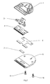
- FIG. 4 to be taken fourth embodiment of a cutting set is identical to the in FIG. 3 shown cutting set except for the fact that here a guide plate 6 is provided, which is not fixed by screws, so that an adjustment of the cutting length can be done by operating a Vorstellhebels 2.
- the number of magnets is by no means limited to two.
- FIG. 5 shows a fifth embodiment of a cutting set, whose general structure with the in FIG. 1 matches the cutting set shown.
- a threaded adjusting element 11 is additionally provided, by means of which the distance between the magnet 5 and the shearing comb 8 can be varied. Since this distance affects the strength of the acting magnetic force sensitive, this is variably adjustable in a cutting set this embodiment.
- the geometry and connection dimensions of the cutting set, in particular of the cutting set carrier 8 may preferably be designed so that the cutting set according to the invention can be placed on conventional electric hair cutting machines, whereby a simple conversion is possible.
Landscapes
- Life Sciences & Earth Sciences (AREA)
- Forests & Forestry (AREA)
- Engineering & Computer Science (AREA)
- Mechanical Engineering (AREA)
- Dry Shavers And Clippers (AREA)
Abstract
Description
Die Erfindung betrifft einen Schneidsatz für eine elektrische Haarschneidemaschine gemäß Patentanspruch 1 sowie eine elektrische Haarschneidemaschine gemäß Patentanspruch 7.The invention relates to a cutting set for an electric hair clipper according to
Allgemein bekannt ist die Verwendung von Schneidsätzen für Haarschneidemaschinen. Bekannte Schneidsätze für elektrische Haarschneidemaschinen, wie sie etwa die
Kritisch für die Effektivität solcher Schneidsätze ist es, dass Scherkamm und Schermesser mit einer definierten Andruckkraft, dem sogenannten Schneiddruck, eng aneinander geführt werden. Herrscht ein zu geringer Schneiddruck, d. h. eine zu geringe Andruckkraft, verschlechtert sich das Schneidverhalten, im Extremfall kann das zu schneidende Haar in den sich ausbildenden Zwischenraum beim Abheben des Schermessers vom Scherkamm hineingezogen werden, was den Abschneideprozess behindert und zu einem schmerzhaften Festklemmen einzelner Haare führen kann.Critical to the effectiveness of such cutting sets is that Scherkamm and shearing blades with a defined pressure, the so-called cutting pressure, are guided close to each other. If the cutting pressure is too low, d. H. Too little pressure force, the cutting behavior deteriorates, in extreme cases, the hair to be cut can be drawn into the forming gap when lifting the doctor from the cutting comb, which hinders the cutting process and can lead to a painful clamping individual hair.
Daher ist es üblich, eine Andruckvorrichtung vorzusehen, die sicherstellt, dass Scherkamm und Schermesser gegeneinander mit der erforderlichen Andruckkraft geführt werden. Andruckvorrichtungen in Form von Federarmen sind beispielsweise aus der
Allerdings wird ein optimales Schnittergebnis genau dann erreicht, wenn Scherkamm und Schermesser exakt parallel zur vorgesehenen Schnittkante geführt werden.However, an optimal cutting result is achieved exactly when the cutting comb and the shearing blades are guided exactly parallel to the intended cutting edge.
Einer solchen ideal linearen Bewegung stehen die bekannten, vorstehend beschriebenen Andruckvorrichtungen jedoch insofern entgegen, als sie in der Regel Zwangsbedingungen für die relative Bewegung von Scherkamm und Schermesser zueinander darstellen, da sie mindestens eine mechanische Verbindung zwischen einem festen und einem bewegten Bauteil darstellen, die nicht in alle Richtungen frei beweglich ist. So werden die das Schermesser führenden Federarme beim Durchlaufen der Oszillationsbewegung seitlich ausgelenkt, so dass das Schermesser keine ideale lineare Querbewegung relativ zum Scherkamm erfährt. Die sich ergebende kreisbogensegmentförmige Bewegung ist für ein optimales Schneidergebnis nachteilig.However, such an ideally linear movement is precluded by the prior art pressure devices described above in that they are generally constraints on the relative movement of the shear comb and shear blades relative to one another since they provide at least one mechanical connection between a fixed and a moving component is freely movable in all directions. Thus, the shear blades leading spring arms are deflected laterally when passing through the oscillatory motion, so that the shearing blade experiences no ideal linear transverse movement relative to the shearing comb. The resulting circular arc segment-shaped movement is disadvantageous for an optimal cutting result.
Die vorangemeldete, jedoch nachveröffentlichte
Ziel der Erfindung ist daher die Bereitstellung eines Schneidsatzes für eine elektrische Haarschneidemaschine bzw. eine Haarschneidemaschine, der bzw. die eine optimale Führung der Bewegung von Schermesser und Scherkamm bei gleichzeitiger Bereitstellung des notwendigen Schneiddruckes gewährleistet.The aim of the invention is therefore to provide a cutting set for an electric hair clipper or a hair clipper, which ensures optimal management of the movement of the shear blade and shearing comb while providing the necessary cutting pressure.
Dieses Ziel wird erfindungsgemäß erreicht durch einen Schneidsatz für eine elektrische Haarschneidemaschine mit den Merkmalen des Patentanspruchs 1 sowie durch eine Haarschneidemaschine mit den Merkmalen des Patentanspruchs 7.This object is achieved by a cutting set for an electric hair clipper with the features of
Der Erfindung liegt die Erkenntnis zu Grunde, dass eine elegante und effiziente Möglichkeit zur Bereitstellung des Andrucks zwischen Scherkamm und Schermesser darin besteht, mindestens einen Magneten so zwischen diesen beiden Bauteilen anzuordnen, dass der notwendige Schneiddruck bereitgestellt wird, während gleichzeitig ein zwischen Schermesser und Scherkamm angeordnetes Führungsblech eine ideal lineare Relativbewegung von Scherkamm und Schermesser ermöglicht.The invention is based on the finding that an elegant and efficient way to provide the contact pressure between the cutting comb and the doctor blade is to arrange at least one magnet between these two components so that the necessary cutting pressure is provided, while at the same time an interposed between the shear blade and shearing comb Guide plate allows an ideal linear relative movement of shearing comb and shearing blades.
Der erfindungsgemäße Schneidsatz für elektrische Haarschneidemaschinen weist somit einen Scherkamm und ein auf dem Scherkamm aufliegendes Schermesser, welche über einen antriebsseitig befestigten Mitnehmer relativ zueinander oszillierend bewegbar sind, auf, wobei zusätzlich mindestens ein Magnet im Bereich des Schermessers und/oder des Scherkamms angeordnet ist. Dabei ist der Magnet nicht das einzige zwischen diesen beiden Bauteilen angeordnete Element; vielmehr ist dort das Führungsblech zur Führung des Schermessers zwischen besagten Bauteilen vorgesehen.The cutting set according to the invention for electric hair clipping machines thus has a shearing comb and a shearing ridge resting on the shearing ridge, which are oscillatingly movable relative to each other via a driver mounted on the drive side, wherein additionally at least one magnet in the region of the shearing blade and / or the shearing comb is arranged. In this case, the magnet is not the only element arranged between these two components; rather, there is that Guide plate provided for guiding the shearing blade between said components.
Der mindestens eine Magnet kann an unterschiedlichen Stellen des Schneidsatzes angeordnet sein. Es ist beispielsweise möglich, einen Magneten in der Schermesser/Mitnehmereinheit zu montieren, so dass die Magnetkraft zwischen Magnet und Scherkamm den Schneiddruck erzeugt.The at least one magnet can be arranged at different locations of the cutting set. For example, it is possible to mount a magnet in the shearing blade / driver unit so that the magnetic force between the magnet and the shearing comb generates the cutting pressure.
Alternativ kann ein Magnet am Schneidkamm angeordnet sein, wofür in vorteilhafter Ausgestaltung eine Vertiefung im Schneidkamm ausgeformt ist, in welche der Magnet passt. In diesem Fall erzeugt die Magnetkraft zwischen Magnet und Schermesser den Schneiddruck.Alternatively, a magnet may be arranged on the cutting comb, for which, in an advantageous embodiment, a depression is formed in the cutting comb into which the magnet fits. In this case, the magnetic force between the magnet and the blade produces the cutting pressure.
Schließlich ist es auch noch denkbar, jeweils mindestens einen Magneten in der Schermesser/Mitnehmereinheit und im Scherkamm zu montieren. In diesem Fall wird der Schneiddruck durch die Magnetkraft zwischen den beiden Magneten bereitgestellt. Diese Anordnung ermöglicht es, besonders hohe Schneiddrücke zu erzielen. Allgemein ist der Schneiddruck durch Auswahl des Magneten beeinflussbar.Finally, it is also conceivable to mount in each case at least one magnet in the shearing blade / driver unit and in the shearing comb. In this case, the cutting pressure is provided by the magnetic force between the two magnets. This arrangement makes it possible to achieve very high cutting pressures. In general, the cutting pressure can be influenced by selecting the magnet.
In einer besonders bevorzugten Ausführungsform ist weiter ein Verstellelement mit einem Gewinde vorgesehen, mit dessen Hilfe der Abstand zwischen Magnet und Scherkamm, damit also die Magnetkraft zwischen diesen beiden Bauteilen und demnach der Schneiddruck variiert werden kann.In a particularly preferred embodiment, an adjusting element is further provided with a thread, by means of which the distance between the magnet and shearing comb, so that thus the magnetic force between these two components and therefore the cutting pressure can be varied.
Vorzugsweise ist das Führungsblech für das Schermesser verschiebbar ausgeführt, wodurch eine Schnittlängenverstellung ermöglicht wird.Preferably, the guide plate is designed to be displaceable for the shearing blade, whereby a cutting length adjustment is made possible.
Die Erfindung wird anhand der folgenden speziellen Ausführungsbeispiele ausführlich erläutert.The invention will be explained in detail with reference to the following specific embodiments.
Es zeigt:
Figur 1- eine Explosionszeichnung eines erfindungsgemäßen Schneidsatzes mit fixiertem Führungsblech mit in der Schermesser/Mitnehmereinheit montiertem Magneten,
Figur 2- eine Explosionszeichnung eines erfindungsgemäßen Schneidsatzes mit fixiertem Führungsblech mit im Scherkamm montiertem Magneten,
Figur 3- eine Explosionszeichnung eines erfindungsgemäßen Schneidsatzes mit fixiertem Führungsblech mit einem in der Schermesser/Mitnehmereinheit montiertem Magneten und einem im Scherkamm montierten Magneten,
Figur 4- eine Explosionszeichnung eines erfindungsgemäßen Schneidsatzes mit beweglich montiertem Führungsblech mit einem in der Schermesser/Mitnehmereinheit montiertem Magneten und einem im Scherkamm montierten Magneten,
Figur 5- eine Explosionszeichnung eines erfindungsgemäßen Schneidsatzes mit fixiertem Führungsblech mit einem in der Schermesser/Mitnehmereinheit montiertem Magneten, dessen Abstand zum Scherkamm mittels eines Verstellelements einstellbar ist.
- FIG. 1
- an exploded view of a cutting set according to the invention with fixed guide plate with mounted in the shear blade / driver unit magnet,
- FIG. 2
- an exploded view of a cutting set according to the invention with a fixed guide plate with magnets mounted in the shear comb,
- FIG. 3
- an exploded view of a cutting set according to the invention with a fixed guide plate with a mounted in the blade / driver unit magnet and a mounted in the shear comb magnet,
- FIG. 4
- an exploded view of a cutting set according to the invention with movably mounted guide plate with a mounted in the blade / driver unit magnet and a mounted in the shear comb magnet,
- FIG. 5
- an exploded view of a cutting set according to the invention with fixed guide plate with a mounted in the shear blade / driver unit magnet whose distance from the shearing comb by means of an adjusting element is adjustable.
Das der
Bei den Ausführungsformen mit zwei Magneten, deren Wechselwirkung den Schneiddruck bereitstellt, lassen sich höhere Schneiddrücke erreichen. Prinzipiell ist die Zahl der Magneten auch keineswegs auf zwei limitiert.In the embodiments with two magnets whose interaction provides the cutting pressure, higher cutting pressures can be achieved. In principle, the number of magnets is by no means limited to two.
In allen Fällen können Geometrie und Anschlussmaße des Schneidsatzes, insbesondere des Schneidsatzträgers 8 vorzugsweise so gestaltet sein, dass der erfindungsgemäße Schneidsatz auf herkömmliche elektrische Haarschneidemaschinen aufgesetzt werden kann, wodurch eine problemlose Umrüstung möglich ist.In all cases, the geometry and connection dimensions of the cutting set, in particular of the cutting set
- 11
- SchneidsatzträgerCutting set carrier
- 22
- Verstellhebeladjusting
- 33
- Mitnehmertakeaway
- 44
- Schermesserrazor
- 55
- Magnetmagnet
- 66
- Führungsblechguide plate
- 77
- Magnetmagnet
- 88th
- Scherkammtrimmer
- 99
- Schraubescrew
- 1010
- Schraubescrew
- 1111
- Verstellelement mit GewindeAdjustment element with thread
Claims (7)
dadurch gekennzeichnet, dass der mindestens eine Magnet (5) im Bereich des Schermessers (4) angeordnet ist.Cutting set according to claim 1,
characterized in that the at least one magnet (5) is arranged in the region of the shearing blade (4).
dadurch gekennzeichnet, dass der mindestens eine Magnet (7) im Bereich des Scherkamms (8) angeordnet ist.Cutting set according to claim 1,
characterized in that the at least one magnet (7) is arranged in the region of the shearing comb (8).
dadurch gekennzeichnet, dass mindestens ein Magnet (5) im Bereich des Schermessers (4) angeordnet ist und mindestens ein weiterer Magnet (7) im Bereich des Scherkamms (8) angeordnet ist.Cutting set according to claim 1,
characterized in that at least one magnet (5) in the region of the shear blade (4) is arranged and at least one further magnet (7) in the region of the shearing comb (8) is arranged.
dadurch gekennzeichnet, dass zum Variieren der Andruckkraft der Abstand zwischen Magnet (5) und Scherkamm (8) einstellbar ist.Cutting set according to claim 1,
characterized in that for varying the pressing force, the distance between the magnet (5) and shearing comb (8) is adjustable.
dadurch gekennzeichnet, dass das zwischen Scherkamm (8) und Schermesser (4) angeordnete Führungsblech (6) verschiebbar ist.Cutting set according to one of claims 1 to 5,
characterized in that between the shear comb (8) and shearing blade (4) arranged guide plate (6) is displaceable.
Applications Claiming Priority (1)
| Application Number | Priority Date | Filing Date | Title |
|---|---|---|---|
| DE200710015805 DE102007015805B4 (en) | 2007-03-30 | 2007-03-30 | Cutting set for electric hair clippers |
Publications (1)
| Publication Number | Publication Date |
|---|---|
| EP1974875A1 true EP1974875A1 (en) | 2008-10-01 |
Family
ID=39535299
Family Applications (1)
| Application Number | Title | Priority Date | Filing Date |
|---|---|---|---|
| EP08005935A Withdrawn EP1974875A1 (en) | 2007-03-30 | 2008-03-28 | Cutting unit for an electric hair cutting machine and electric hair cutting machine |
Country Status (2)
| Country | Link |
|---|---|
| EP (1) | EP1974875A1 (en) |
| DE (1) | DE102007015805B4 (en) |
Cited By (6)
| Publication number | Priority date | Publication date | Assignee | Title |
|---|---|---|---|---|
| CN103112018A (en) * | 2013-03-15 | 2013-05-22 | 珠海新秀丽家居用品有限公司 | Inner arc-shaped haircut cutting head combination |
| CN103144122A (en) * | 2013-03-12 | 2013-06-12 | 宁波邦首电器有限公司 | Knife head with knife pressing frame to control knife teeth |
| US20170246751A1 (en) * | 2014-09-18 | 2017-08-31 | Koninklijke Philips N.V. | Blade set, cutting appliance, and related manufacturing method |
| WO2020037124A1 (en) | 2018-08-17 | 2020-02-20 | Andis Company | Adjustable blade assembly having magnetic tensioning |
| US20230219246A1 (en) * | 2022-01-11 | 2023-07-13 | Ningbo Jibeibei Technology Co., Ltd. | Magnetic suspension shaver head structure |
| WO2024072791A1 (en) * | 2022-09-29 | 2024-04-04 | Andis Company | Adjustable blade assembly having magnetic tensioning |
Families Citing this family (2)
| Publication number | Priority date | Publication date | Assignee | Title |
|---|---|---|---|---|
| DE102009015276B4 (en) * | 2009-04-01 | 2015-10-15 | Wahl Gmbh | Hair clipper with interchangeable cutting set and cutting length adjustment device |
| CN104128936B (en) * | 2014-07-09 | 2016-10-05 | 浙江百特电器有限公司 | A kind of magnetic-type bit mechanism and apply the hair scissors of this mechanism |
Citations (5)
| Publication number | Priority date | Publication date | Assignee | Title |
|---|---|---|---|---|
| US4581833A (en) | 1985-01-31 | 1986-04-15 | Louie Zeravica | Offset shovel assembly for use with backhoe |
| WO1998047673A1 (en) | 1997-04-24 | 1998-10-29 | Koninklijke Philips Electronics N.V. | Hair-cutting apparatus having a toothed cutting device, and toothed cutting device for a hair-cutting apparatus |
| DE10355154A1 (en) | 2003-11-26 | 2005-06-30 | Wahl Gmbh | Cutting set for electric hair clippers |
| WO2005075160A1 (en) * | 2004-02-09 | 2005-08-18 | Tae-Jun Oh | Haircutting blade with oilless metal piece |
| WO2007125491A1 (en) | 2006-05-01 | 2007-11-08 | Koninklijke Philips Electronics N.V. | Cutting device and hair-cutting apparatus |
Family Cites Families (3)
| Publication number | Priority date | Publication date | Assignee | Title |
|---|---|---|---|---|
| CH311329A (en) * | 1953-04-21 | 1955-11-30 | Waeger Emil | Safety razor. |
| US3740841A (en) * | 1970-04-20 | 1973-06-26 | Philip Morris Inc | Safety razor embodying blade pressure control |
| US4581822A (en) | 1983-12-15 | 1986-04-15 | Kyushu Hitachi Maxell, Ltd. | Electric hair clipper |
-
2007
- 2007-03-30 DE DE200710015805 patent/DE102007015805B4/en active Active
-
2008
- 2008-03-28 EP EP08005935A patent/EP1974875A1/en not_active Withdrawn
Patent Citations (5)
| Publication number | Priority date | Publication date | Assignee | Title |
|---|---|---|---|---|
| US4581833A (en) | 1985-01-31 | 1986-04-15 | Louie Zeravica | Offset shovel assembly for use with backhoe |
| WO1998047673A1 (en) | 1997-04-24 | 1998-10-29 | Koninklijke Philips Electronics N.V. | Hair-cutting apparatus having a toothed cutting device, and toothed cutting device for a hair-cutting apparatus |
| DE10355154A1 (en) | 2003-11-26 | 2005-06-30 | Wahl Gmbh | Cutting set for electric hair clippers |
| WO2005075160A1 (en) * | 2004-02-09 | 2005-08-18 | Tae-Jun Oh | Haircutting blade with oilless metal piece |
| WO2007125491A1 (en) | 2006-05-01 | 2007-11-08 | Koninklijke Philips Electronics N.V. | Cutting device and hair-cutting apparatus |
Cited By (11)
| Publication number | Priority date | Publication date | Assignee | Title |
|---|---|---|---|---|
| CN103144122A (en) * | 2013-03-12 | 2013-06-12 | 宁波邦首电器有限公司 | Knife head with knife pressing frame to control knife teeth |
| CN103112018A (en) * | 2013-03-15 | 2013-05-22 | 珠海新秀丽家居用品有限公司 | Inner arc-shaped haircut cutting head combination |
| US20170246751A1 (en) * | 2014-09-18 | 2017-08-31 | Koninklijke Philips N.V. | Blade set, cutting appliance, and related manufacturing method |
| US10406702B2 (en) * | 2014-09-18 | 2019-09-10 | Koninkliike Philips N.V. | Blade set, cutting appliance, and related manufacturing method |
| WO2020037124A1 (en) | 2018-08-17 | 2020-02-20 | Andis Company | Adjustable blade assembly having magnetic tensioning |
| CN112566762A (en) * | 2018-08-17 | 2021-03-26 | 安迪思公司 | Adjustable blade assembly with magnetic tension |
| JP2021533871A (en) * | 2018-08-17 | 2021-12-09 | アンディス・カンパニーAndis Company | Adjustable blade assembly with magnetic tension |
| EP3837097A4 (en) * | 2018-08-17 | 2022-07-20 | Andis Company | Adjustable blade assembly having magnetic tensioning |
| US11504864B2 (en) * | 2018-08-17 | 2022-11-22 | Andis Company | Adjustable blade assembly having magnetic tensioning |
| US20230219246A1 (en) * | 2022-01-11 | 2023-07-13 | Ningbo Jibeibei Technology Co., Ltd. | Magnetic suspension shaver head structure |
| WO2024072791A1 (en) * | 2022-09-29 | 2024-04-04 | Andis Company | Adjustable blade assembly having magnetic tensioning |
Also Published As
| Publication number | Publication date |
|---|---|
| DE102007015805A1 (en) | 2008-10-02 |
| DE102007015805B4 (en) | 2008-11-13 |
Similar Documents
| Publication | Publication Date | Title |
|---|---|---|
| EP1974875A1 (en) | Cutting unit for an electric hair cutting machine and electric hair cutting machine | |
| EP0963280B1 (en) | Hair clipping machine with device for adjusting length of cut | |
| EP2004364B1 (en) | Electric shaver with pivotable shearing head | |
| EP1667822B1 (en) | Trimming system for an electrical hair removal appliance | |
| DE69224761T2 (en) | Dry shaver | |
| EP0861141B1 (en) | Dry shaver | |
| EP1694475B1 (en) | Cutting head for an electric hair cutting machine | |
| DE69703844T2 (en) | DRY SHAVER | |
| DE102013204026B4 (en) | Actuator arrangement for an ultrasonic motor | |
| DE2241384A1 (en) | ELECTRIC DRY SHAVER | |
| DE1553804B2 (en) | ELECTRIC DRY SHAVER | |
| EP0600998B1 (en) | Depilatory device | |
| DE1162462B (en) | A device driven by a vibration motor, especially a dry shaver | |
| DE102018209410A1 (en) | power tool | |
| DE2429539B2 (en) | DRIVE ARRANGEMENT FOR AN ELECTRIC DRY SHAVER | |
| DE69504163T2 (en) | SHAVER | |
| DE69936127T2 (en) | saw blade clamp | |
| EP0856386B1 (en) | Electric hair cutting machine | |
| DE2719556A1 (en) | ELECTRIC SHAVER | |
| DE10227509A1 (en) | piezoMotor | |
| WO2003090338A2 (en) | Piezo motor | |
| DE29724477U1 (en) | Hair clipper with cutting length adjustment device | |
| DE102008010444B4 (en) | Cutting set for a hair clipper | |
| DE1553790C3 (en) | Shaving head for dry razors | |
| DE2236297A1 (en) | DRY SHAVER |
Legal Events
| Date | Code | Title | Description |
|---|---|---|---|
| PUAI | Public reference made under article 153(3) epc to a published international application that has entered the european phase |
Free format text: ORIGINAL CODE: 0009012 |
|
| AK | Designated contracting states |
Kind code of ref document: A1 Designated state(s): AT BE BG CH CY CZ DE DK EE ES FI FR GB GR HR HU IE IS IT LI LT LU LV MC MT NL NO PL PT RO SE SI SK TR |
|
| AX | Request for extension of the european patent |
Extension state: AL BA MK RS |
|
| AKX | Designation fees paid | ||
| STAA | Information on the status of an ep patent application or granted ep patent |
Free format text: STATUS: THE APPLICATION IS DEEMED TO BE WITHDRAWN |
|
| 18D | Application deemed to be withdrawn |
Effective date: 20090402 |
|
| REG | Reference to a national code |
Ref country code: DE Ref legal event code: 8566 |