EP2004364B1 - Electric shaver with pivotable shearing head - Google Patents
Electric shaver with pivotable shearing head Download PDFInfo
- Publication number
- EP2004364B1 EP2004364B1 EP07711726A EP07711726A EP2004364B1 EP 2004364 B1 EP2004364 B1 EP 2004364B1 EP 07711726 A EP07711726 A EP 07711726A EP 07711726 A EP07711726 A EP 07711726A EP 2004364 B1 EP2004364 B1 EP 2004364B1
- Authority
- EP
- European Patent Office
- Prior art keywords
- elements
- shaving head
- dry shaver
- shaver according
- drive
- Prior art date
- Legal status (The legal status is an assumption and is not a legal conclusion. Google has not performed a legal analysis and makes no representation as to the accuracy of the status listed.)
- Revoked
Links
Images


Classifications
-
- B—PERFORMING OPERATIONS; TRANSPORTING
- B26—HAND CUTTING TOOLS; CUTTING; SEVERING
- B26B—HAND-HELD CUTTING TOOLS NOT OTHERWISE PROVIDED FOR
- B26B19/00—Clippers or shavers operating with a plurality of cutting edges, e.g. hair clippers, dry shavers
- B26B19/02—Clippers or shavers operating with a plurality of cutting edges, e.g. hair clippers, dry shavers of the reciprocating-cutter type
- B26B19/04—Cutting heads therefor; Cutters therefor; Securing equipment thereof
- B26B19/048—Complete cutting head being movable
-
- B—PERFORMING OPERATIONS; TRANSPORTING
- B26—HAND CUTTING TOOLS; CUTTING; SEVERING
- B26B—HAND-HELD CUTTING TOOLS NOT OTHERWISE PROVIDED FOR
- B26B19/00—Clippers or shavers operating with a plurality of cutting edges, e.g. hair clippers, dry shavers
- B26B19/28—Drive layout for hair clippers or dry shavers, e.g. providing for electromotive drive
- B26B19/288—Balance by opposing oscillation
Definitions
- the invention relates to a dry shaver according to the preamble of patent claim 1.
- Such a razor is from the US 2003/0221319 A1 known. This has oscillating elements with coupling portions which are straight, so that during a pivoting of the shaving head relative to the housing an undesirable elevational displacement of the coupling sections takes place relative to the drive elements.
- the shaving head is pivotally mounted about two axes relative to the housing.
- Another dry shaver is from the DE 36 10 736 C2 known.
- the dry shaving apparatus disclosed there although already characterized by very good adaptability to the shaving contour of the skin and thus provides superior shaving results.
- the known razor has a projecting from the housing oscillating driven drive pin which drives a drive plate which is arranged on the pivotable shaving head, wherein on the drive plate two lower blades are arranged, then soft together and in the same direction back and forth with the drive motor. Without suitable countermeasures, the same oscillating bottom blades would create disturbing vibrations for the user.
- Corresponding vibration reduction measures for example by counterbalancing weights, are complex and require additional space in the pivotable shaving head, wherein the weight of the shaving head is additionally increased. Such additional measures are therefore unfavorable in terms of the compactness of the shaving head, complicate the balance and the dynamics in the adaptation to the respective skin contour and thus reduce the shaving performance and comfort.
- the object of the present invention is to improve the known dry shaver; In particular, care should be taken with the least possible effort to ensure that no disturbing vibrations occur during operation. This should nevertheless allow a compact design of the dry shaver; In particular, the shaving head should be feasible in low height.
- the vibration behavior of a dry shaver with a pivotable shaving head can be extremely improved in a surprisingly simple manner or it can already compensate for vibrations directly in the shaving head itself.
- An embodiment of the invention provides that at least two translationally driven oscillating drive elements are present, which are each coupled to one of a plurality of vibrating elements. As a result, the space required for the arrangement of swing bridges in the shaving head itself can be extremely minimized.
- the oscillating elements are provided with coupling sections. These coupling sections are according to the invention concentric to the pivot axis. As a result, the coupling sections are moved during the pivoting about the axis exclusively on a respective associated radius. The axial distances of the eccentric sections from each other can therefore be chosen very small.
- the coupling sections can be designed to lie close to each other.
- the eccentric portions must therefore have only a small axial extent, since, in contrast to straight-line design of the coupling sections no tilting of the coupling elements relative to the drive shaft in dependence on the pivot angle occurs about the axis.
- An embodiment of the invention in which only a rotationally driven drive element must be led out of the housing, provides that the drive motor has a rotationally driven drive shaft, which has at least two in the axial direction one behind the other arranged eccentric portions. Furthermore, it is conducive to a simple construction, when the drive elements engage directly in sections of the oscillating elements. Depending on the requirements or restrictions with regard to the available installation space, it can be advantageous if the drive elements are each connected to the oscillation elements by means of intermediate transmission means. This transfer means can be designed, for example, as a connecting rod or else as a joint push rod.
- each of the oscillating elements has a section provided with a slot for direct or indirect coupling of the respective drive element, the slot extending transversely to the pivot axis of the shaving head.
- at least one of the slots is formed as a passage slot, so that according to a particularly simple embodiment of the invention, the drive elements can be designed as two consecutively arranged eccentric.
- a shaving head with two different sized shear systems provides an embodiment of the invention in which the oscillating elements are driven with different sized amplitudes. If, for example, the lower blades of the respective shearing systems have masses of different sizes, unwanted vibrations result from this. By correspondingly tuned vibration amplitudes of different sizes, these can be compensated.
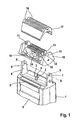
- Fig. 1 shows a dry shaver with a housing 1, which has in the region of the upper end face a recess 2 through which a first and a second eccentric portion 3 and 4 of a drive shaft protrudes.
- This drive shaft is driven in rotation by a not visible in this illustration electric motor.
- a trimmer 5 is arranged, which is displaceable and switchable via a switch 6.
- the upper end face also has two arms 7 and 8 designed as an extension of the narrow housing sides, which have bearing points 9 for receiving the shaving head 10.
- the shaving head 10 has corresponding bearings 11, which are arranged on the side cheeks. In the assembled state of the shaving head 10 is then mounted in the housing 1 such that it is pivotable about the axis X-X.
- This pivoting ensures that the two shear systems of the shaving head 10 to be described later always rest optimally on the skin to be shaved, regardless of the angular position of the housing 1 relative to the skin.
- a first and a second lower blade 12 and 13 by means of associated swing bridges, namely the first swing bridge 14 and the second swing bridge 15, translationally parallel to the pivot axis X-X slidably mounted.
- Each lower blade 12, 13 has a plurality of successively lined up and parallel aligned blades.
- each lower blade 12, 13 is associated with a shaving foil 16, which is provided in a removable frame 17.
- the latter has on its inside corresponding recesses, by means of which the removable frame 17 can be coupled in conjunction with arranged on the shaving head 10 locking bars 18 fixed to the shaving head 10.
- the shear sheets 16 are curved, include the rounded blades of the lower blades 12, 13 partially and have a plurality of holes for the entry of the hair to be shaved. In conjunction with the oscillating reciprocating motion of the lower blades 12, 13, the hairs passing through the holes are then sheared between the shear foil and the corresponding blade of the lower blade.
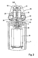
- Fig. 2 shows a central section perpendicular to the axis XX through a dry shaver according to the invention.
- the electric motor 19 is firmly integrated in the housing 1 and can be actuated by an on / off switch, not shown.
- On the drive shaft 20 is secured against rotation and axially secured against displacement, a molded part, which has a first and a second eccentric portion 3 and 4 respectively.
- these eccentric portions are arranged axially one behind the other and their eccentricities are diametrically opposite, so are rotated by 180 ° from each other.
- the first eccentric portion 3 is closer to the electric motor 19, while the second eccentric portion facing the shaving head 10.
- the first eccentric portion 3 engages in the coupling portion 21, which is integrally formed on the first swing bridge 14 and thus connects the first lower blade 12 with the electric motor 19.
- a coupling portion 22 is also formed, which is in communication with the second eccentric portion 4 and thus with the electric motor 19.
- the eccentricities of the two eccentric portions 3 and 4 are about 1.5 mm, so that when operating the electric motor 19, the lower blade 12, 13 perform a mutually opposite vibration with the amplitude of about 3 mm. Since the eccentric portions are arranged on the same drive shaft 20, the vibrations of the lower blades 12, 13 also have the same vibration frequency. As long as the moving masses are the same size, vibrations are completely compensated by the opposing motion. Of course, it is also possible to build a shaving head, which has shear systems of different sizes, which then leads to different sized moving masses. In order to achieve a complete compensation of the vibration forces in this case, it is possible to tune the drive system so that the eccentricities of the eccentric portions differ from each other. This would impose a lower amplitude on the larger mass shear system than the lighter shear system.
- the coupling portion 21 has to receive the eccentric portion 3 a transverse to the pivot axis XX slot 23, while the coupling portion 22 has an equally extending slot 24 in which the second eccentric portion 4 is received.
- the length of the slots 23 and 24 is matched to the maximum pivot angle of the shaving head 10. In the vertical direction, the slots 23 and 24 are made continuous; at least the slot 23 must be continuous, so that the second eccentric portion 3 can be passed through it.
- the slot 24 may also be formed as a non-continuous slot-shaped groove.
- Both swing bridges 14, 15 each carry a receiving pot 25 and 26, respectively, in which the lower blades 12 and 13 can be mounted in a conventional manner by means of corresponding axes or pins. Between the receiving pots 25, 26 and their associated lower blades 12 and 13 are each spring elements arranged biasing the lower blade in the direction of the shear sheets 16. In this way, a flat concern of the lower blade on the associated shaving foil is always ensured.
- the Fig. 3 shows a swing bridge assembly according to Fig. 2
- the two coupling sections 21 and 22 are interleaved and each cover at least perpendicular to the direction of oscillation (double arrow) the area below both swing bridges.
- Fig. 4 shows an embodiment of the invention in which the coupling portions 21, 22 of the swing bridges 14, 15 are not interleaved, but are arranged side by side. Also in this example, an electric motor 19 is arranged with a drive shaft 20 in the housing 1 of the shaver, wherein on the drive shaft 20, two eccentric portions 3 and 4 are arranged. On each of the eccentric portions 3, 4, a connecting rod 32 and 33 is mounted, the pins 34 and 35 with associated coupling portions 21 and 22 of the swing bridges 14 and 15 is in communication.
- the pins 34 and 35 are slidably mounted in groove-shaped slots 23 and 24, wherein, as in the preceding figures, these slots 23 and 24 in the associated coupling portions 21 and 22 extend transversely to the pivot axis XX of the shaving head 10.
- the oscillating bridges 14 and 15 lie one behind the other in the drawing plane and each carry one of the lower blades 12 and 13.
- the oscillating linear oscillation is transmitted to the swing bridges parallel to the pivot axis XX via the connecting rods 32, 33. Since - as in the previous example - the eccentric sections 3, 4 by 180 ° against each other are twisted, the swinging movement, the swing bridges 14, 15 in opposite directions to each other. Due to the course of the slots 23, 24 transversely to the pivot axis XX and the displaceable receiving the pins 34, 35 in them, the shaving head 10 can be pivoted while maintaining the driving connection between the electric motor 19 and swing bridges 14, 15.
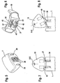
- FIGS. 5 to 8 show an embodiment which does not fall under the scope of the claims, in which two opposite to each other oscillating moving drive elements protrude from the housing 1.
- These drive elements are two pin-shaped oscillators 36 which are guided out of the housing in a sealed manner and have recesses for the articulated reception of the lower end 38, each of which has a joint push rod 37.
- the storage of the joint push rods in the oscillators is both pivotable, as well as linearly displaceable.
- FIGS. 5 and 6 the housing of the dry shaver and the shaving head 10 is shown separated from each other, it was dispensed with the representation of a retaining fork for pivotally receiving the shaving head 10.
- This fork is led out of the housing 1 through the openings 39 and contains bearings which cooperate with corresponding bearing points of the shaving head in a conventional manner.
- Fig. 7 shows a side view in which the shaving head 10 is in a central position
- the Fig. 8 the deflected pivot position of the shaving head 10 relative to the housing 1 represents.
- each of the two articulated push rods 37 is articulated via corresponding eyelets 41, each with a swing plate 42.
- This connection allows a pivotability of the joint push rod 37 about an axis parallel to the pivot axis XX extending axis. It also lies parallel to the direction of oscillation of the oscillators or the respectively associated with them vibrating plates 42. Due to this connection, the vibrating plates 42 are driven in opposite directions linearly oscillating. These contain not shown arrangements for receiving the lower blade.
- the pivotability of the articulated push rods within their bearings and the linear displaceability of the lower end 38 within the oscillators 36 is coordinated so that this drive connection can follow the maximum pivoting of the shaving head 10 relative to the housing 1 about the pivot axis XX.
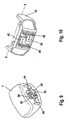
- FIGS. 9 and 10 show the FIGS. 9 and 10 which, like the representation in the FIGS. 5 and 6 on the one hand show a housing 1 with this separated shaving head 10.
- two adjacently located oscillators 36 which are linearly driven in opposite directions to each other in an oscillating manner, protrude out of the housing 1.
- the oscillators 36 have plate-shaped sections 43, which carry pin elements 44 at an inwardly bent region. These pin members 44 are arranged so far inward that they move in oscillating operation of the oscillators 36 on a common line.
- the shaving head 10 is connected via an unillustrated fork member about the axis XX pivotally connected to the housing 1.
- each pin elements 44 engage in an associated transverse groove 45, which is respectively formed on a swing plate 42, and extends transversely to the pivot axis XX.
- the two oscillating plates 42 are mounted parallel to the pivot axis XX displaceable in the shaving head 10 and are parallel to each other.
- Each transverse groove 45 extends arcuately about the pivot axis XX.
- each transverse groove 45 is disposed in a portion of the associated rocking plate 42 which also at least partially overlaps the adjacent rocking plate. These sections are nested in a staircase shape.
- the two swing plates can be supported by appropriate arrangements, such as tongue and groove or dovetail connection slidably.
- the double arrows in the FIGS. 9 and 10 in each case indicate the direction of oscillation of the oscillatory movement of the affected components, wherein the two oscillators 36 and thus also the respective lower blade-carrying vibrating plates 42 are driven in opposite directions to each other.
Abstract
Description
Die Erfindung betrifft einen Trockenrasierer gemäß dem Oberbegriff des Patentanspruchs 1.The invention relates to a dry shaver according to the preamble of
Ein derartiger Rasierapparat ist aus der
Aus der
Ein weiterer Trockenrasierer ist aus der
Aufgabe der vorliegenden Erfindung ist es, den bekannten Trockenrasierer zu verbessern; insbesondere soll mit geringstmöglichem Aufwand dafür gesorgt werden, daß keine störenden Vibrationen während des Betriebes entstehen. Dies soll dennoch eine kompakte Bauweise des Trockenrasierers ermöglichen; insbesondere soll der Scherkopf in geringer Bauhöhe realisierbar sein.The object of the present invention is to improve the known dry shaver; In particular, care should be taken with the least possible effort to ensure that no disturbing vibrations occur during operation. This should nevertheless allow a compact design of the dry shaver; In particular, the shaving head should be feasible in low height.
Diese Aufgabe wird durch die kennzeichnenden Merkmale des Patentanspruchs 1 gelöst.This object is solved by the characterizing features of
Durch die erfindungsgemäße Lösung kann auf überraschend einfache Weise das Vibrationsverhalten eines Trockenrasierers mit schwenkbarem Scherkopf extrem verbessert werden bzw. es lassen sich Vibrationen bereits unmittelbar im Scherkopf selbst kompensieren. Eine Ausführungsform der Erfindung sieht vor, daß mindestens zwei translatorisch oszillierend angetriebene Antriebselemente vorhanden sind, die jeweils mit einem von mehreren Schwingelementen koppelbar sind. Hierdurch läßt sich der im Scherkopf selbst benötigte Bauraum für die Anordnung von Schwingbrücken extrem minimieren. Die Schwingelemente sind mit Koppelabschnitten versehen. Diese Koppelabschnitte verlaufen erfindungsgemäß konzentrisch zur Schwenkachse. Dadurch werden die Koppelabschnitte während der Verschwenkung um die Achse ausschließlich auf jeweils einem zugeordneten Radius bewegt. Die axialen Abstände der exzentrischen Abschnitte voneinander können daher sehr gering gewählt werden. Ebenso können auch die Koppelabschnitte eng beieinander liegend ausgeführt sein. Auch die exzentrischen Abschnitte müssen deswegen nur eine geringe axiale Erstreckung aufweisen, da im Gegensatz zu im Querschnitt geradliniger Ausbildung der Koppelabschnitte kein Verkippen der Koppelelemente relativ zur Antriebswelle in Abhängigkeit vom Schwenkwinkel um die Achse auftritt.By the solution according to the invention, the vibration behavior of a dry shaver with a pivotable shaving head can be extremely improved in a surprisingly simple manner or it can already compensate for vibrations directly in the shaving head itself. An embodiment of the invention provides that at least two translationally driven oscillating drive elements are present, which are each coupled to one of a plurality of vibrating elements. As a result, the space required for the arrangement of swing bridges in the shaving head itself can be extremely minimized. The oscillating elements are provided with coupling sections. These coupling sections are according to the invention concentric to the pivot axis. As a result, the coupling sections are moved during the pivoting about the axis exclusively on a respective associated radius. The axial distances of the eccentric sections from each other can therefore be chosen very small. Likewise, the coupling sections can be designed to lie close to each other. The eccentric portions must therefore have only a small axial extent, since, in contrast to straight-line design of the coupling sections no tilting of the coupling elements relative to the drive shaft in dependence on the pivot angle occurs about the axis.
Eine Ausführungsform der Erfindung, bei welcher nur ein rotierend angetriebenes Antriebselement aus dem Gehäuse herausgeführt werden muß, sieht vor, daß der Antriebsmotor eine rotierend angetriebene Antriebswelle besitzt, die mindestens zwei in axialer Richtung hintereinander angeordnete exzentrische Abschnitte aufweist. Weiterhin ist es einem einfachen Aufbau förderlich, wenn die Antriebselemente unmittelbar in Abschnitte der Schwingelemente eingreifen. In Abhängigkeit von den Erfordernissen oder Restriktionen bezüglich des zur Verfügung stehenden Bauraumes kann es von Vorteil sein, wenn die Antriebselemente jeweils mittels zwischengeschalteter Übertragungsmittel mit den Schwingelementen verbunden sind. Diese Übertragungsmittel können beispielsweise als Pleuel- oder aber auch als Gelenkschubstange ausgeführt sein. Konstruktiv besonders einfach gestaltet sich die Übertragung der Antriebsenergie in den Scherkopf, wenn jedes der Schwingelemente einen mit einem Schlitz versehenen Abschnitt zum direkten oder indirekten Ankuppeln des jeweiligen Antriebselementes aufweist, wobei der Schlitz quer zur Schwenkachse des Scherkopfes verläuft. Vorteilhafterweise ist dabei mindestens einer der Schlitze als Durchgangsschlitz ausgebildet, so daß gemäß einer besonders einfachen Ausführungsform der Erfindung die Antriebselemente als zwei hintereinander angeordnete Exzenter ausgeführt werden können. Eine in Bezug auf die benötigten Bauteile und den damit verbundenen Montageaufwand optimierte Ausführungsform der Erfindung sieht vor, daß zwei Schwingelemente ineinander gelagert sind, so daß keine zusätzlichen Lagermittel verwendet werden müssen.An embodiment of the invention, in which only a rotationally driven drive element must be led out of the housing, provides that the drive motor has a rotationally driven drive shaft, which has at least two in the axial direction one behind the other arranged eccentric portions. Furthermore, it is conducive to a simple construction, when the drive elements engage directly in sections of the oscillating elements. Depending on the requirements or restrictions with regard to the available installation space, it can be advantageous if the drive elements are each connected to the oscillation elements by means of intermediate transmission means. This transfer means can be designed, for example, as a connecting rod or else as a joint push rod. The transmission of the drive energy into the shaving head is structurally particularly simple if each of the oscillating elements has a section provided with a slot for direct or indirect coupling of the respective drive element, the slot extending transversely to the pivot axis of the shaving head. Advantageously, at least one of the slots is formed as a passage slot, so that according to a particularly simple embodiment of the invention, the drive elements can be designed as two consecutively arranged eccentric. An optimized with respect to the required components and the associated assembly costs embodiment of the invention provides that two oscillating elements are mounted one inside the other, so that no additional storage means must be used.
Besonders große konstruktive und gestalterische Freiheit in Bezug auf die gesamte Geometrie und Gestaltung des Scherkopfes - beispielsweise ist ein Scherkopf mit zwei unterschiedlich großen Schersystemen denkbar - bietet eine Ausführungsform der Erfindung, bei welcher die Schwingelemente mit unterschiedlich großen Amplituden angetrieben werden. Weisen beispielsweise die Untermesser der jeweiligen Schersysteme unterschiedlich große Massen auf, so resultieren daraus unerwünschte Vibrationen. Durch entsprechend abgestimmte unterschiedlich große Schwingungsamplituden können diese kompensiert werden.Particularly large constructive and design freedom with respect to the entire geometry and design of the shaving head - for example, a shaving head with two different sized shear systems is conceivable - provides an embodiment of the invention in which the oscillating elements are driven with different sized amplitudes. If, for example, the lower blades of the respective shearing systems have masses of different sizes, unwanted vibrations result from this. By correspondingly tuned vibration amplitudes of different sizes, these can be compensated.
Weitere Ziele, Merkmale, Vorteile und Anwendungsmöglichkeiten der vorliegenden Erfindung ergeben sich aus der nachfolgenden Beschreibung der Ausführungsbeispiele. Dabei bilden alle beschriebenen oder bildlich dargestellten Merkmale für sich oder in beliebiger Kombination den Gegenstand vorliegender Erfindung, auch unabhängig von ihrer Zusammenfassung in den Ansprüchen oder deren Rückbeziehung.Other objects, features, advantages and applications of the present invention will become apparent from the following description of the embodiments. All described or illustrated features alone or in any combination form the subject matter of the present invention, also regardless of their summary in the claims or their dependency.
Es zeigt:
- Fig. 1
- in räumlicher Darstellung den prinzipiellen Aufbau eines Trockenrasierers gemäß der Erfindung,
- Fig. 2
- einen Schnitt parallel zur Hochachse und quer zur Schwenkachse durch einen erfindungsgemäßen Trockenrasierer,
- Fig. 3
- eine erfindungsgemäße Schwingbrückenanordnung in perspektivischer Dar- stellung,
- Fig. 4
- eine weitere Ausführungsform gemäß der Erfindung,
- Fig. 5 bis 8
- in mehreren Darstellungen einen alternative Ausführungsform die nicht unter den Schutzbereich der Ansprüche fällt, und
- Fig. 9 und 10
- eine weitere Ausführungsform der Erfindung.
- Fig. 1
- in a spatial representation of the basic structure of a dry shaver according to the invention,
- Fig. 2
- a section parallel to the vertical axis and transversely to the pivot axis by a dry shaver according to the invention,
- Fig. 3
- an inventive swing bridge arrangement in perspective view,
- Fig. 4
- another embodiment according to the invention,
- Fig. 5 to 8
- in several illustrations an alternative embodiment not falling within the scope of the claims, and
- FIGS. 9 and 10
- a further embodiment of the invention.
Einander entsprechenden Bau- und Funktionsteilen werden im folgenden gleiche Bezugszeichen zugeordnet.Corresponding structural and functional parts are assigned the same reference numerals in the following.
An der vorderen breiten Gehäuseseite ist ein Trimmer 5 angeordnet, welcher über einen Schalter 6 verschiebbar und einschaltbar ist. Die obere Stirnseite verfügt auch über zwei als Verlängerung der schmalen Gehäuseseiten ausgebildete Arme 7 und 8, welche Lagerstellen 9 zur Aufnahme des Scherkopfes 10 aufweisen. Hierzu weist der Scherkopf 10 korrespondierende Lagerungen 11 auf, die an dessen Seitenwangen angeordnet sind. In zusammengebautem Zustand ist der Scherkopf 10 dann im Gehäuse 1 derart gelagert, daß er um die Achse X-X schwenkbar ist.At the front wide side of the housing, a
Durch diese Schwenkbarkeit ist sichergestellt, daß die beiden später noch zu beschreibenden Schersysteme des Scherkopfes 10 stets optimal an der zu rasierenden Haut anliegen, und zwar unabhängig von der Winkelstellung des Gehäuses 1 relativ zur Haut.This pivoting ensures that the two shear systems of the shaving
Im Scherkopf 10 ist ein erstes und ein zweites Untermesser 12 und 13 mittels zugehörigen Schwingbrücken, nämlich der ersten Schwingbrücke 14 und der zweiten Schwingbrücke 15, translatorisch parallel zur Schwenkachse X-X verschiebbar gelagert. Jedes Untermesser 12, 13 weist eine Vielzahl hintereinander aufgereihter und parallel zueinander ausgerichteter Klingen auf.In the shaving
Ist der Scherkopf 10 über die Lagerstellen 9 am Gehäuse 1 montiert, so greifen die beiden exzentrischen Abschnitte 3 bzw. 4 jeweils in entsprechende Kupplungsabschnitte der zugeordneten Schwingbrücken 14 bzw. 15 ein. Bei rotierender Antriebswelle werden dann die beiden Untermesser 12, 13 gegenphasig zueinander translatorisch oszillierend bewegt. Jedem Untermesser 12, 13 ist eine Scherfolie 16 zugeordnet, die in einem Wechselrahmen 17 vorgesehen ist. Letzterer weist auf seiner Innenseite entsprechende Ausnehmungen auf, mittels derer der Wechselrahmen 17 in Verbindung mit am Scherkopf 10 angeordneten Rastriegeln 18 fest mit dem Scherkopf 10 gekoppelt werden kann.If the shaving
Die Scherfolien 16 sind gewölbt ausgeführt, umfassen die gerundeten Klingen der Untermesser 12, 13 teilweise und verfügen über eine Vielzahl von Löchern zum Eintreten der zu rasierenden Haare. In Verbindung mit der oszillierenden Hin- und Herbewegung der Untermesser 12, 13 werden dann die Löcher durchtretende Haare zwischen der Scherfolie und der entsprechenden Klinge des Untermessers abgeschert.The
Die Exzentritäten der beiden exzentrischen Abschnitte 3 und 4 betragen ca. 1,5 mm, so daß bei Betrieb des Elektromotors 19 die Untermesser 12, 13 eine zueinander gegenläufige Schwingung mit der Amplitude von ca. 3 mm ausführen. Da die exzentrischen Abschnitte auf derselben Antriebswelle 20 angeordnet sind, haben die Schwingungen der Untermesser 12, 13 auch dieselbe Schwingungsfrequenz. Solange die bewegten Massen jeweils gleich groß sind, werden Schwingungen durch die Gegenläufigkeit der Bewegung komplett kompensiert. Es ist natürlich auch möglich, einen Scherkopf aufzubauen, der Schersysteme unterschiedlicher Größe aufweist, was dann zu unterschiedlich großen bewegten Massen führt. Um in diesem Falle eine komplette Kompensation der Schwingungskräfte zu erzielen, ist es möglich, das Antriebssystem so abzustimmen, daß die Exzentritäten der exzentrischen Abschnitte voneinander abweichen. Dann würde dem Schersystem mit der größeren Masse eine geringere Amplitude aufgezwungen, als dem leichteren Schersystem.The eccentricities of the two
Der Koppelabschnitt 21 besitzt zur Aufnahme des exzentrischen Abschnitts 3 einen quer zur Schwenkachse X-X verlaufenden Schlitz 23, während der Koppelabschnitt 22 einen ebenso verlaufenden Schlitz 24 besitzt, in dem der zweite exzentrische Abschnitt 4 aufgenommen ist. Die Länge der Schlitze 23 und 24 ist auf den maximalen Schwenkwinkel des Scherkopfs 10 abgestimmt. In vertikaler Richtung sind die Schlitze 23 und 24 durchgängig ausgeführt; zumindest der Schlitz 23 muß durchgängig ausgeführt sein, damit auch der zweite exzentrische Abschnitt 3 durch ihn hindurchgeführt werden kann. Der Schlitz 24 kann auch als nicht durchgängige schlitzförmige Nut ausgebildet sein. Beide Schwingbrücken 14, 15 tragen jeweils einen Aufnahmetopf 25 bzw. 26, in welchem die Untermesser 12 bzw. 13 in an sich bekannter Weise mittels entsprechender Achsen oder Stifte montiert werden können. Zwischen den Aufnahmetöpfen 25, 26 und ihren zugeordneten Untermessern 12 bzw. 13 sind jeweils Federelemente angeordnet, die die Untermesser in Richtung der Scherfolien 16 vorspannen. Auf diese Weise ist ein flächiges Anliegen der Untermesser an der zugeordneten Scherfolie stets sichergestellt.The
Die
Im Bereich der Befestigungspunkte 27, mittels derer die Schwingbrücken im Scherkopf 10 befestigt werden, sind dieselben ineinander gezinkt, so daß sie aufgrund dieser formschlüssigen Verbindung jeweils mittels einer einzigen gemeinsamen Befestigungsschraube im Scherkopf 10 fixiert werden können. Von dieser Befestigungszone aus führen insgesamt vier blattförmige Abschnitte 28, 29 vertikal nach unten, wobei die Abschnitte 28 der ersten Schwingbrücke 14 links und rechts neben dem Träger 30 dieser Schwingbrücke liegen, und diesen mit der Befestigungszone elastisch verbinden. Dasselbe gilt für die zweite Schwingbrücke 15 und dessen blattförmige Abschnitte 29, die dem Träger 31 zugeordnet sind. Damit sich auch der Koppelabschnitt 22 schwingend in seinem Einbauraum bewegen kann, ist zwischen diesem und sämtlichen Teilen der ersten Schwingbrücke 14 ein ausreichender Freiraum vorgesehen.In the region of the attachment points 27, by means of which the swinging bridges are fixed in the shaving
In den
Das obere Ende 40 jeder der beiden Gelenkschubstangen 37 ist über entsprechende Ösen 41 mit jeweils einer Schwingplatte 42 gelenkig verbunden. Diese Verbindung erlaubt eine Verschwenkbarkeit der Gelenkschubstange 37 um eine parallel zur Schwenkachse X-X verlaufende Achse. Sie liegt außerdem parallel zur Oszillationsrichtung der Oszillatoren bzw. der jeweils mit ihnen verbundenen Schwingplatten 42. Aufgrund dieser Verbindung werden die Schwingplatten 42 gegenläufig zueinander linear schwingend angetrieben. Diese enthalten jeweils nicht näher dargestellte Anordnungen zur Aufnahme der Untermesser. Die Verschwenkbarkeit der Gelenkschubstangen innerhalb ihrer Lagerungen sowie die lineare Verschiebbarkeit des unteren Endes 38 innerhalb der Oszillatoren 36 ist so aufeinander abgestimmt, daß diese Antriebsverbindung der maximalen Verschwenkbarkeit des Scherkopfes 10 relativ zum Gehäuse 1 um die Schwenkachse X-X folgen kann.The
Eine weitere Ausführung der Erfindung zeigen die
Claims (10)
- A dry shaver having a housing (1) accommodating a drive motor (19), further having a shaving head (10) connected to the housing (1) so as to be pivotable about a pivot axis (X-X), the shaving head supporting at least two cutter assemblies, each comprising an outer cutter (16) and associated undercutter (12, 13), the undercutters (12, 13) being drivable linearly oscillating relative to the outer cutter (16) and the at least two undercutters (12, 13) each being mounted on separate oscillation elements (14, 15; 42) in the shaving head (10), each of which are in communication with the drive motor (19) via drive elements (3, 4; 37; 44) and driven in mutually opposite directions, characterized in that the oscillation elements have coupling sections (21, 22) that are formed concentrically with respect to the pivot axis (X-X).
- The dry shaver according to Claim 1, characterized in that at least two drive elements (36) are provided that are driven translationally oscillating, each being capable of being coupled to an oscillation element (42).
- The dry shaver according to either of the preceding Claims, characterized in that the drive motor (19) has a rotationally driven drive shaft (20) that has at least two eccentric sections (3, 4) arranged one behind the other axially.
- The dry shaver according to any of the preceding Claims, characterized in that the drive elements (3, 4; 36) directly engage in sections (23, 24; 45) of the oscillation elements (14, 15; 42).
- The dry shaver according to any of the preceding Claims, characterized in that each of the drive elements (3, 4) is connected to the oscillation element by means of interposed transmission means (32, 33).
- The dry shaver according to Claim 5, characterized in that each of the transmission means has at least one connecting rod (32, 33).
- The dry shaver according to any of the preceding Claims, characterized in that each of the oscillation elements (14, 15; 42) has a section provided with a slot (23, 24; 45) for direct or indirect coupling-in of the drive elements, the slot extending transversely to the pivot axis (X-X) of the shaving head (10).
- The dry shaver according to Claim 7, characterized in that at least one of the slots (23) is formed as a through slot.
- The dry shaver according to any of the preceding Claims, characterized in that at least two oscillation elements (14, 15; 42) are mounted one inside the other.
- The dry shaver according to any of the preceding Claims, characterized in that the oscillation elements (14, 15; 42) are driven at differently sized amplitudes.
Applications Claiming Priority (2)
| Application Number | Priority Date | Filing Date | Title |
|---|---|---|---|
| DE102006010323A DE102006010323A1 (en) | 2006-03-07 | 2006-03-07 | Dry shaver with swiveling shaving head |
| PCT/EP2007/001749 WO2007101600A1 (en) | 2006-03-07 | 2007-03-01 | Electric shaver with pivotable shearing head |
Publications (2)
| Publication Number | Publication Date |
|---|---|
| EP2004364A1 EP2004364A1 (en) | 2008-12-24 |
| EP2004364B1 true EP2004364B1 (en) | 2011-04-20 |
Family
ID=38068087
Family Applications (1)
| Application Number | Title | Priority Date | Filing Date |
|---|---|---|---|
| EP07711726A Revoked EP2004364B1 (en) | 2006-03-07 | 2007-03-01 | Electric shaver with pivotable shearing head |
Country Status (6)
| Country | Link |
|---|---|
| US (1) | US20090025229A1 (en) |
| EP (1) | EP2004364B1 (en) |
| JP (1) | JP2009528863A (en) |
| AT (1) | ATE506147T1 (en) |
| DE (2) | DE102006010323A1 (en) |
| WO (1) | WO2007101600A1 (en) |
Cited By (3)
| Publication number | Priority date | Publication date | Assignee | Title |
|---|---|---|---|---|
| US9027251B2 (en) | 2009-04-29 | 2015-05-12 | Spectrum Brands, Inc. | Rotary electric shaver |
| EP3300855A1 (en) | 2016-09-28 | 2018-04-04 | Braun GmbH | Electric shaver |
| US11331821B2 (en) | 2016-09-28 | 2022-05-17 | Braun Gmbh | Electrically driven device |
Families Citing this family (29)
| Publication number | Priority date | Publication date | Assignee | Title |
|---|---|---|---|---|
| DE102006030946A1 (en) * | 2006-07-05 | 2008-01-10 | Braun Gmbh | Shaving unit for a dry shaver |
| DE102006034050A1 (en) * | 2006-07-20 | 2008-01-24 | Braun Gmbh | Electric shaver |
| JP4955711B2 (en) * | 2009-01-15 | 2012-06-20 | パナソニック株式会社 | Electric razor |
| WO2011037110A1 (en) * | 2009-09-25 | 2011-03-31 | パナソニック電工 株式会社 | Electric shaver |
| JP5453188B2 (en) * | 2010-07-08 | 2014-03-26 | パナソニック株式会社 | Reciprocating electric razor |
| JP2012016491A (en) * | 2010-07-08 | 2012-01-26 | Panasonic Electric Works Co Ltd | Reciprocating electric shaver |
| US8898909B2 (en) * | 2010-08-25 | 2014-12-02 | Spectrum Brands, Inc. | Electric shaver |
| JP5842158B2 (en) * | 2011-02-28 | 2016-01-13 | パナソニックIpマネジメント株式会社 | Electric razor |
| CN107107353B (en) | 2014-12-23 | 2020-02-14 | 博朗有限公司 | Linear motor and support member thereof |
| WO2017079199A1 (en) * | 2015-11-03 | 2017-05-11 | Spectrum Brands, Inc. | Hair grooming appliance |
| EP3300863B1 (en) | 2016-09-28 | 2020-06-17 | Braun GmbH | Electric shaver |
| EP3305485B1 (en) | 2016-09-28 | 2019-07-03 | Braun GmbH | Electric shaver |
| EP3300850B1 (en) * | 2016-09-28 | 2019-10-23 | Braun GmbH | Electrically-driven razor |
| EP3300848B1 (en) | 2016-09-28 | 2019-10-23 | Braun GmbH | Electric shaver |
| EP3300854B1 (en) | 2016-09-28 | 2020-06-10 | Braun GmbH | Electric shaver |
| EP3300843B1 (en) | 2016-09-28 | 2020-04-15 | Braun GmbH | Electric shaver |
| EP3300845B1 (en) | 2016-09-28 | 2019-10-23 | Braun GmbH | Shaver coupling and electrical shaver with coupling |
| EP3396828B1 (en) | 2017-04-27 | 2021-08-18 | Braun GmbH | Electric appliance for personal care |
| EP3396827B1 (en) | 2017-04-27 | 2023-06-28 | Braun GmbH | Electric appliance for personal care |
| EP3396821B1 (en) | 2017-04-27 | 2023-06-14 | Braun GmbH | Electric shaver |
| EP3396826B1 (en) | 2017-04-27 | 2022-10-19 | Braun GmbH | Electric appliance for personal care |
| JP6854695B2 (en) * | 2017-05-02 | 2021-04-07 | マクセルイズミ株式会社 | Reciprocating electric razor |
| EP3546146B1 (en) * | 2018-03-27 | 2021-08-18 | Braun GmbH | Hair removal device |
| EP3546154B1 (en) * | 2018-03-29 | 2022-06-01 | Braun GmbH | Electric shaver |
| EP3546155B1 (en) | 2018-03-29 | 2022-07-20 | Braun GmbH | Personal care device such as electric shaver |
| CN110267779B (en) * | 2018-11-23 | 2021-09-03 | 浙江夏隆电器有限公司 | Shaver with a handle |
| CA3092814C (en) * | 2020-09-11 | 2021-11-30 | Norwood Industries Inc. | Deep-throat sawhead assembly and kit thereof |
| US20230064384A1 (en) * | 2021-08-27 | 2023-03-02 | Wahl Clipper Corporation | Shaver |
| CN116015015B (en) * | 2022-12-30 | 2023-08-29 | 东莞市科德精密制造有限公司 | Linear motor capable of guaranteeing spacing of elastic swing arms |
Family Cites Families (29)
| Publication number | Priority date | Publication date | Assignee | Title |
|---|---|---|---|---|
| US2582807A (en) * | 1948-06-26 | 1952-01-15 | Chris L Volz | Shaving device |
| JPS53123266A (en) * | 1977-03-30 | 1978-10-27 | Matsushita Electric Works Ltd | Apparatus for varying vibrational amplitude of cutter |
| US4292737A (en) * | 1978-12-11 | 1981-10-06 | The Gillette Company | Dry shaver with differentially biased inner cutter and base members |
| DE8409239U1 (en) * | 1983-04-01 | 1984-10-04 | N.V. Philips' Gloeilampenfabrieken, Eindhoven | DRY SHAVER |
| US4805300A (en) * | 1986-09-17 | 1989-02-21 | Remington Products, Inc. | Electric dry shaver having an improved drive arrangement |
| DE3726354A1 (en) * | 1987-08-07 | 1989-02-16 | Braun Ag | ELECTRIC SHAVER WITH CUTTER HEAD CONTROL |
| DE3926894C1 (en) * | 1989-08-16 | 1990-12-06 | Braun Ag, 6000 Frankfurt, De | |
| US5189792A (en) * | 1990-12-20 | 1993-03-02 | Matsushita Electric Works, Ltd. | Reciprocatory electric shaver |
| DE9106492U1 (en) * | 1991-05-27 | 1992-09-24 | Philips Patentverwaltung Gmbh, 2000 Hamburg, De | |
| US5611145A (en) * | 1991-12-20 | 1997-03-18 | Wetzel; Matthias | Dry-shaving apparatus |
| US5367771A (en) * | 1992-05-13 | 1994-11-29 | Sanyo Electric Co., Ltd. | Electric shaver with two rows of outer blades |
| DE4341392C1 (en) * | 1993-12-04 | 1994-12-22 | Braun Ag | Eccentric rocking-link drive |
| JP3201689B2 (en) * | 1994-01-10 | 2001-08-27 | 松下電工株式会社 | Reciprocating electric razor |
| CN1045915C (en) * | 1994-03-28 | 1999-10-27 | 松下电工株式会社 | Reciprocatory dry shaver |
| GB2290739B (en) * | 1994-06-29 | 1998-01-21 | Sanyo Electric Co | Electric shaver |
| JP3699736B2 (en) * | 1995-01-11 | 2005-09-28 | 株式会社泉精器製作所 | Electric razor |
| JP3632240B2 (en) * | 1995-05-26 | 2005-03-23 | 松下電工株式会社 | Reciprocating electric razor |
| DE19543095C1 (en) * | 1995-11-18 | 1997-06-05 | Braun Ag | Dry shaver |
| GB9614160D0 (en) | 1996-07-05 | 1996-09-04 | Gillette Co | Dry shaving apparatus |
| DE19736776C2 (en) * | 1997-08-23 | 1999-06-02 | Braun Gmbh | Dry shaver |
| US20010003228A1 (en) * | 1997-10-08 | 2001-06-14 | Johannes A. M. Van Hout | Electric shaving apparatus |
| US6219920B1 (en) * | 1998-03-31 | 2001-04-24 | Braun Gmbh | Dry shaving apparatus |
| US6481103B2 (en) * | 1998-10-01 | 2002-11-19 | Koninklijke Philips Electronics N.V. | Electric shaving apparatus |
| ATE238890T1 (en) * | 2000-01-14 | 2003-05-15 | Payer Elektroprodukte Gmbh | ELECTRIC SHAVER |
| JP2002011265A (en) * | 2000-06-30 | 2002-01-15 | Izumi Products Co | Electric razor |
| JP2002058887A (en) * | 2000-08-22 | 2002-02-26 | Matsushita Electric Works Ltd | Edge for electric razor |
| JP3916509B2 (en) * | 2002-05-29 | 2007-05-16 | 株式会社泉精器製作所 | Electric razor |
| JP2005052466A (en) * | 2003-08-06 | 2005-03-03 | Izumi Products Co | Electric razor |
| KR200373625Y1 (en) * | 2004-10-12 | 2005-01-27 | 오태준 | Razor of head moving |
-
2006
- 2006-03-07 DE DE102006010323A patent/DE102006010323A1/en not_active Withdrawn
-
2007
- 2007-03-01 AT AT07711726T patent/ATE506147T1/en active
- 2007-03-01 EP EP07711726A patent/EP2004364B1/en not_active Revoked
- 2007-03-01 DE DE502007006994T patent/DE502007006994D1/en active Active
- 2007-03-01 JP JP2008557637A patent/JP2009528863A/en not_active Withdrawn
- 2007-03-01 WO PCT/EP2007/001749 patent/WO2007101600A1/en active Application Filing
-
2008
- 2008-09-08 US US12/206,041 patent/US20090025229A1/en not_active Abandoned
Cited By (6)
| Publication number | Priority date | Publication date | Assignee | Title |
|---|---|---|---|---|
| US9027251B2 (en) | 2009-04-29 | 2015-05-12 | Spectrum Brands, Inc. | Rotary electric shaver |
| EP3300855A1 (en) | 2016-09-28 | 2018-04-04 | Braun GmbH | Electric shaver |
| EP3300844A1 (en) | 2016-09-28 | 2018-04-04 | Braun GmbH | Electric shaver |
| WO2018060899A1 (en) | 2016-09-28 | 2018-04-05 | Braun Gmbh | Electric shaver |
| WO2018060901A1 (en) | 2016-09-28 | 2018-04-05 | Braun Gmbh | Electric shaver |
| US11331821B2 (en) | 2016-09-28 | 2022-05-17 | Braun Gmbh | Electrically driven device |
Also Published As
| Publication number | Publication date |
|---|---|
| US20090025229A1 (en) | 2009-01-29 |
| DE502007006994D1 (en) | 2011-06-01 |
| DE102006010323A1 (en) | 2007-09-13 |
| ATE506147T1 (en) | 2011-05-15 |
| JP2009528863A (en) | 2009-08-13 |
| WO2007101600A1 (en) | 2007-09-13 |
| EP2004364A1 (en) | 2008-12-24 |
Similar Documents
| Publication | Publication Date | Title |
|---|---|---|
| EP2004364B1 (en) | Electric shaver with pivotable shearing head | |
| EP2043828B1 (en) | Electric razor | |
| EP1161325B1 (en) | Electric shaver | |
| EP1641601B1 (en) | Electrical hair cutting appliance | |
| EP1003630B1 (en) | Electric shaver | |
| EP0861141B1 (en) | Dry shaver | |
| DE3631120C2 (en) | ||
| EP1694475B1 (en) | Cutting head for an electric hair cutting machine | |
| DE4132845C2 (en) | Hair clippers with a rotary drive with low friction | |
| EP2024147B1 (en) | Swing bridge for converting a rotary motion into an oscillating motion and use of same in an electrical device | |
| DE102005042343A1 (en) | Drive element for a hair cutting device with exchangeable tip | |
| DE1553804B2 (en) | ELECTRIC DRY SHAVER | |
| WO1998038016A1 (en) | Hair clipping machine with device for adjusting length of cut | |
| DE2429539A1 (en) | ELECTRIC SHAVER | |
| DE102007015805B4 (en) | Cutting set for electric hair clippers | |
| DE1255532B (en) | Power-operated cutting device, in particular for detaching meat from bones | |
| DE102006030946A1 (en) | Shaving unit for a dry shaver | |
| EP0023690A1 (en) | Oscillating apparatus for changing a rotational movement into a reciprocating movement | |
| EP0148451B1 (en) | Propulsion by oscillating levers for small electrical appliances | |
| AT409604B (en) | Electric shaver | |
| EP0151971A2 (en) | Swinging bridge | |
| EP0634088B1 (en) | Combine | |
| DE2719556A1 (en) | ELECTRIC SHAVER | |
| EP1424002B1 (en) | Electrical hedge trimmer or grass shear | |
| DE2910469C2 (en) | Oscillating frame for converting a rotary movement into a reciprocating movement |
Legal Events
| Date | Code | Title | Description |
|---|---|---|---|
| PUAI | Public reference made under article 153(3) epc to a published international application that has entered the european phase |
Free format text: ORIGINAL CODE: 0009012 |
|
| 17P | Request for examination filed |
Effective date: 20080724 |
|
| AK | Designated contracting states |
Kind code of ref document: A1 Designated state(s): AT BE BG CH CY CZ DE DK EE ES FI FR GB GR HU IE IS IT LI LT LU LV MC NL PL PT RO SE SI SK TR |
|
| 17Q | First examination report despatched |
Effective date: 20090721 |
|
| GRAP | Despatch of communication of intention to grant a patent |
Free format text: ORIGINAL CODE: EPIDOSNIGR1 |
|
| DAX | Request for extension of the european patent (deleted) | ||
| RIN1 | Information on inventor provided before grant (corrected) |
Inventor name: REHBEIN, STEFAN Inventor name: KRAUS, BERNHARD Inventor name: LARSCHEID, ANDREAS Inventor name: KAPPES, DIANA Inventor name: KAISER, JOERG Inventor name: KLOES, ALEXANDER |
|
| TPAC | Observations filed by third parties |
Free format text: ORIGINAL CODE: EPIDOSNTIPA |
|
| GRAS | Grant fee paid |
Free format text: ORIGINAL CODE: EPIDOSNIGR3 |
|
| GRAA | (expected) grant |
Free format text: ORIGINAL CODE: 0009210 |
|
| AK | Designated contracting states |
Kind code of ref document: B1 Designated state(s): AT BE BG CH CY CZ DE DK EE ES FI FR GB GR HU IE IS IT LI LT LU LV MC NL PL PT RO SE SI SK TR |
|
| REG | Reference to a national code |
Ref country code: GB Ref legal event code: FG4D Free format text: NOT ENGLISH |
|
| REG | Reference to a national code |
Ref country code: CH Ref legal event code: EP Ref country code: CH Ref legal event code: NV Representative=s name: BOHEST AG |
|
| REG | Reference to a national code |
Ref country code: IE Ref legal event code: FG4D Free format text: LANGUAGE OF EP DOCUMENT: GERMAN |
|
| REF | Corresponds to: |
Ref document number: 502007006994 Country of ref document: DE Date of ref document: 20110601 Kind code of ref document: P |
|
| REG | Reference to a national code |
Ref country code: DE Ref legal event code: R096 Ref document number: 502007006994 Country of ref document: DE Effective date: 20110601 |
|
| REG | Reference to a national code |
Ref country code: NL Ref legal event code: VDEP Effective date: 20110420 |
|
| LTIE | Lt: invalidation of european patent or patent extension |
Effective date: 20110420 |
|
| PG25 | Lapsed in a contracting state [announced via postgrant information from national office to epo] |
Ref country code: PT Free format text: LAPSE BECAUSE OF FAILURE TO SUBMIT A TRANSLATION OF THE DESCRIPTION OR TO PAY THE FEE WITHIN THE PRESCRIBED TIME-LIMIT Effective date: 20110822 Ref country code: LT Free format text: LAPSE BECAUSE OF FAILURE TO SUBMIT A TRANSLATION OF THE DESCRIPTION OR TO PAY THE FEE WITHIN THE PRESCRIBED TIME-LIMIT Effective date: 20110420 Ref country code: SE Free format text: LAPSE BECAUSE OF FAILURE TO SUBMIT A TRANSLATION OF THE DESCRIPTION OR TO PAY THE FEE WITHIN THE PRESCRIBED TIME-LIMIT Effective date: 20110420 |
|
| REG | Reference to a national code |
Ref country code: IE Ref legal event code: FD4D |
|
| PG25 | Lapsed in a contracting state [announced via postgrant information from national office to epo] |
Ref country code: CY Free format text: LAPSE BECAUSE OF FAILURE TO SUBMIT A TRANSLATION OF THE DESCRIPTION OR TO PAY THE FEE WITHIN THE PRESCRIBED TIME-LIMIT Effective date: 20110420 Ref country code: IS Free format text: LAPSE BECAUSE OF FAILURE TO SUBMIT A TRANSLATION OF THE DESCRIPTION OR TO PAY THE FEE WITHIN THE PRESCRIBED TIME-LIMIT Effective date: 20110820 Ref country code: LV Free format text: LAPSE BECAUSE OF FAILURE TO SUBMIT A TRANSLATION OF THE DESCRIPTION OR TO PAY THE FEE WITHIN THE PRESCRIBED TIME-LIMIT Effective date: 20110420 Ref country code: SI Free format text: LAPSE BECAUSE OF FAILURE TO SUBMIT A TRANSLATION OF THE DESCRIPTION OR TO PAY THE FEE WITHIN THE PRESCRIBED TIME-LIMIT Effective date: 20110420 Ref country code: FI Free format text: LAPSE BECAUSE OF FAILURE TO SUBMIT A TRANSLATION OF THE DESCRIPTION OR TO PAY THE FEE WITHIN THE PRESCRIBED TIME-LIMIT Effective date: 20110420 Ref country code: ES Free format text: LAPSE BECAUSE OF FAILURE TO SUBMIT A TRANSLATION OF THE DESCRIPTION OR TO PAY THE FEE WITHIN THE PRESCRIBED TIME-LIMIT Effective date: 20110731 Ref country code: GR Free format text: LAPSE BECAUSE OF FAILURE TO SUBMIT A TRANSLATION OF THE DESCRIPTION OR TO PAY THE FEE WITHIN THE PRESCRIBED TIME-LIMIT Effective date: 20110721 |
|
| PG25 | Lapsed in a contracting state [announced via postgrant information from national office to epo] |
Ref country code: NL Free format text: LAPSE BECAUSE OF FAILURE TO SUBMIT A TRANSLATION OF THE DESCRIPTION OR TO PAY THE FEE WITHIN THE PRESCRIBED TIME-LIMIT Effective date: 20110420 |
|
| PLBI | Opposition filed |
Free format text: ORIGINAL CODE: 0009260 |
|
| PG25 | Lapsed in a contracting state [announced via postgrant information from national office to epo] |
Ref country code: EE Free format text: LAPSE BECAUSE OF FAILURE TO SUBMIT A TRANSLATION OF THE DESCRIPTION OR TO PAY THE FEE WITHIN THE PRESCRIBED TIME-LIMIT Effective date: 20110420 Ref country code: CZ Free format text: LAPSE BECAUSE OF FAILURE TO SUBMIT A TRANSLATION OF THE DESCRIPTION OR TO PAY THE FEE WITHIN THE PRESCRIBED TIME-LIMIT Effective date: 20110420 Ref country code: IE Free format text: LAPSE BECAUSE OF FAILURE TO SUBMIT A TRANSLATION OF THE DESCRIPTION OR TO PAY THE FEE WITHIN THE PRESCRIBED TIME-LIMIT Effective date: 20110420 |
|
| PLAX | Notice of opposition and request to file observation + time limit sent |
Free format text: ORIGINAL CODE: EPIDOSNOBS2 |
|
| 26 | Opposition filed |
Opponent name: SPECTRUM BRANDS, INC. Effective date: 20120120 |
|
| PG25 | Lapsed in a contracting state [announced via postgrant information from national office to epo] |
Ref country code: PL Free format text: LAPSE BECAUSE OF FAILURE TO SUBMIT A TRANSLATION OF THE DESCRIPTION OR TO PAY THE FEE WITHIN THE PRESCRIBED TIME-LIMIT Effective date: 20110420 Ref country code: SK Free format text: LAPSE BECAUSE OF FAILURE TO SUBMIT A TRANSLATION OF THE DESCRIPTION OR TO PAY THE FEE WITHIN THE PRESCRIBED TIME-LIMIT Effective date: 20110420 |
|
| REG | Reference to a national code |
Ref country code: DE Ref legal event code: R026 Ref document number: 502007006994 Country of ref document: DE Effective date: 20120120 |
|
| PG25 | Lapsed in a contracting state [announced via postgrant information from national office to epo] |
Ref country code: IT Free format text: LAPSE BECAUSE OF FAILURE TO SUBMIT A TRANSLATION OF THE DESCRIPTION OR TO PAY THE FEE WITHIN THE PRESCRIBED TIME-LIMIT Effective date: 20110420 |
|
| PLBB | Reply of patent proprietor to notice(s) of opposition received |
Free format text: ORIGINAL CODE: EPIDOSNOBS3 |
|
| PGFP | Annual fee paid to national office [announced via postgrant information from national office to epo] |
Ref country code: BE Payment date: 20120328 Year of fee payment: 6 |
|
| PG25 | Lapsed in a contracting state [announced via postgrant information from national office to epo] |
Ref country code: MC Free format text: LAPSE BECAUSE OF NON-PAYMENT OF DUE FEES Effective date: 20120331 |
|
| RDAD | Information modified related to despatch of communication that patent is revoked |
Free format text: ORIGINAL CODE: EPIDOSCREV1 |
|
| RDAF | Communication despatched that patent is revoked |
Free format text: ORIGINAL CODE: EPIDOSNREV1 |
|
| APBM | Appeal reference recorded |
Free format text: ORIGINAL CODE: EPIDOSNREFNO |
|
| APBP | Date of receipt of notice of appeal recorded |
Free format text: ORIGINAL CODE: EPIDOSNNOA2O |
|
| APAH | Appeal reference modified |
Free format text: ORIGINAL CODE: EPIDOSCREFNO |
|
| PGFP | Annual fee paid to national office [announced via postgrant information from national office to epo] |
Ref country code: FR Payment date: 20130315 Year of fee payment: 7 Ref country code: GB Payment date: 20130225 Year of fee payment: 7 Ref country code: CH Payment date: 20130226 Year of fee payment: 7 |
|
| PG25 | Lapsed in a contracting state [announced via postgrant information from national office to epo] |
Ref country code: BG Free format text: LAPSE BECAUSE OF FAILURE TO SUBMIT A TRANSLATION OF THE DESCRIPTION OR TO PAY THE FEE WITHIN THE PRESCRIBED TIME-LIMIT Effective date: 20110720 |
|
| PGFP | Annual fee paid to national office [announced via postgrant information from national office to epo] |
Ref country code: AT Payment date: 20130225 Year of fee payment: 7 |
|
| REG | Reference to a national code |
Ref country code: DE Ref legal event code: R103 Ref document number: 502007006994 Country of ref document: DE Ref country code: DE Ref legal event code: R064 Ref document number: 502007006994 Country of ref document: DE |
|
| PGFP | Annual fee paid to national office [announced via postgrant information from national office to epo] |
Ref country code: DE Payment date: 20130328 Year of fee payment: 7 |
|
| APBU | Appeal procedure closed |
Free format text: ORIGINAL CODE: EPIDOSNNOA9O |
|
| RDAG | Patent revoked |
Free format text: ORIGINAL CODE: 0009271 |
|
| STAA | Information on the status of an ep patent application or granted ep patent |
Free format text: STATUS: PATENT REVOKED |
|
| REG | Reference to a national code |
Ref country code: CH Ref legal event code: PL |
|
| 27W | Patent revoked |
Effective date: 20130726 |
|
| GBPR | Gb: patent revoked under art. 102 of the ep convention designating the uk as contracting state |
Effective date: 20130726 |
|
| PG25 | Lapsed in a contracting state [announced via postgrant information from national office to epo] |
Ref country code: LI Free format text: LAPSE BECAUSE OF THE APPLICANT RENOUNCES Effective date: 20110420 Ref country code: CH Free format text: LAPSE BECAUSE OF THE APPLICANT RENOUNCES Effective date: 20110420 |
|
| REG | Reference to a national code |
Ref country code: DE Ref legal event code: R107 Ref document number: 502007006994 Country of ref document: DE Effective date: 20131107 |
|
| REG | Reference to a national code |
Ref country code: AT Ref legal event code: MA03 Ref document number: 506147 Country of ref document: AT Kind code of ref document: T Effective date: 20130726 |
|
| PG25 | Lapsed in a contracting state [announced via postgrant information from national office to epo] |
Ref country code: LU Free format text: LAPSE BECAUSE OF NON-PAYMENT OF DUE FEES Effective date: 20120301 |
|
| PG25 | Lapsed in a contracting state [announced via postgrant information from national office to epo] |
Ref country code: TR Free format text: LAPSE BECAUSE OF FAILURE TO SUBMIT A TRANSLATION OF THE DESCRIPTION OR TO PAY THE FEE WITHIN THE PRESCRIBED TIME-LIMIT Effective date: 20110420 |