EP1973384A1 - Reflective sheet with a plastic substrate, a method for the production thereof as well as an outside mirror with such a reflective sheet - Google Patents
Reflective sheet with a plastic substrate, a method for the production thereof as well as an outside mirror with such a reflective sheet Download PDFInfo
- Publication number
- EP1973384A1 EP1973384A1 EP07150445A EP07150445A EP1973384A1 EP 1973384 A1 EP1973384 A1 EP 1973384A1 EP 07150445 A EP07150445 A EP 07150445A EP 07150445 A EP07150445 A EP 07150445A EP 1973384 A1 EP1973384 A1 EP 1973384A1
- Authority
- EP
- European Patent Office
- Prior art keywords
- metal layer
- mirror
- substrate
- layer
- electrical connection
- Prior art date
- Legal status (The legal status is an assumption and is not a legal conclusion. Google has not performed a legal analysis and makes no representation as to the accuracy of the status listed.)
- Granted
Links
Images

Classifications
-
- H—ELECTRICITY
- H05—ELECTRIC TECHNIQUES NOT OTHERWISE PROVIDED FOR
- H05B—ELECTRIC HEATING; ELECTRIC LIGHT SOURCES NOT OTHERWISE PROVIDED FOR; CIRCUIT ARRANGEMENTS FOR ELECTRIC LIGHT SOURCES, IN GENERAL
- H05B3/00—Ohmic-resistance heating
- H05B3/84—Heating arrangements specially adapted for transparent or reflecting areas, e.g. for demisting or de-icing windows, mirrors or vehicle windshields
- H05B3/845—Heating arrangements specially adapted for transparent or reflecting areas, e.g. for demisting or de-icing windows, mirrors or vehicle windshields specially adapted for reflecting surfaces, e.g. bathroom - or rearview mirrors
-
- B—PERFORMING OPERATIONS; TRANSPORTING
- B60—VEHICLES IN GENERAL
- B60R—VEHICLES, VEHICLE FITTINGS, OR VEHICLE PARTS, NOT OTHERWISE PROVIDED FOR
- B60R1/00—Optical viewing arrangements; Real-time viewing arrangements for drivers or passengers using optical image capturing systems, e.g. cameras or video systems specially adapted for use in or on vehicles
- B60R1/02—Rear-view mirror arrangements
- B60R1/06—Rear-view mirror arrangements mounted on vehicle exterior
- B60R1/0602—Rear-view mirror arrangements mounted on vehicle exterior comprising means for cleaning or deicing
-
- H—ELECTRICITY
- H05—ELECTRIC TECHNIQUES NOT OTHERWISE PROVIDED FOR
- H05B—ELECTRIC HEATING; ELECTRIC LIGHT SOURCES NOT OTHERWISE PROVIDED FOR; CIRCUIT ARRANGEMENTS FOR ELECTRIC LIGHT SOURCES, IN GENERAL
- H05B3/00—Ohmic-resistance heating
- H05B3/84—Heating arrangements specially adapted for transparent or reflecting areas, e.g. for demisting or de-icing windows, mirrors or vehicle windshields
-
- H—ELECTRICITY
- H05—ELECTRIC TECHNIQUES NOT OTHERWISE PROVIDED FOR
- H05B—ELECTRIC HEATING; ELECTRIC LIGHT SOURCES NOT OTHERWISE PROVIDED FOR; CIRCUIT ARRANGEMENTS FOR ELECTRIC LIGHT SOURCES, IN GENERAL
- H05B2203/00—Aspects relating to Ohmic resistive heating covered by group H05B3/00
- H05B2203/017—Manufacturing methods or apparatus for heaters
-
- H—ELECTRICITY
- H05—ELECTRIC TECHNIQUES NOT OTHERWISE PROVIDED FOR
- H05B—ELECTRIC HEATING; ELECTRIC LIGHT SOURCES NOT OTHERWISE PROVIDED FOR; CIRCUIT ARRANGEMENTS FOR ELECTRIC LIGHT SOURCES, IN GENERAL
- H05B2214/00—Aspects relating to resistive heating, induction heating and heating using microwaves, covered by groups H05B3/00, H05B6/00
- H05B2214/02—Heaters specially designed for de-icing or protection against icing
Definitions
- the invention relates to a mirror pane with a plastic substrate according to claim 1, a method for the production thereof according to claim 10 or 12 as well as an exterior mirror with such a mirror pane according to claim 16.
- Mirror disks with a plastic substrate whose mirror layer consists of a chromium layer which has been galvanically deposited on the plastic substrate are known.
- such mirrors are provided with a surface heating foil, in which the heating conductor is arranged between a carrier foil and a cover foil.
- a protective layer of a heat conductor on the back of a mirror glass is off DE 33 09 024 C2 known.
- the DE 10 2005 054 611 A1 shows the application of a meandering resistance layer on the back of a heatable mirror by means of templates, wherein no metal is deposited during the coating in the surface of the negative image.
- the heating conductors of the heating device are part of the galvanic coating of the plastic substrate eliminates the cost of an additional surface heating device in the form of a surface heating foil.
- the surface heating device is rather an integral part of the metal layer on the back of the plastic substrate. On the front side of the plastic substrate, this metal layer serves as a mirror layer.
- the metal layer can be produced by sputtering.
- the coating of the plastic substrate is preferably carried out by a galvanic deposition process - claim 2.
- these are first pickled, so that increases their surface. Thereafter, the roughened plastic surface is activated by palladium. This is followed by electroless application of a nickel layer.
- various metal layers of copper, nickel, chromium, etc. can be electrodeposited.
- the plastic substrate is provided on the back with projections which serve as fastening means for fixing the mirror glass to a mirror support plate and / or as electrical connection contacts for the surface heater.
- these projections are also galvanically coated and positioned on the back of the plastic substrate, that they are located at the ends of the horrsflowers and serve as electrical connection contacts for the surface heater. This also simplifies the production and it is cheaper.
- these projections are formed as fastening means for fixing the mirror disk to a mirror support plate.
- a metal coating is not necessary.
- the mirror plate can therefore be easily mounted on a mirror support plate.
- the heating element of the surface heater is formed of a plurality of layers. These layers may consist of different metals or of the same metal that is deposited in several separate operations. As a result, the optical properties of the mirror layer can be influenced in a targeted manner. Also, in this way, for. b. differences in the thermal expansion coefficients between plastic substrate and metal layer can be compensated for by providing a "soft" copper layer
- the mirror function is optimized.
- the galvanic application of the metal layer which also serves as a mirror layer, requires that the entire component is coated unless appropriate surfaces are treated accordingly.
- the surface heating device is produced integrally in the electrodeposition of the metal layer - claim 10. This makes the surface heating device one process step made with the metal layer, which simplifies the production and therefore makes konsten slaughterer.
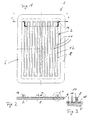
- the Fig. 1 to 4 show a first exemplary embodiment of the invention of a plane mirror glass.
- the mirror is rectangular with rounded corners.
- the FIGS. 1 to 4 show a first embodiment of a mirror glass 1 according to the present invention.
- the mirror pane 1 according to the first embodiment consists of a planar plastic substrate 2 with a front side 4 and a rear side 6.
- the plastic substrate 2 is provided with an electrodeposited metal layer 8 both on the front side 4 and on the rear side 6.
- This metal layer 8 consists of several metal layers, wherein the uppermost layer is a chromium layer which serves as a mirror layer on the front side 4.
- a surface heating device 10 with a meandering resistance heating conductor 12 and two electrical connection contacts 14 is integrated in the galvanic coating of the plastic substrate 2.
- the integral production of the heating conductor 12 on the rear side 6 of the plastic substrate 2 can alternatively also take place in that instead of covering the regions of the negative image of the resistance heating conductor 12 and electrical connections 14, a treatment of the plastic substrate 2 is carried out, which does not cause these surfaces the metal layer 8 are provided so that result in metal-free recesses 13, which release the plastic substrate 2 partially.
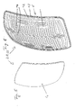
- FIGS. 5 and 6 show a second exemplary embodiment of a mirror plate 20 with a plastic substrate 22 whose front side 4 is convexly curved.
- Fig. 5 shows the front side 4 of the mirror plate 20
- Fig. 6 the meandering heating conductor 12 is designed so that even larger gaps 24 between individual turns of the heating element 12 result, which serve to receive fastening elements, not shown.
- the coating of the mirror plate 20 with the metal layer 8 is also galvanic and also the surface heater 10 can be provided in the same manner on the back 6.
- the resistance heating conductor 12 also ends in two electrical connection contacts 26, which are designed in contrast to the first embodiment as flat contacts and not as projections.
- the surface heater 10 in both the first and second embodiments may be provided by first completely coating the plastic substrate 2 and then partially removing the metal layer 8 on the back 6 of the plastic substrate 2 in the form of the negative image the heating conductor 12.
Abstract
Description
Die Erfindung betrifft eine Spiegelscheibe mit einem Substrat aus Kunststoff nach Anspruch 1, ein Verfahren zu deren Herstellung nach Anspruch 10 oder 12 sowie einen Außenspiegel mit einer solchen Spiegelscheibe nach Anspruch 16.The invention relates to a mirror pane with a plastic substrate according to
Spiegelscheiben mit einem Substrat aus Kunststoff deren Spiegelschicht aus einer Chromschicht besteht, die galvanisch auf dem Kunststoffsubstrat aufgebracht worden ist, sind bekannt. In der Regel werden solche Spiegel mit einer Flächenheizfolie versehen, bei der der Heizleiter zwischen einer Trägerfolie und einer Deckfolie angeordnet ist.Mirror disks with a plastic substrate whose mirror layer consists of a chromium layer which has been galvanically deposited on the plastic substrate are known. As a rule, such mirrors are provided with a surface heating foil, in which the heating conductor is arranged between a carrier foil and a cover foil.
In bestimmten Fällen ist es auch möglich, die Heizleiterbahnen direkt auf die Spiegelscheibe aufzudrucken. Dieses Verfahren ist jedoch insbesondere bei nicht planen Spiegelscheiben aufwendig. Aufgrund des geringen Gewichts des Kunststoffsubstrats im Vergleich zu Glas haben diese Spiegel den Vorteil des geringeren Gewichts. Allerdings ist die Herstellung vor allem aufgrund der aufwendigen Galvanisierung von Kunststoff im Vergleich zu Spiegeln aus Glas erheblich teurer, so dass sich derartige "Kunststoffspiegel" nur in Einzelfällen für Spezialanwendungen durchgesetzt haben.In certain cases, it is also possible to print the Heizleiterbahnen directly on the mirror glass. However, this method is particularly expensive for non-planar mirror discs. Due to the low weight of the plastic substrate compared to glass, these mirrors have the advantage of lower weight. However, the production is considerably more expensive, especially due to the complicated galvanization of plastic compared to mirrors made of glass, so that such "plastic mirrors" have prevailed only in isolated cases for special applications.
Eine Schutzschicht eines Heizleiters auf der Rückseite einer Spiegelscheibe ist aus
Die
Dazu offenbart
Ausgehend von
Dadurch, dass die Heizleiter der Heizeinrichtung Teil der galvanischen Beschichtung des Kunststoffsubstrats sind, entfallen die Kosten einer zusätzlichen Flächenheizvorrichtung in Form einer Flächenheizfolie. Die Flächenheizvorrichtung ist vielmehr integraler Bestandteil der Metallschicht auf der Rückseite des Kunststoffsubstrats. Auf der Vorderseite des Kunststoffsubstrats dient diese Metallschicht als Spiegelschicht.The fact that the heating conductors of the heating device are part of the galvanic coating of the plastic substrate eliminates the cost of an additional surface heating device in the form of a surface heating foil. The surface heating device is rather an integral part of the metal layer on the back of the plastic substrate. On the front side of the plastic substrate, this metal layer serves as a mirror layer.
Die Metallschicht kann mittels Sputtern hergestellt werden. Vorzugsweise erfolgt die Beschichtung des Kunststoffsubstrats jedoch durch einen galvanischen Abscheidungsprozess - Anspruch 2. Bei der galvanischen Beschichtung von Kunststoffteilen werden diese zunächst gebeizt, so dass sich ihre Oberfläche vergrößert. Danach wird die aufgeraute Kunststoffoberfläche durch Palladium aktiviert. Danach erfolgt stromlose das Aufbringen einer Nickelschicht. Nunmehr können verschiedene Metallschichten aus Kupfer, Nickel, Chrom etc. galvanisch abgeschieden werden.The metal layer can be produced by sputtering. However, the coating of the plastic substrate is preferably carried out by a galvanic deposition process -
Durch die vorteilhafte Ausgestaltung der Erfindung nach Anspruch 3 wird verhindert, dass bei Einsatz der Spiegelscheibe im Außenbereich durch Spritzwasser oder sonstige Umwelteinflüsse Kurzschlüsse entstehen.Due to the advantageous embodiment of the invention according to claim 3 prevents short circuits occur when using the mirror glass in the outdoor area by splashing or other environmental influences.
Durch die vorteilhafte Ausgestaltung der Erfindung nach Anspruch 4 ist das Kunststoffsubstrat auf der Rückseite mit Vorsprüngen versehen, die als Befestigungsmittel zur Befestigung der Spiegelscheibe an einer Spiegelträgerplatte und/oder als elektrische Anschlusskontakte für die Flächenheizeinrichtung dienen.Due to the advantageous embodiment of the invention according to
Durch die vorteilhafte Ausgestaltung der Erfindung nach Anspruch 5 sind diese Vorsprünge ebenfalls galvanisch beschichtet und so auf der Rückseite des Kunststoffsubstrats positioniert, dass sie an den Enden des Widerstandsheizleiters liegen und als elektrische Anschlusskontakte für die Flächenheizeinrichtung dienen. Auch hierdurch vereinfacht sich die Herstellung und sie wird kostengünstiger.Due to the advantageous embodiment of the invention according to claim 5, these projections are also galvanically coated and positioned on the back of the plastic substrate, that they are located at the ends of the Widerstandsheizleiters and serve as electrical connection contacts for the surface heater. This also simplifies the production and it is cheaper.
Gemäß der vorteilhaften Ausgestaltung der Erfindung nach Anspruch 6 sind diese Vorsprünge als Befestigungsmittel zur Befestigung der Spiegelscheibe an einer Spiegelträgerplatte ausgebildet. In diesem Fall ist eine Metallbeschichtung nicht notwendig. Die Spiegelscheibe kann daher auf einfache Weise an eine Spiegelträgerplatte montiert werden.According to the advantageous embodiment of the invention according to
Gemäß der vorteilhaften Ausgestaltung der Erfindung nach Anspruch 7 besteht die galvanisch auf der Spiegelscheibe aufgeschriebene Metallschicht, die zum einen als Spiegelreflexionsschicht dient und zum anderen die Heizleiter der Flächenheizeinrichtung bildet aus einer Mehrzahl von Schichten. Diese Schichten können aus unterschiedlichen Metallen bestehen oder aus dem gleichen Metall, das in mehreren getrennten Arbeitsgängen abgeschieden wird. Hierdurch können die optischen Eigenschaften der Spiegelschicht gezielt beeinflusst werden. Auch können auf diese Weise z. b. durch das Vorsehen einer "weichen" Kupferschicht Unterschiede in den Wärmeausdehnungskoeffizienten zwischen Kunststoffsubstrat und Metallschicht ausgeglichen werdenAccording to the advantageous embodiment of the invention according to claim 7, there is the galvanically written on the mirror plate metal layer, which serves as a mirror reflection layer and on the other hand, the heating element of the surface heater is formed of a plurality of layers. These layers may consist of different metals or of the same metal that is deposited in several separate operations. As a result, the optical properties of the mirror layer can be influenced in a targeted manner. Also, in this way, for. b. differences in the thermal expansion coefficients between plastic substrate and metal layer can be compensated for by providing a "soft" copper layer
Durch die vorteilhafte Ausgestaltung der Spiegelscheibe nach Anspruch 8 wird die Spiegelfunktion optimiert.Due to the advantageous embodiment of the mirror glass according to
Das galvanische Aufbringen der Metallschicht, die auch als Spiegelschicht dient, bedingt, dass das ganze Bauteil beschichtet wird, sofern entsprechende Flächen nicht entsprechend behandelt werden. Indem des Negativbild der Widerstandsheizleiter der Flächenheizeinrichtung so behandelt bzw. abgedeckt wird, dass bei der Galvanisierung sich an diesen Stellen kein Metall abscheidet, wird die Flächenheizeinrichtung integral bei der galvanischen Abscheidung der Metallschicht hergestellt - Anspruch 10. Hierdurch wird die Flächenheizeinrichtunq in einem Verfahrensgang mit der Metallschicht hergestellt, was die Herstellung vereinfacht und daher konstengünstiger macht.The galvanic application of the metal layer, which also serves as a mirror layer, requires that the entire component is coated unless appropriate surfaces are treated accordingly. By treating the negative image of the resistance heating conductors of the surface heating device in such a way that no metal deposits at the electroplating in these places, the surface heating device is produced integrally in the electrodeposition of the metal layer - claim 10. This makes the surface heating device one process step made with the metal layer, which simplifies the production and therefore makes konstengünstiger.
Alternativ ist es auch möglich, die Oberfläche des Kunststoffsubstrats vollständig zu beschichten. Der Widerstandsheizleiter bzw. die Widerstandsheizleiter der Flächenheizeinrichtung wird/werden danach hergestellt, in dem die Metallschicht zwischen den Widerstandsheizleitern z. B. durch mechanische Bearbeitung wieder entfernt wird - Anspruch 12.Alternatively, it is also possible to fully coat the surface of the plastic substrate. The Widerstandsheizleiter or Widerstandsheizleiter the surface heater is / are then prepared in which the metal layer between the Widerstandsheizleitern z. B. is removed again by mechanical processing -
Statt mechanischer Entfernung der Metallschicht kann dies auch mittels Ätzen - Anspruch 13 - oder mittels Laser - Anspruch 14 erfolgen.Instead of mechanical removal of the metal layer, this can also be done by means of etching - claim 13 - or by means of
Weitere Einzelheiten, Merkmale und Vorteile der Erfindung ergeben sich aus der nachfolgenden Beschreibung beispielhafter Ausführungsformen der Erfindung anhand der Zeichnung.Further details, features and advantages of the invention will become apparent from the following description of exemplary embodiments of the invention with reference to the drawing.
Es zeigt:
-
Fig. 1 eine Aufsicht auf die Rückseite einer ersten Ausführungsform der Erfindung, -
Fig. 2 eine Schnittdarstellung entlang der Linie A-A inFig. 1 , -
Fig. 3 ein Detail aus der Darstellung inFig. 2 , -
Fig. 4 zeigt eine Detailansicht des Anschlusskontaktes der ersten Ausführungsform, -
Fig. 5 eine perspektivische Darstellung einer Vorderansicht einer Spiegelscheibe gemäß einer zweiten Ausführungsform der Erfindung, und -
Fig. 6 eine Darstellung der Rückseite der Spiegelscheibe nachFig. 5 .
-
Fig. 1 a plan view of the back of a first embodiment of the invention, -
Fig. 2 a sectional view taken along the line AA inFig. 1 . -
Fig. 3 a detail from the illustration inFig. 2 . -
Fig. 4 shows a detailed view of the terminal contact of the first embodiment, -
Fig. 5 a perspective view of a front view of a mirror glass according to a second embodiment of the invention, and -
Fig. 6 a representation of the back of the mirror pane afterFig. 5 ,
Die
Die
Die integrale Herstellung des Heizleiters 12 auf der Rückseite 6 des Kunststoffsubstrats 2 kann alternativ auch dadurch erfolgen, dass anstelle einer Abdeckung der Bereiche des Negativbildes des Widerstandsheizleiters 12 und elektrischen Anschlüssen 14 eine Behandlung des Kunststoffsubstrats 2 durchgeführt wird, die bewirkt, dass diese Flächen nicht mit der Metallschicht 8 versehen werden, so dass sich metallfreie Ausnehmungen 13 ergeben, die das Kunststoffsubstrat 2 partiell freigeben.The integral production of the
Alternativ kann die Flächenheizeinrichtung 10 sowohl bei der ersten als auch bei der zweiten Ausführungsform dadurch bereitgestellt werden, dass zunächst das Kunststoffsubstrat 2 vollständig beschichtet wird, und danach die Metallschicht 8 auf der Rückseite 6 des Kunststoffsubstrats 2 teilweise wieder entfernt wird und zwar in Form des Negativbildes des Heizleiters 12.Alternatively, the surface heater 10 in both the first and second embodiments may be provided by first completely coating the
- 11
- Spiegelscheibemirror glass
- 22
- KunststoffsubstratPlastic substrate
- 44
- Vorderseitefront
- 66
- Rückseiteback
- 88th
- Metallschichtmetal layer
- 1010
- Flächenheizeinrichtungpanel heating
- 1111
- Isoliermaterialinsulating material
- 1212
- Widerstandsheizleiterresistance heating
- 1313
- Ausnehmungenrecesses
- 1414
- elektrische Anschlusskontakteelectrical connection contacts
- 1616
- Vorsprüngeprojections
- 1818
- Isolationsschichtinsulation layer
- 2020
- Spiegelscheibemirror glass
- 2222
- KunststoffsubstratPlastic substrate
- 2424
- Zwischenräume für BefestigungselementeIntermediate spaces for fasteners
- 2626
- elektrische Anschlusskontakteelectrical connection contacts
Claims (16)
einem Substrat (2; 22) aus Kunststoff, das eine Vorderseite (4) und
eine Rückseite (6) aufweist, die mit einer Metallschicht (8) versehen sind, und
einer Flächenheizeinrichtung (10) mit wenigstens einem Widerstandsheizleiter (12) und elektrischen Anschlusskontakten (14; 26), wobei die Metallschicht (8) auf der Vorderseite (4) des Substrats (2) als Spiegelschicht ausgebildet ist, und
wobei der wenigstens eine Widerstandsheizleiter (12) mit den elektrischen Anschlusskontakten (14; 26) durch die Metallschicht (8) auf der Rückseite (6) mit Ausnehmungen (13) in der Metallschicht (8) gebildet ist,
dadurch gekennzeichnet,
dass die Ausnehmungen (13) in der Metallschicht (8) in der Form des Negativbildes des wenigstens einen Widerstandsheizleiters (12) mit elektrischen Anschlusskontakten (14; 26) gebildet sind, und
dass das Substrat bis auf die Ausnehmungen (13) des Negativbildes vollständig mit Metall beschichtet ist.Mirror disc (1; 20), with
a plastic substrate (2; 22) having a front side (4) and
a rear side (6) provided with a metal layer (8), and
a Flächenheizeinrichtung (10) having at least one Widerstandsheizleiter (12) and electrical connection contacts (14; 26), wherein the metal layer (8) on the front side (4) of the substrate (2) is formed as a mirror layer, and
wherein the at least one resistance heating conductor (12) with the electrical connection contacts (14; 26) is formed by the metal layer (8) on the rear side (6) with recesses (13) in the metal layer (8),
characterized,
in that the recesses (13) in the metal layer (8) are formed in the form of the negative image of the at least one resistance heating conductor (12) with electrical connection contacts (14, 26), and
that the substrate is completely coated with metal except for the recesses (13) of the negative image.
Priority Applications (1)
| Application Number | Priority Date | Filing Date | Title |
|---|---|---|---|
| PL07150445T PL1973384T3 (en) | 2007-03-21 | 2007-12-27 | Reflective sheet with a plastic substrate, a method for the production thereof as well as an outside mirror with such a reflective sheet |
Applications Claiming Priority (1)
| Application Number | Priority Date | Filing Date | Title |
|---|---|---|---|
| DE102007013598A DE102007013598B3 (en) | 2007-03-21 | 2007-03-21 | Flat mirror panel for use in outside mirror of motor vehicle, has recesses provided in shape of negative print of heating conductor with connection contacts, and substrate completely coated with metal up to recesses of negative print |
Publications (2)
| Publication Number | Publication Date |
|---|---|
| EP1973384A1 true EP1973384A1 (en) | 2008-09-24 |
| EP1973384B1 EP1973384B1 (en) | 2010-02-24 |
Family
ID=38933263
Family Applications (1)
| Application Number | Title | Priority Date | Filing Date |
|---|---|---|---|
| EP07150445A Not-in-force EP1973384B1 (en) | 2007-03-21 | 2007-12-27 | Reflective sheet with a plastic substrate, a method for the production thereof as well as an outside mirror with such a reflective sheet |
Country Status (7)
| Country | Link |
|---|---|
| US (1) | US20080239530A1 (en) |
| EP (1) | EP1973384B1 (en) |
| AT (1) | ATE459228T1 (en) |
| BR (1) | BRPI0800610A2 (en) |
| DE (2) | DE102007013598B3 (en) |
| ES (1) | ES2338928T3 (en) |
| PL (1) | PL1973384T3 (en) |
Cited By (2)
| Publication number | Priority date | Publication date | Assignee | Title |
|---|---|---|---|---|
| EP2112022B2 (en) † | 2008-04-23 | 2014-12-10 | SMR Patents S.à.r.l. | Plastic glass mirror for vehicles |
| DE102012108592C5 (en) * | 2012-09-14 | 2019-02-14 | SMR Patents S.à.r.l. | Rear view mirror unit |
Families Citing this family (4)
| Publication number | Priority date | Publication date | Assignee | Title |
|---|---|---|---|---|
| EP2315495B1 (en) * | 2009-10-22 | 2013-11-06 | SMR Patents S.à.r.l. | Process to apply heater function to plastic glass |
| DE102010056493A1 (en) * | 2010-12-30 | 2012-07-05 | Polyic Gmbh & Co. Kg | Heated mirror |
| DE102013203530A1 (en) * | 2013-03-01 | 2014-09-04 | Magna Mirrors Holding Gmbh | Rearview mirror assembly for motor vehicles |
| DE102022202354B3 (en) | 2022-03-09 | 2023-01-12 | Magna Mirrors Holding Gmbh | Glass assembly for a rearview mirror assembly for motor vehicles, and method for manufacturing a glass assembly |
Citations (8)
| Publication number | Priority date | Publication date | Assignee | Title |
|---|---|---|---|---|
| DE3309024C2 (en) | 1983-03-14 | 1988-09-08 | Deutsche Spezialglas Ag, 3223 Delligsen, De | |
| FR2695789A1 (en) * | 1992-09-15 | 1994-03-18 | Techmeta | Heated mirror - with reflection surface contg. sufficient chromium oxide to produce required electrical resistance conferring required heating effect |
| WO1999062303A1 (en) * | 1998-05-28 | 1999-12-02 | Isoclima S.P.A. | Heated mirror, particularly for vehicles, and method for manufacturing it |
| DE19860941A1 (en) * | 1998-12-29 | 2000-07-13 | Magna Reflex Holding Gmbh | Vehicle rear view system with electrochromic mirror |
| US20040071983A1 (en) * | 1998-05-28 | 2004-04-15 | Isoclima S.P.A. | Heated mirror, particularly for vehicles, and method for manufacturing it |
| EP1566318A1 (en) * | 2002-11-28 | 2005-08-24 | Nok Corporation | Door mirror heater |
| DE102005054611A1 (en) | 2004-11-09 | 2006-05-18 | Creavac Creative Vakuumbeschichtung Gmbh | Production process for meandering layers on a substrate as for heating elements uses two templates to form two layers of mirror image Z shaped forms |
| EP1510105B1 (en) * | 2002-05-31 | 2006-08-30 | Schefenacker Vision Systems France S.A. | Heated mirror |
Family Cites Families (12)
| Publication number | Priority date | Publication date | Assignee | Title |
|---|---|---|---|---|
| US3798419A (en) * | 1973-03-12 | 1974-03-19 | Gould Inc | Electrical surface heating assembly |
| US4071736A (en) * | 1976-02-12 | 1978-01-31 | Donnelly Mirrors, Inc. | Defrosting mirror |
| US4237366A (en) * | 1979-03-19 | 1980-12-02 | Texas Instruments Incorporated | Heated automobile mirror |
| US4410790A (en) * | 1981-12-17 | 1983-10-18 | Texas Instruments Incorporated | Heated automobile mirror |
| US4459470A (en) * | 1982-01-26 | 1984-07-10 | The United States Of America As Represented By The Administrator Of The National Aeronautics And Space Administration | Glass heating panels and method for preparing the same from architectural reflective glass |
| US4634242A (en) * | 1983-07-11 | 1987-01-06 | Nippon Soken, Inc. | Defrostable outside rear view mirror for an automobile |
| JPS60145594U (en) * | 1984-03-02 | 1985-09-27 | 東京コスモス電機株式会社 | Resistor element for planar heating element |
| US4942286A (en) * | 1987-11-13 | 1990-07-17 | Thermacon, Inc. | Apparatus for heating a mirror or the like |
| JPH0811631A (en) * | 1994-06-29 | 1996-01-16 | Murakami Kaimeidou:Kk | Mirror for vehicle |
| DE69532622T2 (en) * | 1994-12-07 | 2005-02-03 | Tokyo Cosmos Electric Co. Ltd., , Hachioji | Surface heating element for use in mirrors |
| DE29606416U1 (en) * | 1996-04-06 | 1996-06-27 | Mekra Rangau Plastics | Exterior rear-view mirrors for motor vehicles, in particular commercial vehicles |
| US6426485B1 (en) * | 2001-07-31 | 2002-07-30 | Illinois Tool Works Inc. | Light diffusing signal mirror heater |
-
2007
- 2007-03-21 DE DE102007013598A patent/DE102007013598B3/en not_active Expired - Fee Related
- 2007-12-27 EP EP07150445A patent/EP1973384B1/en not_active Not-in-force
- 2007-12-27 AT AT07150445T patent/ATE459228T1/en active
- 2007-12-27 PL PL07150445T patent/PL1973384T3/en unknown
- 2007-12-27 ES ES07150445T patent/ES2338928T3/en active Active
- 2007-12-27 DE DE502007002920T patent/DE502007002920D1/en active Active
-
2008
- 2008-03-18 US US12/077,218 patent/US20080239530A1/en not_active Abandoned
- 2008-03-20 BR BRPI0800610-5A patent/BRPI0800610A2/en not_active IP Right Cessation
Patent Citations (9)
| Publication number | Priority date | Publication date | Assignee | Title |
|---|---|---|---|---|
| DE3309024C2 (en) | 1983-03-14 | 1988-09-08 | Deutsche Spezialglas Ag, 3223 Delligsen, De | |
| FR2695789A1 (en) * | 1992-09-15 | 1994-03-18 | Techmeta | Heated mirror - with reflection surface contg. sufficient chromium oxide to produce required electrical resistance conferring required heating effect |
| WO1999062303A1 (en) * | 1998-05-28 | 1999-12-02 | Isoclima S.P.A. | Heated mirror, particularly for vehicles, and method for manufacturing it |
| US20040071983A1 (en) * | 1998-05-28 | 2004-04-15 | Isoclima S.P.A. | Heated mirror, particularly for vehicles, and method for manufacturing it |
| DE19860941A1 (en) * | 1998-12-29 | 2000-07-13 | Magna Reflex Holding Gmbh | Vehicle rear view system with electrochromic mirror |
| EP1510105B1 (en) * | 2002-05-31 | 2006-08-30 | Schefenacker Vision Systems France S.A. | Heated mirror |
| DE60308022T2 (en) | 2002-05-31 | 2007-04-12 | Schefenacker Vision Systems France S.A. | HEATED MIRROR |
| EP1566318A1 (en) * | 2002-11-28 | 2005-08-24 | Nok Corporation | Door mirror heater |
| DE102005054611A1 (en) | 2004-11-09 | 2006-05-18 | Creavac Creative Vakuumbeschichtung Gmbh | Production process for meandering layers on a substrate as for heating elements uses two templates to form two layers of mirror image Z shaped forms |
Cited By (2)
| Publication number | Priority date | Publication date | Assignee | Title |
|---|---|---|---|---|
| EP2112022B2 (en) † | 2008-04-23 | 2014-12-10 | SMR Patents S.à.r.l. | Plastic glass mirror for vehicles |
| DE102012108592C5 (en) * | 2012-09-14 | 2019-02-14 | SMR Patents S.à.r.l. | Rear view mirror unit |
Also Published As
| Publication number | Publication date |
|---|---|
| US20080239530A1 (en) | 2008-10-02 |
| PL1973384T3 (en) | 2010-07-30 |
| EP1973384B1 (en) | 2010-02-24 |
| BRPI0800610A2 (en) | 2009-03-17 |
| ATE459228T1 (en) | 2010-03-15 |
| DE502007002920D1 (en) | 2010-04-08 |
| DE102007013598B3 (en) | 2008-05-08 |
| ES2338928T3 (en) | 2010-05-13 |
Similar Documents
| Publication | Publication Date | Title |
|---|---|---|
| EP1973384B1 (en) | Reflective sheet with a plastic substrate, a method for the production thereof as well as an outside mirror with such a reflective sheet | |
| DE10208674B4 (en) | Process for the production of electroplated elements with backlightable symbols and elements produced by the process | |
| EP0839360B1 (en) | Method and device for producing an IC-card module | |
| DE212011100046U1 (en) | Transparent disc with heating coating | |
| WO2016034413A1 (en) | Panel having electrical heating area | |
| DE202008017988U1 (en) | Transparent display device with tracks provided with an opaque coating | |
| DE8535648U1 (en) | Laminated glass for vehicles | |
| DE102011014902B3 (en) | Producing an antenna component with a three-dimensional antenna, comprises forming an electrical conductive layer made of an electrical conductive lacquer onto a thermoplastic carrier foil in an antenna area formed as antenna structure | |
| DE10112731A1 (en) | Coating of substrates | |
| DE112008002043T5 (en) | A method of providing a contact on the back of a solar cell and a solar cell with contacts provided in accordance with the method | |
| EP2009970A2 (en) | Method for manufacturing an electrically conductive structure | |
| DE102004029164A1 (en) | Composite glass pane with segmented conducting coating has bus bar arrangement with at least two mutually parallel adjacent bus bars covered by insulating coating on side facing conducting coating | |
| DE60036043T2 (en) | Disc for motor vehicles with heatable rest position for windscreen wipers | |
| DE19731969A1 (en) | Manufacturing method e.g. for electrical component having conductive structure on thermoplastic carrier substrate, such as chipcard-transponder | |
| DE19608661C2 (en) | Electrical contact and method for producing the electrical contact for connection to a conductive arrangement located on an insulating substrate, in particular for motor vehicle windows | |
| EP1696705B1 (en) | Flat heating element of small thickness, in particular for cooking oven | |
| DE2234366A1 (en) | METHOD OF MANUFACTURING ELECTRICAL WIRING ARRANGEMENTS | |
| DE2701373C2 (en) | Process for producing a resistive layer of metal film ignition means | |
| DE19602354C2 (en) | sensor | |
| WO2000070396A1 (en) | Liquid crystal display | |
| DE19780905C2 (en) | Resistance and process for its manufacture | |
| DE3034175A1 (en) | Chemical deposition of electrically conducting layers - where electrical properties of deposit are used to indicate end of deposition process, esp. in mfg. electronic components | |
| DE202019004359U1 (en) | Beam lead element | |
| EP1577133A2 (en) | Vehicle panes, protective foils and overprints and maufacturing process therefor | |
| DE19532223C1 (en) | Chip card contg. chip module embedded in card having at least two metallisation areas |
Legal Events
| Date | Code | Title | Description |
|---|---|---|---|
| PUAI | Public reference made under article 153(3) epc to a published international application that has entered the european phase |
Free format text: ORIGINAL CODE: 0009012 |
|
| 17P | Request for examination filed |
Effective date: 20080423 |
|
| AK | Designated contracting states |
Kind code of ref document: A1 Designated state(s): AT BE BG CH CY CZ DE DK EE ES FI FR GB GR HU IE IS IT LI LT LU LV MC MT NL PL PT RO SE SI SK TR |
|
| AX | Request for extension of the european patent |
Extension state: AL BA HR MK RS |
|
| AKX | Designation fees paid |
Designated state(s): AT BE BG CH CY CZ DE DK EE ES FI FR GB GR HU IE IS IT LI LT LU LV MC MT NL PL PT RO SE SI SK TR |
|
| GRAP | Despatch of communication of intention to grant a patent |
Free format text: ORIGINAL CODE: EPIDOSNIGR1 |
|
| GRAS | Grant fee paid |
Free format text: ORIGINAL CODE: EPIDOSNIGR3 |
|
| RAP1 | Party data changed (applicant data changed or rights of an application transferred) |
Owner name: MEKRA LANG GMBH & CO. KG |
|
| GRAA | (expected) grant |
Free format text: ORIGINAL CODE: 0009210 |
|
| AK | Designated contracting states |
Kind code of ref document: B1 Designated state(s): AT BE BG CH CY CZ DE DK EE ES FI FR GB GR HU IE IS IT LI LT LU LV MC MT NL PL PT RO SE SI SK TR |
|
| REG | Reference to a national code |
Ref country code: GB Ref legal event code: FG4D Free format text: NOT ENGLISH |
|
| REG | Reference to a national code |
Ref country code: CH Ref legal event code: EP |
|
| REG | Reference to a national code |
Ref country code: IE Ref legal event code: FG4D Free format text: LANGUAGE OF EP DOCUMENT: GERMAN |
|
| REF | Corresponds to: |
Ref document number: 502007002920 Country of ref document: DE Date of ref document: 20100408 Kind code of ref document: P |
|
| REG | Reference to a national code |
Ref country code: ES Ref legal event code: FG2A Ref document number: 2338928 Country of ref document: ES Kind code of ref document: T3 |
|
| REG | Reference to a national code |
Ref country code: SE Ref legal event code: TRGR |
|
| REG | Reference to a national code |
Ref country code: NL Ref legal event code: VDEP Effective date: 20100224 |
|
| LTIE | Lt: invalidation of european patent or patent extension |
Effective date: 20100224 |
|
| PG25 | Lapsed in a contracting state [announced via postgrant information from national office to epo] |
Ref country code: IS Free format text: LAPSE BECAUSE OF FAILURE TO SUBMIT A TRANSLATION OF THE DESCRIPTION OR TO PAY THE FEE WITHIN THE PRESCRIBED TIME-LIMIT Effective date: 20100624 Ref country code: PT Free format text: LAPSE BECAUSE OF FAILURE TO SUBMIT A TRANSLATION OF THE DESCRIPTION OR TO PAY THE FEE WITHIN THE PRESCRIBED TIME-LIMIT Effective date: 20100625 Ref country code: LT Free format text: LAPSE BECAUSE OF FAILURE TO SUBMIT A TRANSLATION OF THE DESCRIPTION OR TO PAY THE FEE WITHIN THE PRESCRIBED TIME-LIMIT Effective date: 20100224 |
|
| REG | Reference to a national code |
Ref country code: PL Ref legal event code: T3 |
|
| PG25 | Lapsed in a contracting state [announced via postgrant information from national office to epo] |
Ref country code: FI Free format text: LAPSE BECAUSE OF FAILURE TO SUBMIT A TRANSLATION OF THE DESCRIPTION OR TO PAY THE FEE WITHIN THE PRESCRIBED TIME-LIMIT Effective date: 20100224 Ref country code: LV Free format text: LAPSE BECAUSE OF FAILURE TO SUBMIT A TRANSLATION OF THE DESCRIPTION OR TO PAY THE FEE WITHIN THE PRESCRIBED TIME-LIMIT Effective date: 20100224 Ref country code: SI Free format text: LAPSE BECAUSE OF FAILURE TO SUBMIT A TRANSLATION OF THE DESCRIPTION OR TO PAY THE FEE WITHIN THE PRESCRIBED TIME-LIMIT Effective date: 20100224 |
|
| REG | Reference to a national code |
Ref country code: IE Ref legal event code: FD4D |
|
| PG25 | Lapsed in a contracting state [announced via postgrant information from national office to epo] |
Ref country code: NL Free format text: LAPSE BECAUSE OF FAILURE TO SUBMIT A TRANSLATION OF THE DESCRIPTION OR TO PAY THE FEE WITHIN THE PRESCRIBED TIME-LIMIT Effective date: 20100224 Ref country code: RO Free format text: LAPSE BECAUSE OF FAILURE TO SUBMIT A TRANSLATION OF THE DESCRIPTION OR TO PAY THE FEE WITHIN THE PRESCRIBED TIME-LIMIT Effective date: 20100224 Ref country code: CY Free format text: LAPSE BECAUSE OF FAILURE TO SUBMIT A TRANSLATION OF THE DESCRIPTION OR TO PAY THE FEE WITHIN THE PRESCRIBED TIME-LIMIT Effective date: 20100224 Ref country code: EE Free format text: LAPSE BECAUSE OF FAILURE TO SUBMIT A TRANSLATION OF THE DESCRIPTION OR TO PAY THE FEE WITHIN THE PRESCRIBED TIME-LIMIT Effective date: 20100224 Ref country code: GR Free format text: LAPSE BECAUSE OF FAILURE TO SUBMIT A TRANSLATION OF THE DESCRIPTION OR TO PAY THE FEE WITHIN THE PRESCRIBED TIME-LIMIT Effective date: 20100525 Ref country code: IE Free format text: LAPSE BECAUSE OF FAILURE TO SUBMIT A TRANSLATION OF THE DESCRIPTION OR TO PAY THE FEE WITHIN THE PRESCRIBED TIME-LIMIT Effective date: 20100224 |
|
| PG25 | Lapsed in a contracting state [announced via postgrant information from national office to epo] |
Ref country code: CZ Free format text: LAPSE BECAUSE OF FAILURE TO SUBMIT A TRANSLATION OF THE DESCRIPTION OR TO PAY THE FEE WITHIN THE PRESCRIBED TIME-LIMIT Effective date: 20100224 Ref country code: SK Free format text: LAPSE BECAUSE OF FAILURE TO SUBMIT A TRANSLATION OF THE DESCRIPTION OR TO PAY THE FEE WITHIN THE PRESCRIBED TIME-LIMIT Effective date: 20100224 Ref country code: BG Free format text: LAPSE BECAUSE OF FAILURE TO SUBMIT A TRANSLATION OF THE DESCRIPTION OR TO PAY THE FEE WITHIN THE PRESCRIBED TIME-LIMIT Effective date: 20100524 |
|
| PLBE | No opposition filed within time limit |
Free format text: ORIGINAL CODE: 0009261 |
|
| STAA | Information on the status of an ep patent application or granted ep patent |
Free format text: STATUS: NO OPPOSITION FILED WITHIN TIME LIMIT |
|
| PG25 | Lapsed in a contracting state [announced via postgrant information from national office to epo] |
Ref country code: DK Free format text: LAPSE BECAUSE OF FAILURE TO SUBMIT A TRANSLATION OF THE DESCRIPTION OR TO PAY THE FEE WITHIN THE PRESCRIBED TIME-LIMIT Effective date: 20100224 |
|
| PGFP | Annual fee paid to national office [announced via postgrant information from national office to epo] |
Ref country code: FR Payment date: 20110107 Year of fee payment: 4 |
|
| 26N | No opposition filed |
Effective date: 20101125 |
|
| PGFP | Annual fee paid to national office [announced via postgrant information from national office to epo] |
Ref country code: PL Payment date: 20101130 Year of fee payment: 4 |
|
| PGFP | Annual fee paid to national office [announced via postgrant information from national office to epo] |
Ref country code: SE Payment date: 20101221 Year of fee payment: 4 Ref country code: TR Payment date: 20101216 Year of fee payment: 4 |
|
| PGFP | Annual fee paid to national office [announced via postgrant information from national office to epo] |
Ref country code: DE Payment date: 20101130 Year of fee payment: 4 |
|
| BERE | Be: lapsed |
Owner name: MEKRA LANG G.M.B.H. & CO. KG Effective date: 20101231 |
|
| PGFP | Annual fee paid to national office [announced via postgrant information from national office to epo] |
Ref country code: ES Payment date: 20101222 Year of fee payment: 4 |
|
| PG25 | Lapsed in a contracting state [announced via postgrant information from national office to epo] |
Ref country code: MC Free format text: LAPSE BECAUSE OF NON-PAYMENT OF DUE FEES Effective date: 20101231 |
|
| PG25 | Lapsed in a contracting state [announced via postgrant information from national office to epo] |
Ref country code: BE Free format text: LAPSE BECAUSE OF NON-PAYMENT OF DUE FEES Effective date: 20101231 |
|
| PG25 | Lapsed in a contracting state [announced via postgrant information from national office to epo] |
Ref country code: IT Free format text: LAPSE BECAUSE OF NON-PAYMENT OF DUE FEES Effective date: 20101227 Ref country code: MT Free format text: LAPSE BECAUSE OF FAILURE TO SUBMIT A TRANSLATION OF THE DESCRIPTION OR TO PAY THE FEE WITHIN THE PRESCRIBED TIME-LIMIT Effective date: 20100224 |
|
| PGFP | Annual fee paid to national office [announced via postgrant information from national office to epo] |
Ref country code: IT Payment date: 20101231 Year of fee payment: 4 |
|
| REG | Reference to a national code |
Ref country code: CH Ref legal event code: PL Ref country code: SE Ref legal event code: EUG |
|
| GBPC | Gb: european patent ceased through non-payment of renewal fee |
Effective date: 20111227 |
|
| REG | Reference to a national code |
Ref country code: FR Ref legal event code: ST Effective date: 20120831 |
|
| PG25 | Lapsed in a contracting state [announced via postgrant information from national office to epo] |
Ref country code: LU Free format text: LAPSE BECAUSE OF NON-PAYMENT OF DUE FEES Effective date: 20101227 Ref country code: HU Free format text: LAPSE BECAUSE OF FAILURE TO SUBMIT A TRANSLATION OF THE DESCRIPTION OR TO PAY THE FEE WITHIN THE PRESCRIBED TIME-LIMIT Effective date: 20100825 |
|
| REG | Reference to a national code |
Ref country code: DE Ref legal event code: R119 Ref document number: 502007002920 Country of ref document: DE Effective date: 20120703 |
|
| PG25 | Lapsed in a contracting state [announced via postgrant information from national office to epo] |
Ref country code: LI Free format text: LAPSE BECAUSE OF NON-PAYMENT OF DUE FEES Effective date: 20111231 Ref country code: DE Free format text: LAPSE BECAUSE OF NON-PAYMENT OF DUE FEES Effective date: 20120703 Ref country code: SE Free format text: LAPSE BECAUSE OF NON-PAYMENT OF DUE FEES Effective date: 20111228 Ref country code: CH Free format text: LAPSE BECAUSE OF NON-PAYMENT OF DUE FEES Effective date: 20111231 Ref country code: GB Free format text: LAPSE BECAUSE OF NON-PAYMENT OF DUE FEES Effective date: 20111227 |
|
| PG25 | Lapsed in a contracting state [announced via postgrant information from national office to epo] |
Ref country code: IT Free format text: LAPSE BECAUSE OF NON-PAYMENT OF DUE FEES Effective date: 20111227 |
|
| REG | Reference to a national code |
Ref country code: PL Ref legal event code: LAPE |
|
| PG25 | Lapsed in a contracting state [announced via postgrant information from national office to epo] |
Ref country code: FR Free format text: LAPSE BECAUSE OF NON-PAYMENT OF DUE FEES Effective date: 20120102 |
|
| PG25 | Lapsed in a contracting state [announced via postgrant information from national office to epo] |
Ref country code: PL Free format text: LAPSE BECAUSE OF NON-PAYMENT OF DUE FEES Effective date: 20111227 |
|
| REG | Reference to a national code |
Ref country code: ES Ref legal event code: FD2A Effective date: 20130716 |
|
| PG25 | Lapsed in a contracting state [announced via postgrant information from national office to epo] |
Ref country code: ES Free format text: LAPSE BECAUSE OF NON-PAYMENT OF DUE FEES Effective date: 20111228 |
|
| PG25 | Lapsed in a contracting state [announced via postgrant information from national office to epo] |
Ref country code: TR Free format text: LAPSE BECAUSE OF NON-PAYMENT OF DUE FEES Effective date: 20111227 |
|
| REG | Reference to a national code |
Ref country code: AT Ref legal event code: MM01 Ref document number: 459228 Country of ref document: AT Kind code of ref document: T Effective date: 20121227 |
|
| PG25 | Lapsed in a contracting state [announced via postgrant information from national office to epo] |
Ref country code: AT Free format text: LAPSE BECAUSE OF NON-PAYMENT OF DUE FEES Effective date: 20121227 |