EP1973019A1 - Device for judging collision of a die cushion mechanism and system for judging collision - Google Patents
Device for judging collision of a die cushion mechanism and system for judging collision Download PDFInfo
- Publication number
- EP1973019A1 EP1973019A1 EP08010486A EP08010486A EP1973019A1 EP 1973019 A1 EP1973019 A1 EP 1973019A1 EP 08010486 A EP08010486 A EP 08010486A EP 08010486 A EP08010486 A EP 08010486A EP 1973019 A1 EP1973019 A1 EP 1973019A1
- Authority
- EP
- European Patent Office
- Prior art keywords
- slide
- collision
- die cushion
- force
- value
- Prior art date
- Legal status (The legal status is an assumption and is not a legal conclusion. Google has not performed a legal analysis and makes no representation as to the accuracy of the status listed.)
- Withdrawn
Links
- 230000007246 mechanism Effects 0.000 title claims abstract description 45
- 238000001514 detection method Methods 0.000 claims abstract description 193
- 238000000034 method Methods 0.000 abstract description 21
- 230000001133 acceleration Effects 0.000 description 14
- 230000004069 differentiation Effects 0.000 description 9
- 238000010586 diagram Methods 0.000 description 8
- 239000000463 material Substances 0.000 description 5
- 230000036316 preload Effects 0.000 description 5
- 238000012545 processing Methods 0.000 description 4
- 238000012986 modification Methods 0.000 description 2
- 230000004048 modification Effects 0.000 description 2
- 238000000465 moulding Methods 0.000 description 2
- 238000007792 addition Methods 0.000 description 1
- 238000013459 approach Methods 0.000 description 1
- 238000005452 bending Methods 0.000 description 1
- 239000013013 elastic material Substances 0.000 description 1
- 238000002474 experimental method Methods 0.000 description 1
- 230000002093 peripheral effect Effects 0.000 description 1
- 238000004080 punching Methods 0.000 description 1
- 230000004044 response Effects 0.000 description 1
- 230000000630 rising effect Effects 0.000 description 1
- 230000037303 wrinkles Effects 0.000 description 1
Images


Classifications
-
- B—PERFORMING OPERATIONS; TRANSPORTING
- B21—MECHANICAL METAL-WORKING WITHOUT ESSENTIALLY REMOVING MATERIAL; PUNCHING METAL
- B21D—WORKING OR PROCESSING OF SHEET METAL OR METAL TUBES, RODS OR PROFILES WITHOUT ESSENTIALLY REMOVING MATERIAL; PUNCHING METAL
- B21D24/00—Special deep-drawing arrangements in, or in connection with, presses
- B21D24/10—Devices controlling or operating blank holders independently, or in conjunction with dies
-
- G—PHYSICS
- G05—CONTROLLING; REGULATING
- G05B—CONTROL OR REGULATING SYSTEMS IN GENERAL; FUNCTIONAL ELEMENTS OF SUCH SYSTEMS; MONITORING OR TESTING ARRANGEMENTS FOR SUCH SYSTEMS OR ELEMENTS
- G05B19/00—Programme-control systems
- G05B19/02—Programme-control systems electric
- G05B19/18—Numerical control [NC], i.e. automatically operating machines, in particular machine tools, e.g. in a manufacturing environment, so as to execute positioning, movement or co-ordinated operations by means of programme data in numerical form
- G05B19/19—Numerical control [NC], i.e. automatically operating machines, in particular machine tools, e.g. in a manufacturing environment, so as to execute positioning, movement or co-ordinated operations by means of programme data in numerical form characterised by positioning or contouring control systems, e.g. to control position from one programmed point to another or to control movement along a programmed continuous path
-
- G—PHYSICS
- G05—CONTROLLING; REGULATING
- G05B—CONTROL OR REGULATING SYSTEMS IN GENERAL; FUNCTIONAL ELEMENTS OF SUCH SYSTEMS; MONITORING OR TESTING ARRANGEMENTS FOR SUCH SYSTEMS OR ELEMENTS
- G05B2219/00—Program-control systems
- G05B2219/30—Nc systems
- G05B2219/37—Measurements
- G05B2219/37411—Measure contact from force and velocity detection
-
- G—PHYSICS
- G05—CONTROLLING; REGULATING
- G05B—CONTROL OR REGULATING SYSTEMS IN GENERAL; FUNCTIONAL ELEMENTS OF SUCH SYSTEMS; MONITORING OR TESTING ARRANGEMENTS FOR SUCH SYSTEMS OR ELEMENTS
- G05B2219/00—Program-control systems
- G05B2219/30—Nc systems
- G05B2219/37—Measurements
- G05B2219/37622—Detect collision, blocking, stall by change, lag in position
-
- G—PHYSICS
- G05—CONTROLLING; REGULATING
- G05B—CONTROL OR REGULATING SYSTEMS IN GENERAL; FUNCTIONAL ELEMENTS OF SUCH SYSTEMS; MONITORING OR TESTING ARRANGEMENTS FOR SUCH SYSTEMS OR ELEMENTS
- G05B2219/00—Program-control systems
- G05B2219/30—Nc systems
- G05B2219/37—Measurements
- G05B2219/37624—Detect collision, blocking by measuring change of velocity or torque
-
- G—PHYSICS
- G05—CONTROLLING; REGULATING
- G05B—CONTROL OR REGULATING SYSTEMS IN GENERAL; FUNCTIONAL ELEMENTS OF SUCH SYSTEMS; MONITORING OR TESTING ARRANGEMENTS FOR SUCH SYSTEMS OR ELEMENTS
- G05B2219/00—Program-control systems
- G05B2219/30—Nc systems
- G05B2219/42—Servomotor, servo controller kind till VSS
- G05B2219/42123—Position loop then force, current loop
-
- G—PHYSICS
- G05—CONTROLLING; REGULATING
- G05B—CONTROL OR REGULATING SYSTEMS IN GENERAL; FUNCTIONAL ELEMENTS OF SUCH SYSTEMS; MONITORING OR TESTING ARRANGEMENTS FOR SUCH SYSTEMS OR ELEMENTS
- G05B2219/00—Program-control systems
- G05B2219/30—Nc systems
- G05B2219/45—Nc applications
- G05B2219/45131—Turret punch press
Definitions
- the present invention relates to a device for judging the collision of a slide with a die cushion in a die cushion mechanism and a system for judging the collision.
- a die cushion mechanism as an accessory unit for applying a predetermined force (pressure) from the side of a support member (usually called bolster) that supports a second mold to another support member (usually called slide) of the moving side that supports a first mold used for the press work during the working operation.
- the die cushion mechanism is usually so constituted that a cushion pad moves together with a slide while applying a force (pressure) to the slide after the slide (or the first mold) moving in a direction of closing the mold is brought into direct or indirect collision with a moving element (usually called cushion pad) and is held with a predetermined pressure until the mold is opened after the mold is closed (molding). During this period, the peripheral region of a working portion of a material to be worked is held between the cushion pad and the slide to prevent the occurrence of wrinkles in the material to be worked.
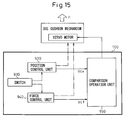
- Fig. 15 is a functional block diagram of a control device for the die cushion mechanism according to a prior art.
- a position control unit 920 and a force control unit 940 in the control device 100 produce a position control speed instruction value Vcx and a force control speed instruction value Vcf based on their respective predetermined control systems.
- the position control speed instruction value Vcs and the force control speed instruction value Vcf are, then, fed to a comparison operation unit 950.
- the comparison operation unit 950 compares the downward magnitudes of the position control speed instruction value Vcs and of the force control speed instruction value Vcf, i.e., compares the speeds in the direction in which the slide moves down toward the cushion pad.
- a switch 930 is so changed over that the die cushion is controlled by the position control unit 920.
- the switch 930 is so changed over that the die cushion is controlled by the force control unit 940.
- the slide in the die cushion mechanism at first stands by at its upper-limit position.
- the position control speed instruction value Vcx is greater than the force control speed instruction value Vcf. Therefore, due to the switch 930, the die cushion starts moving down based on the position control speed instruction value Vcx fed from the position control unit 920.
- the comparison processing by the comparison operation unit 950 is repetitively executed while the slide is moving down.
- the force control speed instruction value Vcf becomes greater than the position control speed instruction value Vcx, it is so judged that the slide has come into collision with the die cushion, and the position control unit 920 is switched over to the force control unit 940 by the switch 930. Therefore, the die cushion moves down based on the force control speed instruction value Vcf of the force control unit 940 to produce a suitable cushion pressure.
- the slide when the slide is going to come into collision with the die cushion, the slide, first, comes into contact with a cushion pin whereby the slide and a cushion pad move down integrally and together.
- the cushion pin When the force of the cushion pad acting on the damper increases, the cushion pin further moves down, and the bolster of the die cushion comes into collision with the slide via their respective molds.
- an incorrect judgement of collision may render the die cushion mechanism to be in a state where the press work can no longer be executed. Therefore, it is necessary to reliably judge the collision of the slide with the cushion pad.
- the present invention was accomplished in view of the above-mentioned circumstances, and has an object of providing a device, for judging the collision of a die cushion mechanism, which is capable of judging the collision between the slide and the cushion pad within a short period of time and reliably, and a system for judging the collision.
- a device for judging the collision of a slide with a die cushion in a die cushion mechanism which produces a force against the slide in a press machine using a servo motor, as a drive source, comprising:
- a device for judging the collision of a slide with a die cushion in a die cushion mechanism which produces a force against the slide in a press machine using a servo motor as a drive source, comprising:
- a device for judging the collision of a slide with a die cushion in a die cushion mechanism which produces a force against the slide in a press machine using a servo motor as a drive source, comprising:
- a device for judging the collision of a slide with a die cushion in a die cushion mechanism which produces a force against the slide in a press machine using a servo motor as a drive source, comprising:
- a device for judging the collision of a slide with a die cushion in a die cushion mechanism which produces a force against the slide in a press machine using a servo motor as a drive source, comprising:
- the first aspect judges the collision by detecting a force detection value only and by comparing it with a predetermined threshold value
- the second aspect judges the collision by detecting a force detection value only and by comparing it with a force detection value, of before the operation, that has been detected in advance
- the third aspect judges the collision by detecting a force detection value only and by comparing it, after having put it through first-order differentiation, with a predetermined threshold value
- the fourth aspect judges the collision by detecting a force detection value only and by comparing it, after having put it through second-order differentiation, with a predetermined threshold value
- the fifth aspect judges the collision by detecting a force detection value only and by comparing it with a force instruction value.
- the first to fifth aspects therefore, there is no need to use the force control speed instruction value and the position control speed instruction value at the time of judging the collision, and the collision can be judged within a short period of time.
- a device for judging the collision of a slide with a die cushion in a die cushion mechanism which produces a force against the slide in a press machine using a servo motor as a drive source, comprising:
- a device for judging the collision of a slide with a die cushion in a die cushion mechanism which produces a force for the slide in a press machine using a servo motor as a drive source, comprising:
- a device for judging the collision of a slide with a die cushion in a die cushion mechanism which produces a force against the slide in a press machine using a servo motor as a drive source, comprising:
- the sixth aspect judges the collision by detecting a speed detection value only and by comparing it with a predetermined threshold value
- the seventh aspect judges the collision by detecting a speed detection value only and by comparing it, after having put it through first-order differentiation, with a predetermined threshold value
- the eighth aspect judges the collision by detecting an acceleration detection value only and by comparing it with a predetermined threshold value.
- a device for judging the collision of a slide with a die cushion in a die cushion mechanism which produces a force against the slide in a press machine using a servo motor as a drive source, comprising:
- a device for judging the collision of a slide with a die cushion in a die cushion mechanism which produces a force against the slide in a press machine using a servo motor as a drive source, comprising:
- a device for judging the collision of a slide with a die cushion in a die cushion mechanism which produces a force against the slide in a press machine using a servo motor as a drive source, comprising:
- a device for judging the collision of a slide with a die cushion in a die cushion mechanism which produces a force against the slide in a press machine using a servo motor as a drive source, comprising:
- a device for judging the collision of a slide with a die cushion in a die cushion mechanism which produces a force against the slide in a press machine using a servo motor as a drive source, comprising:
- a device for judging the collision of a slide with a die cushion in a die cushion mechanism which produces a force against the slide in a press machine using a servo motor as a drive source, comprising:
- a device for judging the collision of a slide with a die cushion in a die cushion mechanism which produces a force against the slide in a press machine using a servo motor as a drive source, comprising:
- the ninth aspect judges the collision by detecting a slide position detection value only and by comparing it with a predetermined threshold value
- the tenth aspect judges the collision by using a slide position instruction value only and by comparing it with a predetermined threshold value
- the eleventh aspect judges the collision by detecting only a distance between the slide and the die cushion, and by comparing it with a predetermined threshold value
- the twelfth and thirteenth aspects judge the collision by detecting a slide position detection value and a die cushion position detection value, and by comparing them with each other
- the fourteenth and fifteenth aspects judge the collision by using a slide position instruction value and a die cushion position instruction value, and by comparing them with each other.
- a system for judging the collision comprising:
- the collision can be positively judged, without occurring erroneous judgements.
- a system for judging the collision comprising:
- the position control is changed over to the force control by the switching operation, making it possible to execute the switching operation more quickly than in the sixteenth embodiment.
- the force control is returned back to the position control to prevent the occurrence of an erroneous judgement.
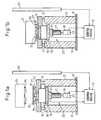
- Figs. 1a and 1b are views illustrating a basic constitution of a die cushion mechanism 20 in a press machine equipped with a control device 10 according to the present invention, and show states where the press machine is opened and closed, respectively.
- two support members 12 are extending in a vertical direction from a base 11, and a bolster 15, in the shape of a flat plate, is arranged at the ends of the support members 12 via dampers 13.
- a die cushion mechanism 20 is provided under the bolster 15.
- the die cushion mechanism 20 includes an elastic element 30 that expands and contracts in the vertical direction relative to the lower surface of the bolster 15, a cushion pad 16 that is incorporated in the press machine and moves in correspondence with the motion of a slide 24 and a servo motor 18 for lifting and lowering the cushion pad 16.
- the elastic element 30 need not be used. In the following description, however, it is presumed that the elastic element 30 is being employed. As shown, the bottom surface of the elastic element 30 is held by the cushion pad 16.
- the elastic element 30 may be an elastic material such as a rubber, a spring or a hydraulic chamber.
- a plurality of cushion pins 31 extend from the top surface of the elastic element 30 and protrude beyond the bolster 15 by passing through the holes of the bolster 15. A material 35 to be worked is supported at the ends of the cushion pins 31.
- the slide 24 supports a first mold 26 used for the press work.
- the slide 24 moves in a direction to approach, or move away from, a second mold 27 supported by the bolster 15 at a speed V required for the press work.
- the slide 24 may be so constituted as to be moved by a servo motor separate from the servo motor 18.
- the cushion pad 16 is arranged in relation to the second mold 27, and is connected to the output shaft of the servo motor 18 via a ball-screw device 17.
- the slide 24 (or the first mold 26), while moving in a direction to close the mold, comes into direct or indirect collision with the cushion pad 16 that is standing at a predetermined position.
- the cushion pad 16 is so constituted as to move together with the slide 24 while applying a predetermined force (pressure) F to the slide 24 from when the mold is closed (molding) until when the mold is opened.
- the cushion pad 16 and the members related thereto are called a die cushion as necessary.
- the cushion pins 31 are further lowered, and the material 35 to be worked is press-worked while being held between the first mold 26 of the slide 24 and the second mold 27 of the bolster 15.
- the bolster 15 is slightly lowered by the slide 24.
- the slide 24 starts rising, and the other members, too, return back to their initial positions to end the press work.
- the control device 10 produces a correlative pressure (i.e., force F) between the cushion pad 16 and the slide 24 by controlling the servo motor 18.
- a force detection unit 21 for detecting this pressure i.e., force F
- a speed detection unit 22 that detects the rotational speed of the servo motor 18 as a speed of the die cushion, too, is connected to the control device 10.
- a position detection unit 25 is arranged neighboring the support member 12, and is connected to the control device 10.
- the position detection unit 25 detects the position of the die cushion mechanism 20 in the vertical direction, particularly detects the position of the cushion pad 16 in the vertical direction and, further, detects the position of the slide 24 in the vertical direction. That is, the position detection unit 25 functions as the die cushion position detecting means and the slide position detecting means. The position detection unit 25 is, further, capable of detecting the distance between the slide 24 and the die cushion.
- the force detection unit 21 may be a known force sensor
- the speed detection unit 22 may be a known encoder
- the position detection unit 25 may be a known linear scale or an encoder (using a rack and a pinion gear).
- control device 10 is equipped with a position control unit 920 and a switch 930 (see Fig. 15 ) which are the same as those of the prior art.
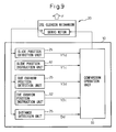
- Fig. 2 is a functional block diagram illustrating the control device for the die cushion mechanism according to the first embodiment of the present invention.
- the control device 10 based on the first embodiment includes a force instruction unit 51 included in a force control unit 940 and for instructing a force Fc to be produced for the die cushion mechanism 20, a force detection unit 21 for detecting a force Fd produced in the die cushion mechanism 20, and a first differentiating circuit 23a and a second differentiating circuit 23b connected to the force detection unit 21.
- the control device 10 further includes a comparison operation unit 95 which compares a force instruction value Fc instructed by the force instruction unit 51 in the force control unit 940, a force detection value Fd detected by the force detection unit 21, a first-order differentiated force detection value Fd' of the force detection value Fd put through first-order differentiation through the first-order differentiating circuit 23a and a second-order differentiated force detection value Fd" of the force detection value Fd put through second-order differentiation through the first-order differentiating circuit 23a and the second-order differentiating circuit 23b, with their respective threshold values or a force value Fd0 detected before the operation that will be described later.
- a comparison operation unit 95 which compares a force instruction value Fc instructed by the force instruction unit 51 in the force control unit 940, a force detection value Fd detected by the force detection unit 21, a first-order differentiated force detection value Fd' of the force detection value Fd put through first-order differentiation through the first-order differentiating circuit 23a and a second-order differentiated force
- the die cushion is, first, operated and controlled by the position control unit 920.
- a collision judgement signal is fed to the switch 930, and the die cushion is changed from being controlled by the position control unit 920 to being controlled by the force control unit 940.
- Figs. 3a to 5 Described below with reference to Figs. 3a to 5 is how to judge the collision of the slide 24 with the die cushion by the control device 10 for the die cushion mechanism 20 according to the first embodiment of the invention.
- Programs (methods) 110 to 230 and programs 240 and 250 for judging the collision illustrated in the flowcharts of the drawings have been stored in advance in the storage unit (not shown) in the control device 10.
- the programs 110 to 230 for judging the collision are repetitively executed when the die cushion mechanism 20 is in operation.
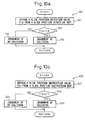
- the force detection value Fd is obtained from the force detection unit 21 (step 111), and the comparison operation unit 95 compares the force detection value Fd with a threshold value L1 (step 113).
- the threshold value L1 and other threshold values that will be described later had been found, in advance, through experiment and stored in the storage unit in the control device 10.
- the force detection value Fd is greater than the threshold value L1
- it is so judged that the slide 24 has collided with the die cushion step 114.
- the force detection value Fd is not greater than the threshold value L1, it is so judged that no collision has taken place (step 115).
- a pre-load value Fd0 is obtained from the force detection unit 21 (step 121).
- the pre-load value Fd0 is a force detection value detected by the force detection unit 21 when the slide 24 is not colliding with the die cushion or, concretely, before the cushion pin 31 comes in contact with the slide 24.
- the comparison operation unit 95 compares the force detection value Fd with the pre-load value Fd0 (step 123).
- the force detection value Fd is greater than the pre-load value Fd0, it is so judged that the slide 24 has collided with the die cushion (step 124).
- the force detection value Fd is not greater than the pre-load value Fd0, it is so judged that no collision has taken place (step 125).
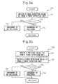
- a force detection value Fd is obtained from the force detection unit 21 (step 131) and is put through first-order differentiation through the first-order differentiating circuit 23a.
- a first-order differentiated force detection value Fd' thus obtained is fed to the comparison operation unit 95 where it is compared with a threshold value L2 (step 133).
- the first-order differentiated force detection value Fd' is greater than the threshold value L2, it is judged that the slide 24 has collided with the die cushion (step 134).
- the first-order differentiated force detection value Fd' is not greater than the threshold value F2, it is judged that no collision has taken place (step 135).
- a force detection value Fd is obtained from the force detection unit 21 (step 141) and is put through second-order differentiation through the first-order differentiating circuit 23a and the second-order differentiating circuit 23b.
- a second-order differentiated force detection value Fd" thus obtained is fed to the comparison operation unit 95 where it is compared with a threshold value L3 (step 143).
- the second-order differentiated force detection value Fd is greater than the threshold value L3, it is judged that the slide 24 has collided with the die cushion (step 144).
- the second-order differentiated force detection value Fd" is not greater than the threshold value L3, it is so judged that no collision has taken place (step 145).
- a force instruction value Fc is obtained from a force instruction unit 51 (step 151).
- the comparison operation unit 95 compares the force detection value Fd with the force instruction value Fc (step 153).
- the force detection value Fd is greater than the force instruction value Fc, it is judged that the slide 24 has collided with the die cushion (step 154).
- the force detection value Fd is not greater than the force instruction value Fc, it is judged that no collision has taken place (step 155).
- the die cushion is changed by the switch 930 from being controlled by the position control unit 920 over to being controlled by the force control unit 940. As a result, a suitable cushion pressure is produced.
- the position control speed instruction value Vcx is not compared with the force control speed instruction value Vcf unlike that of the prior art.
- the cushion pad is being lowered as described above, it becomes difficult to judge the collision based on the comparison of the force control speed instruction value Vcf with the position control speed instruction value Vcx, and the judgement of collision involves a delay.
- the first embodiment makes it possible to judge the collision within a short period of time since it uses neither the force control speed instruction value Vcf nor the position control speed instruction value Vcx. As a result, the first embodiment makes it possible to prevent an increase in the overshooting amount of the force that stems from a delay in the judgement of collision.
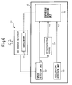
- Fig. 6 is a functional block diagram illustrating the control device for the die cushion mechanism according to a second embodiment of the present invention.
- the control device 10 based on the second embodiment includes a speed detection unit 22 for detecting a speed of the die cushion, a third differentiating circuit 23c connected to the speed detection unit 22, and an acceleration detection unit 29 (not shown in Fig. 1 ) for detecting the acceleration of the die cushion.
- the control device 10 further includes a comparison operation unit 95 which compares a speed detection value Vd of the die cushion detected by the speed detection unit 22, a first-order differentiated speed detection value Vd' of the speed detection value Vd put to the first-order differentiation through the third differentiating circuit 23c and an acceleration detection value Ad of the die cushion detected by the acceleration detection unit 29, with their respective threshold values.
- a speed detection value Vd of the die cushion is obtained from the die cushion speed detection unit 22 (step 161) and is compared with a threshold value L3 in the comparison operation unit 95 (step 163).
- the speed detection value Vd of the die cushion is greater than the threshold value L3, it is so judged that the slide 24 has collided with the die cushion (step 164).
- the speed detection value Vd of the die cushion is not greater than the threshold value L3, it is so judged that no collision has taken place (step 165).
- a speed detection value Vd of the die cushion is obtained from the die cushion speed detection unit 22 (step 171) and is put through first-order differentiation through the third differentiating circuit 23c.
- the first-order differentiated speed detection value Vd' thus obtained is fed to the comparison operation unit 95 where it is compared with a threshold value L4 (step 173).
- the first-order differentiated speed detection value Vd' is greater than the threshold value L4, it is so judged that the slide 24 has collided with the die cushion (step 174).
- the first-order differentiated speed detection value Vd' is not greater than the threshold value L4, it is so judged that no collision has taken place (step 175).
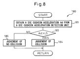
- an acceleration detection value Ad of the die cushion is obtained from the die cushion acceleration detection unit 29 (step 181) and is compared with a threshold value L5 in the comparison operation unit 95 (step 183).
- the acceleration detection value Ad of the die cushion is greater than the threshold value L5, it is so judged that the slide 24 has collided with the die cushion (step 184).
- the acceleration detection value Ad of the die cushion is not greater than the threshold value L5, it is so judged that no collision has taken place (step 185).
- the die cushion is changed by the switch 930 from being controlled by the position control unit 920 over to being controlled by the force control unit 940 like in the case of the first embodiment. As a result, a suitable cushion pressure is produced.
- the position control speed instruction value Vcx is not compared with the force control speed instruction value Vcf, unlike that of the prior art. Namely, the second embodiment makes it possible to judge the collision within a short period of time since it uses neither the force control speed instruction value Vcf nor the position control speed instruction value Vcx. As a result, the second embodiment makes it possible to prevent an increase in the overshooting amount of the force that stems from a delay in the judgement of collision.
- Fig. 9 is a functional block diagram illustrating the control device for the die cushion mechanism according to a third embodiment of the present invention.
- the control device 10 based on the third embodiment includes a slide position detection unit 25 for detecting a position of the slide 24, a slide position instruction unit 61 for instructing the position of the slide 24, a die cushion position detection unit 25 for detecting a position of the die cushion, a die cushion position instruction unit 62 for instructing the position of the die cushion, and a distance detection unit 25 for detecting a distance between the slide 24 and the die cushion.
- the position detection unit 25 also works as the die cushion position detection unit, as the slide position detection unit and as the distance detection unit.
- the control device 10 further includes a comparison operation unit 95 which compares a slide position detection value Y1d detected by the slide position detection unit 25, a slide position instruction value Y1c instructed by the slide position instruction unit 61, a die cushion position detection value Y2d detected by the die cushion position detection unit 25, a die cushion position instruction value Y2c instructed by the die cushion position instruction unit 62, and a distance detection value Dd between the slide and the die cushion detected by the distance detection unit 25, with their respective threshold values.
- a comparison operation unit 95 which compares a slide position detection value Y1d detected by the slide position detection unit 25, a slide position instruction value Y1c instructed by the slide position instruction unit 61, a die cushion position detection value Y2d detected by the die cushion position detection unit 25, a die cushion position instruction value Y2c instructed by the die cushion position instruction unit 62, and a distance detection value Dd between the slide and the die cushion detected by the distance detection unit 25, with their respective threshold values.
- a slide position detection value Y1d is obtained from the slide position detection unit 25 (step 191) and is compared with a threshold value L6 in the comparison operation unit 95 (step 193).
- a threshold value L6 is compared with the comparison operation unit 95 (step 193).
- the slide position detection value Y1d is smaller than the threshold value L6, it is so judged that the slide 24 has collided with the die cushion (step 194).
- the slide position detection value Y1d is not smaller than the threshold value L6, it is so judged that no collision has taken place (step 195).
- a slide position instruction value Y1c is obtained from the slide position instruction unit 61 (step 201) and is compared with a threshold value L7 in the comparison operation unit 95 (step 203).
- the slide position instruction value Y1c is smaller than the threshold value L7, it is so judged that the slide 24 has collided with the die cushion (step 204).
- the slide position instruction value Y1c is not smaller than the threshold value L7, it is so judged that no collision has taken place (step 205).
- a slide position detection value Y1d is obtained from the slide position detection unit 25 (step 211). Then, after a die cushion position detection value Y2d is obtained from the die cushion position detection unit 25 (step 212), the comparison operation unit 95 compares the slide position detection value Y1d with the die cushion position detection value Y2d (step 213). Next, when the slide position detection value Y1d is smaller than or equal to the die cushion position detection value Y2d, it is so judged that the slide 24 has collided with the die cushion (step 214). When the slide position detection value Y1d is not smaller than or equal to the die cushion position detection value Y2d, it is judged that no collision has taken place (step 215).
- the distance may contract between the detected position of the slide 24 and the detected position of the die cushion at the time of collision to instantaneously create a condition "slide position detection value Y1d ⁇ die cushion position detection value Y2d".
- a slide position instruction value Y1c is obtained from the slide position instruction unit 61 (step 221). Then, after a die cushion position instruction value Y2c is obtained from the die cushion position instruction unit 62 (step 222), the comparison operation unit 95 compares the slide position instruction value Y1c with the die cushion position instruction value Y2c (step 223). Next, when the slide position instruction value Y1c is smaller than or equal to the die cushion position instruction value Y2c, it is so judged that the slide 24 has collided with the die cushion (step 224). When the slide position instruction value Y1c is not smaller than or equal to the die cushion position instruction value Y2c, it is judged that no collision has taken place (step 225).
- a distance Dd is obtained from the distance detection unit 25 that detects the distance Dd between the slide and the die cushion (step 231), and is compared with a threshold value L8 by the comparison operation unit 95 (step 233).
- a threshold value L8 is compared with the comparison operation unit 95 (step 233).
- the distance Dd between the slide and the die cushion is smaller than the threshold value L8, it is so judged that the slide 24 has collided with the die cushion (step 234).
- the distance Dd between the slide and the die cushion is not smaller than the threshold value L8, it is judged that no collision has taken place (step 235).
- the die cushion is changed by the switch 930 from being controlled by the position control unit 920 over to being controlled by the force control unit 940 like in the above-mentioned embodiments. As a result, a suitable cushion pressure is produced.
- the position control speed instruction value Vex is not compared with the force control speed instruction value Vcf, unlike that of the prior art. Namely, the third embodiment makes it possible to judge the collision within a short period of time because it uses neither the force control speed instruction value Vcf nor the position control speed instruction value Vcx. As a result, the third embodiment makes it possible to prevent an increase in the overshooting amount of the force that stems from a delay in the judgement of collision.
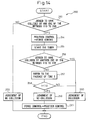
- Fig. 13 is a flowchart of a program illustrating the operation of a system for judging the collision based on the present invention.
- the program 240 shown in Fig. 13 first, there is executed any one of the programs (methods) 110 to 230 for judging the collision (step 241).
- the judgement of collision is rendered, there is executed another method of the programs (methods) 110 to 230 for judging the collision (step 242).
- step 244 the judgement of collision is rendered in the system for judging the collision according to the program 240.
- the system for judging the collision according to the program 240 does not render a judgement of collision (step 245).
- the system for judging the collision shown in Fig. 13 as described above there are executed at least two of the programs (methods) 110 to 230 for judging the collision.
- the system for judging the collision renders the judgement of collision. Therefore, the system for judging the collision illustrated in Fig. 13 enhances the reliability of judgement of collision as compared to the judgement based on any one of the programs (methods) 110 to 230 for judging the collision, and makes it possible to avoid, as much as possible, an occurrence that the press work cannot be executed due to erroneous judgement.
- Fig. 14 is another flowchart illustrating the operation of the system for judging the collision according to the present invention.
- the program 250 shown in Fig. 14 there is, first, executed any one of the programs (methods) 110 to 230 for judging the collision according to the first to third embodiments (step 251).
- the switch 930 changes the position control unit 920 over to the force control unit 940 (step 254). Therefore, the switching operation is carried out more quickly by the switch 930 than in the case of the system for judging the collision shown in Fig. 13 .
- the timer is driven simultaneously with the switching operation by the switch 930 to record the passage of time T after the switching operation (step 255).
- the timer that is not shown, has been incorporated in the control device 10.
- step 257 When the judgement of collision is not rendered at step 256, on the other hand, reference is made to the passage of time T (step 257) to judge whether the passage of time T is shorter than a predetermined value T0 (step 258).
- the passage of time T is from after the end of the method of judging the collision at step 251 until after the end of the method of judging the collision at step 256.
- the passage of time T is shorter than the predetermined period of time T0, it is so judged that the judgement at step 256 was executed within the predetermined period of time T0 after step 251.
- the system for judging the collision described with reference to Figs. 13 and 14 executes two of the programs (methods) 110 to 230 for judging the collision.
- the system for judging the collision may employ a further increased number of programs 110 to 230 for judging the collision to further enhance the reliability of the result of judging the collision.
Landscapes
- Engineering & Computer Science (AREA)
- Mechanical Engineering (AREA)
- Human Computer Interaction (AREA)
- Manufacturing & Machinery (AREA)
- Physics & Mathematics (AREA)
- General Physics & Mathematics (AREA)
- Automation & Control Theory (AREA)
- Shaping Metal By Deep-Drawing, Or The Like (AREA)
- Presses And Accessory Devices Thereof (AREA)
Applications Claiming Priority (2)
| Application Number | Priority Date | Filing Date | Title |
|---|---|---|---|
| JP2005195097A JP2007007716A (ja) | 2005-07-04 | 2005-07-04 | ダイクッション機構の衝突判定装置および衝突判定システム |
| EP06012673A EP1742127A3 (en) | 2005-07-04 | 2006-06-20 | Device for judging collision of a die cushion mechanism and system for judging collision |
Related Parent Applications (1)
| Application Number | Title | Priority Date | Filing Date |
|---|---|---|---|
| EP06012673A Division EP1742127A3 (en) | 2005-07-04 | 2006-06-20 | Device for judging collision of a die cushion mechanism and system for judging collision |
Publications (1)
| Publication Number | Publication Date |
|---|---|
| EP1973019A1 true EP1973019A1 (en) | 2008-09-24 |
Family
ID=36822413
Family Applications (2)
| Application Number | Title | Priority Date | Filing Date |
|---|---|---|---|
| EP08010486A Withdrawn EP1973019A1 (en) | 2005-07-04 | 2006-06-20 | Device for judging collision of a die cushion mechanism and system for judging collision |
| EP06012673A Withdrawn EP1742127A3 (en) | 2005-07-04 | 2006-06-20 | Device for judging collision of a die cushion mechanism and system for judging collision |
Family Applications After (1)
| Application Number | Title | Priority Date | Filing Date |
|---|---|---|---|
| EP06012673A Withdrawn EP1742127A3 (en) | 2005-07-04 | 2006-06-20 | Device for judging collision of a die cushion mechanism and system for judging collision |
Country Status (4)
| Country | Link |
|---|---|
| US (2) | US20070012083A1 (enExample) |
| EP (2) | EP1973019A1 (enExample) |
| JP (1) | JP2007007716A (enExample) |
| CN (2) | CN101261508A (enExample) |
Families Citing this family (9)
| Publication number | Priority date | Publication date | Assignee | Title |
|---|---|---|---|---|
| DE102007005011B4 (de) * | 2007-02-01 | 2012-09-06 | Saeta Gmbh & Co. Kg | Verfahren und Ziehwerkzeug zum Tiefziehen von Rohlingen aus Blechmaterial zu flanschlosen Formlingen |
| JP4595017B2 (ja) | 2009-02-16 | 2010-12-08 | ファナック株式会社 | サーボダイクッションの制御装置 |
| DE112010005277T5 (de) * | 2010-02-17 | 2013-01-24 | Mitsubishi Electric Corporation | Parallelantriebssystem |
| JP6100727B2 (ja) * | 2014-04-09 | 2017-03-22 | ファナック株式会社 | リードスルー機能を有する人協調型産業用ロボット |
| CN112735186A (zh) * | 2020-12-25 | 2021-04-30 | 安徽省安泰科技股份有限公司 | 一种基于物联网的设备安全预警系统及其实施方法 |
| CN114964835A (zh) * | 2021-02-25 | 2022-08-30 | 安川电机(中国)有限公司 | 龙门机构的碰撞检测方法及其装置 |
| CN114964836A (zh) * | 2021-02-25 | 2022-08-30 | 安川电机(中国)有限公司 | 龙门机构的碰撞检测方法及其装置 |
| CN113751739B (zh) * | 2021-08-03 | 2023-02-21 | 南京工大数控科技有限公司 | 一种数控机床智能防碰撞系统 |
| CN116759226B (zh) * | 2023-08-17 | 2023-10-24 | 合肥综合性国家科学中心能源研究院(安徽省能源实验室) | 一种核聚变环向场超导线圈绕制的多自由度导体落模系统 |
Citations (5)
| Publication number | Priority date | Publication date | Assignee | Title |
|---|---|---|---|---|
| US4524582A (en) * | 1983-03-31 | 1985-06-25 | Cincinnati Incorporated | Control system for hydraulic presses |
| US5692404A (en) * | 1993-02-25 | 1997-12-02 | Toyota Jidosha Kabushiki Kaisha | Method of diagnosing pressing machine based on detected physical value as compared with reference |
| US5701811A (en) * | 1994-12-21 | 1997-12-30 | Komatsu Ltd. | Die protection apparatus for a hydraulic press |
| JPH1133799A (ja) * | 1997-07-23 | 1999-02-09 | Komatsu Ltd | 電動プレスの制御方法及び制御装置 |
| US20030116037A1 (en) | 2001-12-21 | 2003-06-26 | Aida Engineering, Ltd. | Press machine |
Family Cites Families (5)
| Publication number | Priority date | Publication date | Assignee | Title |
|---|---|---|---|---|
| JPH0419093A (ja) * | 1990-05-14 | 1992-01-23 | Meidensha Corp | ロボットの衝突検出装置 |
| US5309138A (en) * | 1991-03-19 | 1994-05-03 | Honda Giken Kogyo Kabushiki Kaisha | Vehicle collision detecting method employing an acceleration sensor |
| JP3169247B2 (ja) * | 1991-12-03 | 2001-05-21 | 株式会社石井工作研究所 | プレス機械の加圧力自動制御方法とその装置 |
| US5952589A (en) * | 1996-01-11 | 1999-09-14 | Systems, Machines, Automation Components Corporation | Soft landing method for probe assembly |
| DE19812133A1 (de) * | 1998-03-20 | 1999-09-23 | Baltec Maschinenbau Ag | Verfahren zum Steuern, Überwachen und Überprüfen eines Umformvorganges einer Umformmaschine, insbesondere Nietmaschine |
-
2005
- 2005-07-04 JP JP2005195097A patent/JP2007007716A/ja not_active Withdrawn
-
2006
- 2006-06-20 EP EP08010486A patent/EP1973019A1/en not_active Withdrawn
- 2006-06-20 EP EP06012673A patent/EP1742127A3/en not_active Withdrawn
- 2006-06-30 US US11/477,804 patent/US20070012083A1/en not_active Abandoned
- 2006-07-03 CN CNA2008100055174A patent/CN101261508A/zh active Pending
- 2006-07-03 CN CNB2006101005455A patent/CN100391642C/zh not_active Expired - Fee Related
-
2008
- 2008-06-05 US US12/155,525 patent/US20080245121A1/en not_active Abandoned
Patent Citations (5)
| Publication number | Priority date | Publication date | Assignee | Title |
|---|---|---|---|---|
| US4524582A (en) * | 1983-03-31 | 1985-06-25 | Cincinnati Incorporated | Control system for hydraulic presses |
| US5692404A (en) * | 1993-02-25 | 1997-12-02 | Toyota Jidosha Kabushiki Kaisha | Method of diagnosing pressing machine based on detected physical value as compared with reference |
| US5701811A (en) * | 1994-12-21 | 1997-12-30 | Komatsu Ltd. | Die protection apparatus for a hydraulic press |
| JPH1133799A (ja) * | 1997-07-23 | 1999-02-09 | Komatsu Ltd | 電動プレスの制御方法及び制御装置 |
| US20030116037A1 (en) | 2001-12-21 | 2003-06-26 | Aida Engineering, Ltd. | Press machine |
Also Published As
| Publication number | Publication date |
|---|---|
| CN100391642C (zh) | 2008-06-04 |
| CN101261508A (zh) | 2008-09-10 |
| US20070012083A1 (en) | 2007-01-18 |
| JP2007007716A (ja) | 2007-01-18 |
| US20080245121A1 (en) | 2008-10-09 |
| EP1742127A3 (en) | 2007-01-24 |
| CN1891370A (zh) | 2007-01-10 |
| EP1742127A2 (en) | 2007-01-10 |
Similar Documents
| Publication | Publication Date | Title |
|---|---|---|
| US20080245121A1 (en) | Device for judging collision of a die cushion mechanism and system for judging collision | |
| JP2006122944A (ja) | ダイクッション制御装置 | |
| US7923956B2 (en) | Control device for servo die cushion | |
| EP1743718B1 (en) | Control system for servo die cushion | |
| US6520075B1 (en) | Double action hydraulic press | |
| JP4741310B2 (ja) | プレス機械及びその制御装置 | |
| EP1741499B1 (en) | Force control device for a servo die cushion without force detector | |
| US7041242B2 (en) | Mold-clamping control method for injection molding machine | |
| EP3434438B1 (en) | Injection molding machine | |
| JP4712475B2 (ja) | ダイクッション機構並びにその制御装置及び制御方法 | |
| JP2008168353A (ja) | ダイクッション機構の衝突判定装置および衝突判定システム | |
| US7631528B2 (en) | Die cushion mechanism, and apparatus and method for controlling the same | |
| JP2007098422A (ja) | ダイクッション機構の制御装置 | |
| JPH10216997A (ja) | 直動型プレスの絞り成形加工制御装置及びその方法 | |
| JP4824463B2 (ja) | ダイクッション機構の制御装置 | |
| JP5428948B2 (ja) | 油圧ダイクッション装置及びその制御方法 | |
| JP4610635B2 (ja) | ダイクッション機構並びにその制御装置及び制御方法 | |
| US7685860B2 (en) | Control device for press machine | |
| CA2510553C (en) | Clamping unit for an injection-molding device | |
| JP2007111703A (ja) | ダイクッション機構の制御装置 | |
| CN103648674A (zh) | 模具缓冲控制装置 | |
| JP4237780B2 (ja) | 電動射出成形機の型開装置及び電動射出成形機の型開方法 | |
| CN216760631U (zh) | 整形注塑模具 | |
| JP2010284657A (ja) | アクティブダンパーの制御装置及び方法 | |
| CN118418385A (zh) | 注塑设备及注射平衡控制方法 |
Legal Events
| Date | Code | Title | Description |
|---|---|---|---|
| PUAI | Public reference made under article 153(3) epc to a published international application that has entered the european phase |
Free format text: ORIGINAL CODE: 0009012 |
|
| AC | Divisional application: reference to earlier application |
Ref document number: 1742127 Country of ref document: EP Kind code of ref document: P |
|
| AK | Designated contracting states |
Kind code of ref document: A1 Designated state(s): AT BE BG CH CY CZ DE DK EE ES FI FR GB GR HU IE IS IT LI LT LU LV MC NL PL PT RO SE SI SK TR |
|
| AX | Request for extension of the european patent |
Extension state: AL BA HR MK RS |
|
| 17P | Request for examination filed |
Effective date: 20090225 |
|
| 17Q | First examination report despatched |
Effective date: 20090423 |
|
| AKX | Designation fees paid |
Designated state(s): DE |
|
| STAA | Information on the status of an ep patent application or granted ep patent |
Free format text: STATUS: THE APPLICATION IS DEEMED TO BE WITHDRAWN |
|
| 18D | Application deemed to be withdrawn |
Effective date: 20090904 |