EP1972835A2 - System und Verfahren zur Steuerung eines Automatikgetriebes - Google Patents
System und Verfahren zur Steuerung eines Automatikgetriebes Download PDFInfo
- Publication number
- EP1972835A2 EP1972835A2 EP08001190A EP08001190A EP1972835A2 EP 1972835 A2 EP1972835 A2 EP 1972835A2 EP 08001190 A EP08001190 A EP 08001190A EP 08001190 A EP08001190 A EP 08001190A EP 1972835 A2 EP1972835 A2 EP 1972835A2
- Authority
- EP
- European Patent Office
- Prior art keywords
- sleeve
- gear
- free rotatable
- rotatable gear
- balk
- Prior art date
- Legal status (The legal status is an assumption and is not a legal conclusion. Google has not performed a legal analysis and makes no representation as to the accuracy of the status listed.)
- Granted
Links
- 230000005540 biological transmission Effects 0.000 title claims description 62
- 238000000034 method Methods 0.000 title claims description 16
- 230000033001 locomotion Effects 0.000 claims abstract description 26
- 230000007935 neutral effect Effects 0.000 claims abstract description 22
- 230000002401 inhibitory effect Effects 0.000 claims description 21
- 238000012546 transfer Methods 0.000 claims description 10
- 230000000694 effects Effects 0.000 claims description 7
- 238000012545 processing Methods 0.000 description 78
- 230000007246 mechanism Effects 0.000 description 60
- 230000005764 inhibitory process Effects 0.000 description 20
- 239000003921 oil Substances 0.000 description 14
- 239000000446 fuel Substances 0.000 description 10
- 230000008859 change Effects 0.000 description 4
- 230000001360 synchronised effect Effects 0.000 description 4
- 238000004891 communication Methods 0.000 description 3
- 238000010276 construction Methods 0.000 description 3
- 230000007423 decrease Effects 0.000 description 3
- 230000002950 deficient Effects 0.000 description 3
- 238000010586 diagram Methods 0.000 description 3
- 230000003292 diminished effect Effects 0.000 description 3
- 238000002347 injection Methods 0.000 description 3
- 239000007924 injection Substances 0.000 description 3
- 230000009467 reduction Effects 0.000 description 3
- 230000004044 response Effects 0.000 description 3
- 230000035939 shock Effects 0.000 description 3
- 230000003247 decreasing effect Effects 0.000 description 2
- 230000006866 deterioration Effects 0.000 description 2
- 238000011161 development Methods 0.000 description 2
- 239000010687 lubricating oil Substances 0.000 description 2
- VNWKTOKETHGBQD-UHFFFAOYSA-N methane Chemical compound C VNWKTOKETHGBQD-UHFFFAOYSA-N 0.000 description 2
- 230000004048 modification Effects 0.000 description 2
- 238000012986 modification Methods 0.000 description 2
- 230000008439 repair process Effects 0.000 description 2
- 230000001133 acceleration Effects 0.000 description 1
- 230000009471 action Effects 0.000 description 1
- 238000013459 approach Methods 0.000 description 1
- 230000003111 delayed effect Effects 0.000 description 1
- 230000000994 depressogenic effect Effects 0.000 description 1
- 238000001514 detection method Methods 0.000 description 1
- 230000003467 diminishing effect Effects 0.000 description 1
- 230000009977 dual effect Effects 0.000 description 1
- 239000000314 lubricant Substances 0.000 description 1
- 238000005461 lubrication Methods 0.000 description 1
- 230000014759 maintenance of location Effects 0.000 description 1
- 239000003345 natural gas Substances 0.000 description 1
Images






Classifications
-
- F—MECHANICAL ENGINEERING; LIGHTING; HEATING; WEAPONS; BLASTING
- F16—ENGINEERING ELEMENTS AND UNITS; GENERAL MEASURES FOR PRODUCING AND MAINTAINING EFFECTIVE FUNCTIONING OF MACHINES OR INSTALLATIONS; THERMAL INSULATION IN GENERAL
- F16H—GEARING
- F16H61/00—Control functions within control units of change-speed- or reversing-gearings for conveying rotary motion ; Control of exclusively fluid gearing, friction gearing, gearings with endless flexible members or other particular types of gearing
- F16H61/26—Generation or transmission of movements for final actuating mechanisms
- F16H61/28—Generation or transmission of movements for final actuating mechanisms with at least one movement of the final actuating mechanism being caused by a non-mechanical force, e.g. power-assisted
- F16H61/2807—Generation or transmission of movements for final actuating mechanisms with at least one movement of the final actuating mechanism being caused by a non-mechanical force, e.g. power-assisted using electric control signals for shift actuators, e.g. electro-hydraulic control therefor
-
- F—MECHANICAL ENGINEERING; LIGHTING; HEATING; WEAPONS; BLASTING
- F16—ENGINEERING ELEMENTS AND UNITS; GENERAL MEASURES FOR PRODUCING AND MAINTAINING EFFECTIVE FUNCTIONING OF MACHINES OR INSTALLATIONS; THERMAL INSULATION IN GENERAL
- F16H—GEARING
- F16H61/00—Control functions within control units of change-speed- or reversing-gearings for conveying rotary motion ; Control of exclusively fluid gearing, friction gearing, gearings with endless flexible members or other particular types of gearing
- F16H61/12—Detecting malfunction or potential malfunction, e.g. fail safe ; Circumventing or fixing failures
-
- F—MECHANICAL ENGINEERING; LIGHTING; HEATING; WEAPONS; BLASTING
- F16—ENGINEERING ELEMENTS AND UNITS; GENERAL MEASURES FOR PRODUCING AND MAINTAINING EFFECTIVE FUNCTIONING OF MACHINES OR INSTALLATIONS; THERMAL INSULATION IN GENERAL
- F16H—GEARING
- F16H59/00—Control inputs to control units of change-speed- or reversing-gearings for conveying rotary motion
- F16H59/68—Inputs being a function of gearing status
- F16H2059/6807—Status of gear-change operation, e.g. clutch fully engaged
-
- F—MECHANICAL ENGINEERING; LIGHTING; HEATING; WEAPONS; BLASTING
- F16—ENGINEERING ELEMENTS AND UNITS; GENERAL MEASURES FOR PRODUCING AND MAINTAINING EFFECTIVE FUNCTIONING OF MACHINES OR INSTALLATIONS; THERMAL INSULATION IN GENERAL
- F16H—GEARING
- F16H61/00—Control functions within control units of change-speed- or reversing-gearings for conveying rotary motion ; Control of exclusively fluid gearing, friction gearing, gearings with endless flexible members or other particular types of gearing
- F16H61/12—Detecting malfunction or potential malfunction, e.g. fail safe ; Circumventing or fixing failures
- F16H2061/1208—Detecting malfunction or potential malfunction, e.g. fail safe ; Circumventing or fixing failures with diagnostic check cycles; Monitoring of failures
- F16H2061/1212—Plausibility checks; Counting means for repeated failures
-
- F—MECHANICAL ENGINEERING; LIGHTING; HEATING; WEAPONS; BLASTING
- F16—ENGINEERING ELEMENTS AND UNITS; GENERAL MEASURES FOR PRODUCING AND MAINTAINING EFFECTIVE FUNCTIONING OF MACHINES OR INSTALLATIONS; THERMAL INSULATION IN GENERAL
- F16H—GEARING
- F16H61/00—Control functions within control units of change-speed- or reversing-gearings for conveying rotary motion ; Control of exclusively fluid gearing, friction gearing, gearings with endless flexible members or other particular types of gearing
- F16H61/12—Detecting malfunction or potential malfunction, e.g. fail safe ; Circumventing or fixing failures
- F16H2061/1224—Adapting to failures or work around with other constraints, e.g. circumvention by avoiding use of failed parts
-
- F—MECHANICAL ENGINEERING; LIGHTING; HEATING; WEAPONS; BLASTING
- F16—ENGINEERING ELEMENTS AND UNITS; GENERAL MEASURES FOR PRODUCING AND MAINTAINING EFFECTIVE FUNCTIONING OF MACHINES OR INSTALLATIONS; THERMAL INSULATION IN GENERAL
- F16H—GEARING
- F16H61/00—Control functions within control units of change-speed- or reversing-gearings for conveying rotary motion ; Control of exclusively fluid gearing, friction gearing, gearings with endless flexible members or other particular types of gearing
- F16H61/12—Detecting malfunction or potential malfunction, e.g. fail safe ; Circumventing or fixing failures
- F16H2061/1256—Detecting malfunction or potential malfunction, e.g. fail safe ; Circumventing or fixing failures characterised by the parts or units where malfunctioning was assumed or detected
- F16H2061/1276—Detecting malfunction or potential malfunction, e.g. fail safe ; Circumventing or fixing failures characterised by the parts or units where malfunctioning was assumed or detected the failing part is a friction device, e.g. clutches or brakes
-
- F—MECHANICAL ENGINEERING; LIGHTING; HEATING; WEAPONS; BLASTING
- F16—ENGINEERING ELEMENTS AND UNITS; GENERAL MEASURES FOR PRODUCING AND MAINTAINING EFFECTIVE FUNCTIONING OF MACHINES OR INSTALLATIONS; THERMAL INSULATION IN GENERAL
- F16H—GEARING
- F16H61/00—Control functions within control units of change-speed- or reversing-gearings for conveying rotary motion ; Control of exclusively fluid gearing, friction gearing, gearings with endless flexible members or other particular types of gearing
- F16H61/26—Generation or transmission of movements for final actuating mechanisms
- F16H61/28—Generation or transmission of movements for final actuating mechanisms with at least one movement of the final actuating mechanism being caused by a non-mechanical force, e.g. power-assisted
- F16H2061/2823—Controlling actuator force way characteristic, i.e. controlling force or movement depending on the actuator position, e.g. for adapting force to synchronisation and engagement of gear clutch
-
- Y—GENERAL TAGGING OF NEW TECHNOLOGICAL DEVELOPMENTS; GENERAL TAGGING OF CROSS-SECTIONAL TECHNOLOGIES SPANNING OVER SEVERAL SECTIONS OF THE IPC; TECHNICAL SUBJECTS COVERED BY FORMER USPC CROSS-REFERENCE ART COLLECTIONS [XRACs] AND DIGESTS
- Y10—TECHNICAL SUBJECTS COVERED BY FORMER USPC
- Y10T—TECHNICAL SUBJECTS COVERED BY FORMER US CLASSIFICATION
- Y10T74/00—Machine element or mechanism
- Y10T74/19—Gearing
- Y10T74/19219—Interchangeably locked
- Y10T74/19284—Meshing assisters
Definitions
- the present invention relates to a control system and method for an automatic transmission. Particularly, the present invention resides in a control system and method for an automated MT (MT: Manual Transmission) which results from automating clutch/shift operations of a conventional manual transmission.
- MT Manual Transmission
- AMT Automated Manual Transmission
- a control system for an automatic transmission having an input shaft adapted to receive torque from a driving force source and rotate thereby, an output shaft for output of torque to a drive shaft of a vehicle, a plurality of gears adapted to rotate in synchronism with the input shaft and/or the output shaft, a plurality of free rotatable gears meshing with the gears, a plurality of sleeves adapted to rotate in synchronism with the input shaft and/or the output shaft and slidable axially, and a balk ring disposed between the free rotatable gears and the sleeves, wherein the balk ring is pushed against any of the free rotatable gears by movement of any of the sleeves, thereby synchronizing rotation of the sleeve with that of the free rotatable gear, and the sleeve and the free rotatable gear are brought into mesh with each other by further movement of the sleeve to attain
- Fig. 1 is a system configuration diagram showing an automobile control system according to an embodiment of the present invention.
- an engine 7 as a driving force source, an engine speed sensor (not shown), an electronic controlled throttle (not shown) for adjusting engine torque, and a fuel injector (not shown) for injecting fuel in an amount matching the amount of intake air.
- the torque of the engine 7 can be controlled highly accurately by adjusting the amount of intake air, amount of fuel and ignition timing with use of an engine control unit 101.
- the fuel injector there is known an intake port injection type wherein fuel is injected to an intake port or a direct injection type wherein fuel is injected directly into a cylinder.
- a driving range a range depending on engine torque and engine speed
- the driving force source may be not only a gasoline engine but also a diesel engine, a natural gas engine, or an electric motor.
- a clutch 8 and a transmission 200 is connected to the engine 7.
- the clutch 8 is composed of an input disc 8a and an output disc 8b.
- the transmission 200 is composed of an input shaft 41 connected to the cltuch 8 and output shaft 42 connected to an driving system of the vehicle. By engaging and disengaging the input disc 8a and the output disc 8b it is possible to transmit or cut off the torque of the engine 7 to an input shaft 41 of the transmission 200.
- the clutch 8 there generally is employed a dry type single plate clutch, provided there may be used all other clutches, including a wet type multiple disc clutch and an electromagnetic clutch.
- an input shaft clutch actuator 111 adapted to operate using a motor. By adjusting the pushing force (input shaft clutch torque) it is possible to make and break the transmission of the output of the engine 7 to the input shaft 41.
- a first driving gear 1, a second driving gear 2, a third driving gear 3, a fourth driving gear 4, a fifth driving gear 5 and a sixth driving gear 6, as free rotatable gears, are mounted on the input shaft 41. These free rotatable gears are mounted so as to be restrained their axial movement relative to the input shaft 41 but rotatable relative to the input shaft 41.
- As input shaft revolution detecting means there is provided an input shaft revolution sensor 31 for detecting the number of revolutions of the input shaft 41.
- a first driven gear 11, a second driven gear 12, a third driven gear 13, a fourth driven gear 14, a fifth driven gear 15 and a sixth driven gear 16 are mounted on an output shaft 42 of the transmission. These driven gears are fixed to the output shaft 42.
- output shaft revolution detecting means there is provided an output shaft revolution sensor 32 for detecting the number of revolutions of the output shaft 42.
- a oil temperature censor 33 is provided in the transmission 200 for censing the temperature of the lubricant oil lubricationg the components in the transmission 200. The output of the oil temperature censor 33 is send to the motor control unit 104 and used for controlling the drive of the specific gear shift range.
- the free rotatable gears are mounted on the input shaft and fixed gears are provided on the output shaft
- this arrangement may be modified such that the free rotatable gears are provided on the output shaft and the fixed gears provided on the input shaft.
- sleeves are mounted on the shaft on which the free rotatable gears are provided.
- the first driving gear 1 and the first driven gear 11 are in mesh with each other and so are the second driving gear 2 and the second driven gear 12, the third driving gear 3 and the third driven gear 13, the fourth driving gear 4 and the fourth driven gear 14, the fifth driving gear 5 and the fifth driven gear 15, and the sixth driving gear 6 and the sixth driven gear 16.
- a first synchromesh mechanism 21 for bringing the first driving gear 1 or the fourth driving gear 4 into engagement with the input shaft 41 is disposed between the first driving gear 1 and the fourth driving gear 4.
- Rotational torque inputted to the input shaft 41 is transmitted via the first synchromesh mechanism 21 to the first driving gear 1, the first driven gear 11 and the output shaft 42 or to the fourth driving gear 4, the fourth driven gear 14 and the output shaft 42.
- a second synchromesh mechanism 22 for bringing the second driving gear 2 or the fifth driving gear 5 into engagement with the input shaft 41 is disposed between the second driving gear 2 and the fifth driving gear 5. Therefore, rotational torque inputted to the input shaft 41 is transmitted via the second synchromesh mechanism 22 to the second driving gear 2, the second driven gear 12 and the output shaft 42 or to the fifth driving gear 5, the fifth driven gear 15 and the output shaft 42.
- a third synchromesh mechanism 23 for bringing the third driving gear 3 or the sixth driving gear 6 into engagement with the input shaft 41 is disposed between the third driving gear 3 and the sixth driving gear 6. Therefore, rotational torque inputted to the input shaft 41 is transmitted via the third synchromesh mechanism 23 to the third driving gear 3, the third driven gear 13 and the output shaft 42 or to the six driving gear, the sixth driven gear 16 and the output shaft 42.
- any one of the first, second and third synchromesh mechanisms 21, 22, 23 be moved axially of the input shaft 41 and be brought into engagement with any one of the first, second, third, fourth, fifth and sixth driving gears 1, 2 , 3 , 4 , 5 , 6 .
- a shift A actuator 112 is operated for moving the first synchromesh mechanism 21.
- a shift B actuator 113 is operated for moving the second synchromesh mechanism 22 and a shift C actuator 114 is operated for moving the third synchromesh mechanism 23.
- an electric current of a motor (not shown) provided in the input shaft actuator 111 is controlled by a motor control unit 104, thereby controlling transfer torque of the clutch 8.
- the input shaft clutch actuator 111 is made up of the motor and a reduction mechanism or a mechanical part for converting the rotational motion of the motor into a linear motion. For example, it is constituted by a worm gear or a ball screw.
- a motor actuator is used as the input shaft clutch actuator 111, there may be used an actuator operated hydraulically.
- pushing loads for operating the first, second and third synchromesh mechanisms 21, 22, 23, as well as the positions thereof, can be controlled by controlling the electric currents of motors (not shown) provided in the shift A actuator 112, shift B actuator 113 and shift C actuator 114 with use of the motor control unit 104.
- the shift A actuator 112, shift B actuator 113 and shift C actuator 114 are each constituted by a motor and a reduction mechanism or a mechanical part for converting the rotational motion of the motor into a linear motion. For example, it is constituted by a gear and an arm, or a ball screw.
- the shift A actuator 112 By controlling the shift A actuator 112 to control the first synchromeshmechanism 21, the first synchromeshmechanism 21 and the first driving gear 1 come into mesh with each other, providing a first shift range.
- the shift A actuator 112 By controlling the shift A actuator 112 to control the first synchromesh mechanism 21, the first synchromesh mechanism 21 and the fourth driving gear 4 come into mesh with each other, providing a fourth shift range.
- the second synchromesh mechanism 22 and the second driving gear 2 come into mesh with each other, providing a second shift range.
- the shift B actuator 113 By controlling the shift B actuator 113 to control the second synchromesh mechanism 22, the second synchromesh mechanism 22 and the fifth driving gear 5 come into mesh with each other, providing a fifth shift range.
- the third synchromesh mechanism 23 and the third driving gear 3 come into mesh with each other, providing a third shift range.
- the shift C actuator 114 By controlling the shift C actuator 114 to control the third synchromesh mechanism 23, the third synchromesh mechanism 23 and the sixth driving gear 6 come into mesh with each other, providing a sixth shift range.
- a manual control unit 105 is provided in the system as an switching means for the manual operation of a driver.
- the output of the manual control unit 105 is send to the motor control unit 104.
- the manual control unit 105 can skip over the shift range of the inhibited gear.
- the torque of the engine 7 is controlled with high accuracy by controlling the amount of intake air, the amount of fuel and ignition timing with use of the engine control unit 101.
- the motor control unit 104, the manual control unit 105 and the engine control unit 101 are controlled by a power train control unit 100.
- the power train control unit 100, engine control unit 101, the manual control unit 105 and motor control unit 104 transmit and receive information to and from one another through communication means 103.
- Fig. 2 is a pertially cutout cross sectional view showing the construction of a synchromeshmechanism. More specifically, Fig. 2 is an extracted and enlarged sectional view of the portions of the first synchromesh mechanism 21, input shaft 41 and first driving gear 1 which are shown in Fig. 1 .
- a sleeve 21a is splined to a hub 21c which rotates together with the input shaft 41.
- a key 21b moves together with the sleeve 21a and an end face thereof pushes a balk ring 21d against a cone portion of the first driving gear 1 which is a free rotatable gear.
- friction occurs on a cone surface between the balk ring 21d and the first driving gear 1 to effect the transfer of torque, so that the rotation of the first driving gear 1 gradually approaches the rotation of the sleeve 21a.
- the balk ring 21d becomes rotatable and no longer obstructs the movement of the sleeve 21a.
- the sleeve 21a passes the balk ring 21d and comes into complete mesh with a gear dog 1a of the first driving gear 1. Shift is now completed.
- synchromesh mechanisms used in this embodiment are an inertial lock key type, there also may be used any of various other types, including a pin type and a servo type.
- Fig. 3 there is shown an input/output signal relation among the power train control unit 100, engine control unit 101 and motor control unit 104.
- the power train control unit 100 is constituted as a control unit having an input portion 100i, an output portion 100o and a computer 100c.
- the engine control unit 101 is constituted as a control unit having an input portion 101i, an output portion 101o and a computer 101c.
- the motor control unit 104 is also constituted as a control unit having an input portion 104i, an output portion 104o and a computer 104c.
- an engine torque command value TTe is transmitted from the power train control unit 100 to the engine control unit 101, which in turn controls the amount of intake air, the amount of fuel and ignition timing for the engine 7.
- detection means for detecting engine torque as input torque to the transmission.
- the number of revolutions Ne of the engine 7 and engine torque T4 generated by the engine 7 are detected by the engine control unit 101 and are transmitted to the power train control unit 100 through the communication means 103.
- the engine torque detecting means there may be used a torque sensor or estimation means using engine parameters such as, for example, the injection pulse width of an injector, internal pressure of an intake pipe and engine speed.
- Shift A motor target torque TMsftA, shift B motor target torque TMsftB, shift C motor target torque TMsftC, and input shaft clutch motor target torque TMsta are transmitted from the power train control unit 100 to the motor control unit 104, which in turn controls the motor current in the shift A actuator 112 so as to attain the shift A motor target torque TMsftA and performs pushing, engagement and release of the first synchromesh mechanism 21.
- the motor control unit 104 controls the motor currents in the shift B actuator 113 and the shift C actuator 114 so as to attain the shift B motor target torque TMsftB and the shift C motor target torque TMsftC and performs pushing, engagement and release of the second and third synchromesh mechanisms 22, 23.
- the motor control unit 104 controls the motor current in the input shaft clutch actuator 111 and performs engagement and release of the input disc 8a and the output disc 8b of the clutch 8 to attain the clutch motor target torque TMsta.
- the motor control unit 104 detects a shift A position signal rpSFTA indicating the stroke of the first synchromesh mechanism 21, a shift B position signal rpSFTB indicating the stroke of the second synchromesh mechanism 22, a shift C position signal rpSFTC indicating the stroke of the third synchromesh mechanism 23, and a position signal rpSTA indicting the stroke of the input shaft clutch 8, and transmits the detected signals to the power train control unit 100.
- Input shaft revolutions Ni and output shaft revolutions No are inputted to the power train control unit 100 from the input shaft revolution sensor 31 and the output shaft revolution sensor 32, respectively. Further, a range position signal RngPos indicating a shift lever position such as P range, R range, N range, or D range, an accelerator pedal depression quantity Aps, and an ON/OFF signal Brk provided from a brake switch which signal detects whether the brake is depressed or not, are inputted to the power train control unit 100.
- a range position signal RngPos indicating a shift lever position such as P range, R range, N range, or D range, an accelerator pedal depression quantity Aps, and an ON/OFF signal Brk provided from a brake switch which signal detects whether the brake is depressed or not, are inputted to the power train control unit 100.
- the power train control unit 100 judges that the driver has the intention of starting and acceleration, while when the driver depresses the brake pedal, the power train control unit 100 judges that the driver has the intention of deceleration and stop. Then, in such a manner as to realize the driver's intention, the power train control unit 100 sets the engine torque command value TTe, shift A motor target torque TMsftA, shift B motor target torque TMsftB, shift C motor target torque TMsftC, and input shaft clutch motor target torque TMsta.
- the power train control unit 100 sets a target shift range on the basis of vehicle speed Vsp calculated from the output shaft revolutions No and the accelerator pedal depression quantity Aps. Then, for execution of a shift operation to the set shift range, the power train control unit 100 sets the engine torque command value TTe, shift A motor target torque TMsftA, shift B motor target torque TMsftB, shift C motor target torque TMsftC, and input shaft clutch motor target torque TMsta.
- Fig. 4 is a flow chart showing the contents of control performed by the automatic transmission control system according to the present invention.
- the following control contents are programmed in the computer 100c of the power train control unit 100 and are executed repeatedly with a predetermined cycle.
- the processing of the following steps 401 to 411 are executed by the power train control unit 100.
- step 401 parameters are read, then in step 402, any one of the first, second and third synchromesh mechanisms 21, 22, 23 is selected in accordance with a target shift range and a check is made to see if a control of clamping the sleeve of the selected synchromesh mechanism to a free rotatable gear has been started or not. If the clamping control has been started, the processing flow advances to step 403 (balk abutment determining means), while if the clamping control has not been started, the processing is ended. Next, in step 403, it is determined whether the sleeve in operation is a fixed state or not near the balk ring, then the processing flow advances to step 404.
- step 403 is made on the basis of whether the state in which the stroke position signal of the selected synchromeshmechanism out of shift A position signal rpSFTA, shift B position signal rpSFTB and shift C position signal rpSFTC as stroke position signals of the first, second and third synchromesh mechanisms 21, 22, 23 lies within a predetermined range near the balk ring has continued or not for a predetermined time. If in step 404 it is determined that the sleeve in operation is in a fixed state or not near the balk ring, the processing flow advances to step 408 (load increasing control), in which a pushing load increasing control for the sleeve is performed.
- load increasing control load increasing control
- step S409 balk abutment determining means
- step S410 balk abutment determining means
- step S410 a check is made to see if the sleeve in operation is in a fixed state or not near the balk ring
- step S410 If it is determined in step S410 that the sleeve in operation is in a fixed state near the balk ring, the processing flow advances to step 411 (retry control means), in which there is performed a control of one returning the sleeve to its neutral position and reclamping it to a free rotatable gear. If it is determined in step 410 that the sleeve in operation is not in a fixed state near the balk ring, the processing flow advances to step 405 (gear dog abutment determination means).
- step 404 determines whether the sleeve in operation is in a fixed state near the balk ring. If it is determined in step 404 that the sleeve in operation is not in a fixed state near the balk ring, the processing flow advances to step 405 (gear dog abutment determination). In step 405, a check is made to see if the sleeve in operation is in a fixed state or not near the gear dog of the free rotatable gear, followed by advance to step 406.
- step 405 is made on the basis of whether the state in which the stroke position signal of the selected synchromesh mechanism out of shift A position signal rpSFTA, shift B position signal rpSFTB and shift C position signal rpSFTC as stroke position signals of the first, second and third synchromesh mechanisms 21, 22, 23 lies within a predetermined range near the gear dog of the free rotatable gear has continued or not for a predetermined time. If it is determined in step 406 that the sleeve in operation is in a fixed state near the gear dog of the free rotatable gear, the processing flow advances to step 411 (retry control), in which there is performed a control of once returning the sleeve to its neutral position and reclamping it to the free rotatable gear.
- retry control a control of once returning the sleeve to its neutral position and reclamping it to the free rotatable gear.
- step 406 If it is determined in step 406 that the sleeve in operation is not in a fixed state near the gear dog of the free rotatable gear, the processing flow advances to step 407, in which it is determined whether the clamping of the sleeve in operation to the free rotatable gear has been completed or not in accordance with the stroke position signal of the selected synchromesh mechanism. If it is determined in step 407 that the clamping of the sleeve to the free rotatable gear has not been completed yet, the processing flow shifts to step 403, while if it is determined that the clamping of the sleeve to the free rotatable gear has been completed, the processing is ended.
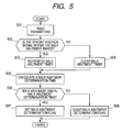
- Fig. 5 is a flow chart showing processing contents of steps 403 and 409 (balk abutment determination) in Fig. 4 .
- step 501 parameters are read, then in step 502 it is determined whether a stroke position signal lies within a balk abutment range or not.
- the balk abutment range indicates a range from where the moving sleeve 21a comes into abutment against the balk ring 21d up to where the further moving sleeve 21a has got over the balk ring 21d. If it is determined that the stroke position signal lies within the balk abutment range, the processing flow advances to step 503, in which there is performed a balk abutment timer increment processing. On the other hand, if it is determined that the stroke position signal does not lie within the balk abutment range, the processing flow shifts to step 504, in which there is performed a balk abutment time clear processing.
- step 505 a balk abutment determination time is calculated for determining whether the sleeve in operation is fixed to the balk ring or not, followed by advance to step 506. Since the state of each synchromesh mechanism changes depending on the number of times of repetition of the retry control, the transmission oil temperature and shift range, it is preferable that the balk abutment determination time be adjusted according to the number of times of the retry control, the transmission oil temperature and shift range. Then, in step 506, it is determined whether the time set in the balk abutment timer is longer than the balk abutment determination time or not.
- step 506 If it is determined in step 506 that the time set in the balk abutment timer is longer than the balk abutment determination time, the processing flow advances to step 507, in which Balk Abutment Determination Flag is set and the processing is ended. On the other hand, if it is determined in step 506 that the time set in the balk abutment timer is shorter than the balk abutment determination time, the processing flow shifts to step 508, in which Balk Abutment Determination Flag is cleared and the processing is ended.
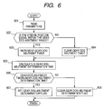
- Fig. 6 is a flow chart showing processing contents of step 405 (gear dog abutment determination) in Fig. 4 .
- step 601 parameters are read, then in step 602 it is determined whether a stroke position signal lies within a gear dog abutment range or not.
- the gear dog abutment range indicates a range from contact of the sleeve 21a with the gear dog 1a until engagement of the sleeve 21a with the gear dog 1a. If it is determined that the stroke position signal lies within the gear dog abutment range, the processing flow advances to step 603, in which there is performed a gear dog abutment time increment processing. On the other hand, if it is determined that the stroke position signal does not lie within the gear dog abutment range, the processing flow shifts to step 604, in which there is performed a balk abutment timer clear processing.
- step 605 a gear dog abutment determination time is calculated for determining whether the sleeve in operation is in a fixed state to the gear dog of a free rotatable gear, followed by advance to step 606. Since the state of each synchromesh mechanism changes depending on the number of times of repetition of the re-clamping control (retry control), the oil temperature and shift range, it is preferable that the gear dog abutment determination time be adjusted according to the number of times of the retry control, the oil temperature and shift range. Then, in step 606, it is determined whether the time set in the gear dog abutment timer is longer than the gear dog abutment determination time or not.
- step 606 If it is determined in step 606 that the time set in the gear dog abutment timer is longer than the gear dog abutment determination time, the processing flow advances to step 607, in which Gear Dog Abutment Determination Flag is set and the processing is ended. On other hand, if it is determined in step 606 that the time set in the gear dog abutment timer is shorter than the gear dog abutment determination time, the processing flow shifts to step 608, in which Gear Dog Abutment Determination Flag is cleared and the processing is ended.
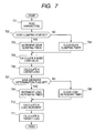
- Fig. 7 is a flow chart showing the contents of processing performed for clamping a sleeve to a free rotatable gear.
- the processing of steps 707 to 711 in the same figure correspond to the processing of step 408 (load increasing means) in Fig. 4 .
- step 701 parameters are read, then in step 702 there is selected any one of the first, second and third synchromesh mechanisms 21, 22, 23 in accordance with a target shift range and it is determined whether a control for clamping the sleeve of the selected synchromesh mechanism to a free rotatable gear has been started or not. If this control has been started, the processing flow advances to step 703, in which there is performed a gear clamping timer increment processing. On the other hand, if the control in question has not been started yet, the processing shifts to step 704, in which there is performed a gear clamping time clear processing. Next, in step 705, there is calculated a basic value of a sleeve pushing load which becomes necessary in the clamping control.
- the basic value of the pushing load is preferably set in accordance with the time set in a gear clamping timer which is calculated in steps 703 and 704 so as to cushion a collision shock against the balk ring in an initial stage of clamping.
- a limiter load which is a limit value of the sleeve pushing load in the clamping control, followed by advance to step 707. It is preferable that the limiter load be set in accordance with a stroke signal so as to cushion a collision shock at the time of clamping of the sleeve to the gear dog.
- step 707 it is determined whether Balk Abutment Determination Flag is set or not. If the answer is affirmative, the processing flow advances to step 708, in which there is performed a load increase timer increment processing. On the other hand, if Balk Abutment Determination Flag is cleared, the processing flow advances to step 709, in which there is performed a load increase timer clear processing. Then, in step 710, an increment of the pushing load is calculated as a countermeasure to the case where the sleeve in operation is fixed to the balk ring due to a lack of synchronizing power.
- step 711 there is calculated an added value of both basic load value and load increment and there is selected either the added value or the limiter load whichever is the smaller, thereby calculating a target load for the sleeve.
- Fig. 8 is a flow chart showing the contents of processing of step 411 (retry processing) in Fig. 4 .
- step 801 parameters are read, then in step 802 it is determined whether Gear Dog Abutment Determination Flag is set or not or whether Balk Abutment Determination Flag is set or not after execution of the load increase control. If it is determined that either of the two flags is set, the processing flow advances to step 803 , in which there is performed a processing for setting Retry Execution Flag. On the other hand, if it is determined that both flags referred to above are cleared, the processing flow advances to step 804, in which there is performed a processing for clearing Retry Execution Flag.
- step 805 it is determined whether the control for clamping the sleeve of the selected synchromesh mechanism to the free rotatable gear is under execution or not and whether Retry Execution Flag is set or not. If it is determined that the said control is not under execution or that Retry Execution Flag is cleared, the processing flow advances to step S807, in which Retry Release Flag is cleared and the processing is ended. On the other hand, if it is determined that the control for clamping the sleeve to the free rotatable gear is under execution and that Retry Execution Flag is set, the processing flow advances to step 806, in which Retry Release Flag is set and the processing flow advances to step 808.
- step 808 the sleeve clamping control for the free rotatable gear is stopped and there is executed a gear release control for once returning the sleeve in operation to its neutral position, followed by advance to step 809.
- the gear release control it is necessary that the sleeve in operation be returned accurately up to its neutral position. Therefore, it is preferable that the stroke position signal be fed back to calculate the pushing load.
- step 809 it is determined whether Retry Release Flag has changed from Clear to Set state or not. If the answer is affirmative, the processing flow advances to step 810, in which there is performed an increment processing for a retry counter and the processing is ended. On the other hand, if it is determined that Retry Release Flag has not changed from Clear to Set state, the processing is ended without performing the retry counter increment processing.
- the retry counter clear processing may be done upon completion of the clamping of the sleeve in operation to the free rotatable gear or may be done upon start-up or end of the power train control unit so that there may remain the history of retry count within the driving cycle concerned (during the period from ON to OFF of the ignition switch). Further, in order to let the history of retry count remain from the time of shipping up to the present, there may be adopted a modification so as to store the history in a backup RAM (Random Access Memory) or EE-PROM (Electronically Erasable and Programmable Read Only Memory) mounted on the power train control unit 100 without performing the retry count clear processing.
- a backup RAM Random Access Memory
- EE-PROM Electrically Erasable and Programmable Read Only Memory
- the shift range concerned can be inhibited with use of specific gear shift range inhibiting means when the retry count exceeds a predetermined count, whereby it is possible to prevent damage of the transmission. Besides, by letting the history of retry count remain, a failed, or defective, part can be detected in a selling store or a repair shop.
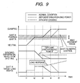
- Fig. 9 is a time chart used in case of performing a load increase control on the basis of balk abutment determination.
- time is plotted along the axis of abscissa, while the shift A position rpSFTA as a stroke signal of the first synchromesh mechanism 21, differential revolution
- the shift A target load TFSFTA is decreased gradually by the limiter load described above in connection with Fig. 7 in order to cushion the collision shock of the sleeve against the gear dog, then at time t4 the shift position A rpSFTA becomes the clamping position, whereby the sleeve clamping control for the free rotatable gear is completed.
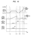
- Fig. 10 is a time chart used in case of performing the retry control in response to balk abutment determination after execution of the pushing load increasing control in response to the balk abutment determination.
- Fig. 10 time is plotted along the axis of abscissa, while the shift A position rpSFTA as a stroke signal of the first synchromesh mechanism 21, a balk abutment timer TMRBKNG, Retry Execution Flag fRTRYEXE and Retry Release Flag fSOFRTRY are plotted in this order from above along the axis of ordinate.
- the sleeve can be clamped to the free rotatable gear positively by once returning the sleeve to its neutral position and performing a re-clamping operation of the sleeve for the free rotatable gear.
- the sleeve is once returned to its neutral position, it becomes possible to feed oil to between the balk ring and the gear dog cone.
- oil is scraped up by rotation of a gear to effect lubrication.
- the amount of lubricating oil may be increased at the time of sticking of the balk ring.
- the sleeve is in a fixed state near the balk ring despite the differential revolution being synchronized. Therefore, by adding the information on differential revolution to the result of the balk abutment determination it is possible to determine a lack of synchronizing power or sticking of the balk ring. For example, when the value of
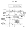
- Fig. 11 is a time chart used when performing the retry control on the basis of gear dog abutment determination.
- time is plotted along the axis of abscissa, while the shift A position rpSFTA as a stroke signal of the first synchromesh mechanism 21, the differential revolution
- a gear dog abutment timer (not shown) is incremented on the basis of the gear dog abutment determination described above in connection with Fig. 6 .
- Gear Dog Abutment Determination Flag (not shown) is set and a shift is made to the retry control.
- the operation of the retry control is the same as that described above in connection with Fig. 10 .
- Gear Dog Abutment Determination Flag (not shown) is set at time t5 and a shift is made to the retry control.
- gear Dog Abutment Determination Flag (not shown) is set at time t5 and a shift is made to the retry control.
- the clamping can be effected upon synchronization of the differential revolution
- the sleeve in the case of desynchronization, the sleeve once stays near the balk ring, but in the case of asynchronous meshing the sleeve does not stay near the balk ring and reaches near the gear dog, so it is also possible to make distinction between desynchronization and asynchronous meshing in accordance with a change (differential value) of the stroke position signal.
- the balk ring is deteriorated in the case of asynchronous meshing and therefore it is preferable that the use of the free rotatable gear concerned be inhibited at once by specific gear shift range inhibiting means to be described later to prevent damage of the transmission.
- Fig. 12 is a flow chart showing the contents of control performed by specific gear shift range inhibiting means.
- step 1202 it is determined whether the retry count calculated by the retry count calculating means which has been described above in connection with Fig. 8 is larger than a predetermined value or not. If it is determined that the retry count is larger than the predetermined value, the processing flow advances to step 1211, in which it is determined whether the target gear position is the first shift range or not. On the other hand, if it is determined in step 1202 that the retry count is smaller than the predetermined value, the processing is ended. If it is determined in step 1211 that the target gear position is the first shift range, the processing flow advances to step 1221, in which there is performed a processing for inhibiting the use of the first shift gear.
- step 1211 If it is determined in step 1211 that the target gear position is not the first shift range, the processing flow advances to step 1212, in which it is determined whether the target gear position is the second shift range or not. If it is determined in step 1212 that the target gear position is the second shift range, the processing flow advances to step 1222, in which there is performed a processing for inhibiting the use of the second shift gear. Such determinations and processing are conducted up to the sixth shift range and then the processing in question is ended.
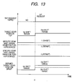
- the layout number Fig. 13 is a time chart used when performing a shifting operation in accordance with a switch operation of the driver in a state in which the use of the free rotatable gear of the second shift range is inhibited by the specific gear shift range inhibiting means.
- Fig. 13 time is plotted along the axis of abscissa, while a tap request TAPRQ (Up request: 0 ⁇ +1, Down request: 0 ⁇ -1) as a switch operation signal, a target gear position TGP, Specific Gear Shift Range Inhibition Flag [1] (second shift range). Specific Gear Shift Range Inhibition Flag [2] (third shift range), and a defined target gear position GPNXT, are plotted in this order from above along the axis of ordinate.
- the driver's switch operation signal corresponds to a shift request made by a paddle switch attached to a steering wheel and a shift request made by a floor switch attached to a shift lever for shifting operations to P, R, N and D ranges.
- the second synchromesh mechanism 22 is selected in accordance with the value of the defined target gear position GPNXT and there is performed a control for clamping the sleeve to the second driving gear 2 which is a free rotatable gear of the second shift range.
- calculation of the defined target gear position GPNXT is performed after making reference to the value of Specific Gear Shift Range Inhibition Flag [2] (third shift range).
- the defined target gear position GPNXT is updated to the third shift range.
- the third synchromesh mechanism 23 is selected in accordance with the value of the defined target gear position GPNXT and there is performed a control for clamping the sleeve to the third driving gear 3 which is a free rotatable gear of the third shift range.
- the present invention is applicable to all of systems which performs switching of the shift range with use of a synchromesh mechanism, such as, for example, an automated MT system having a friction type clutch in one of shift ranges, and a generally well-known twin clutch automated MT (DCT: Dual Clutch Transmission).
- a synchromesh mechanism such as, for example, an automated MT system having a friction type clutch in one of shift ranges, and a generally well-known twin clutch automated MT (DCT: Dual Clutch Transmission).
- the pushing load for the sleeve is increased, while if the sleeve is fixed near the free rotatable gear, there is performed a control of once returning the sleeve to its neutral position and re-clamping it to the free rotatable gear .
Landscapes
- Engineering & Computer Science (AREA)
- General Engineering & Computer Science (AREA)
- Mechanical Engineering (AREA)
- Control Of Transmission Device (AREA)
- Gear-Shifting Mechanisms (AREA)
Applications Claiming Priority (1)
| Application Number | Priority Date | Filing Date | Title |
|---|---|---|---|
| JP2007069744A JP4341687B2 (ja) | 2007-03-19 | 2007-03-19 | 自動変速機の制御装置および制御方法 |
Publications (3)
| Publication Number | Publication Date |
|---|---|
| EP1972835A2 true EP1972835A2 (de) | 2008-09-24 |
| EP1972835A3 EP1972835A3 (de) | 2012-05-30 |
| EP1972835B1 EP1972835B1 (de) | 2014-04-09 |
Family
ID=39467158
Family Applications (1)
| Application Number | Title | Priority Date | Filing Date |
|---|---|---|---|
| EP08001190.1A Ceased EP1972835B1 (de) | 2007-03-19 | 2008-01-23 | System und Verfahren zur Steuerung eines Automatikgetriebes |
Country Status (3)
| Country | Link |
|---|---|
| US (1) | US7735388B2 (de) |
| EP (1) | EP1972835B1 (de) |
| JP (1) | JP4341687B2 (de) |
Cited By (1)
| Publication number | Priority date | Publication date | Assignee | Title |
|---|---|---|---|---|
| EP3155300B1 (de) | 2014-06-16 | 2017-12-27 | Volvo Truck Corporation | Verfahren zur steuerung eines aktuators eines fahrzeuggetriebes |
Families Citing this family (23)
| Publication number | Priority date | Publication date | Assignee | Title |
|---|---|---|---|---|
| DE102008045536A1 (de) * | 2008-09-03 | 2010-03-04 | Robert Bosch Gmbh | Verfahren zum Wechseln von Gangstufen und Getriebeanordnung |
| US8560192B2 (en) | 2010-04-15 | 2013-10-15 | GM Global Technology Operations LLC | Control system and method for shift fork position in dual clutch transmissions |
| US8844393B2 (en) * | 2010-04-15 | 2014-09-30 | GM Global Technology Operations LLC | Fork position and synchronization control in a dual clutch transmission using pressure control solenoids |
| US8504267B2 (en) | 2010-04-15 | 2013-08-06 | GM Global Technology Operations LLC | Control system and method for synchronization control in dual clutch transmissions |
| CN102221081B (zh) * | 2010-04-15 | 2015-05-27 | 通用汽车环球科技运作公司 | 使用压力控制螺线管的拨叉位置和同步的控制 |
| CN102959210B (zh) * | 2010-06-29 | 2015-08-26 | 本田技研工业株式会社 | 双离合变速器 |
| KR101241217B1 (ko) * | 2010-11-30 | 2013-03-13 | 현대자동차주식회사 | 자동차의 수동 변속기 |
| KR101865968B1 (ko) * | 2012-12-17 | 2018-06-08 | 현대자동차주식회사 | Amt 차량의 변속장치 제어방법 |
| JP6070380B2 (ja) * | 2013-04-16 | 2017-02-01 | アイシン精機株式会社 | 車両用自動変速機の自動変速装置 |
| JP6344659B2 (ja) * | 2013-06-05 | 2018-06-20 | 株式会社エフ・シー・シー | 車両用動力伝達システム |
| KR101538228B1 (ko) * | 2013-11-04 | 2015-07-20 | 엘에스엠트론 주식회사 | 기어 변속 시스템 및 그것의 기어 변속 방법 |
| DE102014019127B4 (de) * | 2014-12-19 | 2016-11-03 | Audi Ag | Verfahren zum Betreiben einer Getriebeeinrichtung für ein Kraftfahrzeug sowie entsprechende Getriebeeinrichtung |
| JP6565008B2 (ja) * | 2015-05-22 | 2019-08-28 | ジヤトコ株式会社 | 自動変速機 |
| KR101714192B1 (ko) * | 2015-08-12 | 2017-03-08 | 현대자동차주식회사 | 클러치 버스트 방지 방법 |
| JP6443695B2 (ja) * | 2016-09-07 | 2018-12-26 | トヨタ自動車株式会社 | 車両の走行制御装置 |
| JP6600320B2 (ja) * | 2017-01-31 | 2019-10-30 | 本田技研工業株式会社 | 制御装置および制御システム |
| KR102053431B1 (ko) * | 2017-12-06 | 2019-12-06 | 현대자동차(주) | Dct차량의 기어치합 제어방법 |
| JP2019183896A (ja) * | 2018-04-04 | 2019-10-24 | トヨタ自動車株式会社 | 車両用動力伝達装置の制御装置 |
| CN109707841B (zh) * | 2019-01-03 | 2020-07-28 | 海马汽车有限公司 | 故障清除方法及装置 |
| JP7099410B2 (ja) * | 2019-06-28 | 2022-07-12 | トヨタ自動車株式会社 | 同期噛合機構の制御装置 |
| JP7388308B2 (ja) * | 2020-07-22 | 2023-11-29 | スズキ株式会社 | 変速装置の制御装置 |
| KR102456925B1 (ko) * | 2021-04-15 | 2022-10-21 | 주식회사 현대케피코 | 시프트 바이 와이어 시스템의 모터 고착 진단 및 해소 방법, 그리고 그 장치 |
| JP7849213B2 (ja) * | 2022-04-21 | 2026-04-21 | ヤンマーホールディングス株式会社 | 変速装置、作業車両及び制御装置 |
Citations (1)
| Publication number | Priority date | Publication date | Assignee | Title |
|---|---|---|---|---|
| JPH1182710A (ja) | 1997-09-13 | 1999-03-26 | Honda Motor Co Ltd | 電動式変速装置の変速制御方法 |
Family Cites Families (13)
| Publication number | Priority date | Publication date | Assignee | Title |
|---|---|---|---|---|
| DE19526273C2 (de) * | 1995-07-19 | 1999-12-09 | Ford Werke Ag | Automatisch schaltbares Vorgelege-Wechselgetriebe, insbesondere für Kraftfahrzeuge |
| IT1293853B1 (it) * | 1997-06-25 | 1999-03-10 | Magneti Marelli Spa | Metodo e dispositivo di controllo di un gruppo di trasmissione di un veicolo. |
| JPH1122816A (ja) * | 1997-06-30 | 1999-01-26 | Aisin Seiki Co Ltd | シンクロメッシュ式トランスミッションの変速制御装置 |
| JP4447070B2 (ja) * | 1999-05-25 | 2010-04-07 | アイシン・エーアイ株式会社 | 変速機のシフト制御装置 |
| JP2002071005A (ja) * | 2000-08-31 | 2002-03-08 | Aisin Ai Co Ltd | 同期噛合式変速機における変速制御装置 |
| JP4776764B2 (ja) * | 2000-10-03 | 2011-09-21 | アイシン・エーアイ株式会社 | 同期噛合式変速機の制御装置 |
| KR100869183B1 (ko) * | 2000-10-20 | 2008-11-18 | 루크 라멜렌 운트 쿠플룽스바우 베타일리궁스 카게 | 기어박스를 가진 자동차와 자동차의 이용방법 |
| JP4502103B2 (ja) * | 2002-03-27 | 2010-07-14 | スズキ株式会社 | 自動変速機 |
| JP2004011695A (ja) * | 2002-06-04 | 2004-01-15 | Mitsubishi Electric Corp | 同期噛合式自動変速機装置 |
| DE10237245B4 (de) * | 2002-08-13 | 2007-10-18 | Zf Friedrichshafen Ag | Verfahren zur Gangüberwachung für ein Automatgetriebe eines Kraftfahrzeuges |
| US6883394B2 (en) * | 2002-10-15 | 2005-04-26 | Borgwarner, Inc. | Method for controlling the positioning of the synchronizers of a dual clutch transmission |
| JP3984237B2 (ja) * | 2004-04-20 | 2007-10-03 | 本田技研工業株式会社 | アクチュエータの制御装置 |
| FR2891337B1 (fr) * | 2005-09-26 | 2008-12-19 | Peugeot Citroen Automobiles Sa | Boite de vitesses comprenant un actionneur pourvu d'un capteur d'effort |
-
2007
- 2007-03-19 JP JP2007069744A patent/JP4341687B2/ja not_active Expired - Fee Related
-
2008
- 2008-01-23 EP EP08001190.1A patent/EP1972835B1/de not_active Ceased
- 2008-01-24 US US12/019,187 patent/US7735388B2/en active Active
Patent Citations (1)
| Publication number | Priority date | Publication date | Assignee | Title |
|---|---|---|---|---|
| JPH1182710A (ja) | 1997-09-13 | 1999-03-26 | Honda Motor Co Ltd | 電動式変速装置の変速制御方法 |
Cited By (1)
| Publication number | Priority date | Publication date | Assignee | Title |
|---|---|---|---|---|
| EP3155300B1 (de) | 2014-06-16 | 2017-12-27 | Volvo Truck Corporation | Verfahren zur steuerung eines aktuators eines fahrzeuggetriebes |
Also Published As
| Publication number | Publication date |
|---|---|
| US20080234105A1 (en) | 2008-09-25 |
| JP4341687B2 (ja) | 2009-10-07 |
| US7735388B2 (en) | 2010-06-15 |
| EP1972835A3 (de) | 2012-05-30 |
| EP1972835B1 (de) | 2014-04-09 |
| JP2008232200A (ja) | 2008-10-02 |
Similar Documents
| Publication | Publication Date | Title |
|---|---|---|
| EP1972835B1 (de) | System und Verfahren zur Steuerung eines Automatikgetriebes | |
| KR100314604B1 (ko) | 전자적으로개량된파워트레인의기어비변속시간을감소시키는장치및방법 | |
| US5847272A (en) | Function testing device for an actuator system such as a automatic friction clutch used with a motor vehicle gearbox | |
| EP2416029B1 (de) | Fahrzeugleistungsgetriebe-Steuervorrichtung | |
| EP2689978B1 (de) | Kupplungssteuervorrichtung für ein hybridfahrzeug | |
| EP1164310A1 (de) | Zahnradautomatikgetriebe und kraftfahrzeug mit solchem getriebe | |
| EP2653754B1 (de) | Steuerungsvorrichtung für ein doppelkupplungsgetriebe und steuerverfahren für ein doppelkupplungsgetriebe | |
| EP1837560A2 (de) | Automatisiertes Handschaltgetriebe und Verfahren zu seiner Steuerung | |
| US8768589B2 (en) | Control device for dual clutch transmission and control method for dual clutch transmission | |
| US5517411A (en) | Neutral attainment control system/method for controlling shifting in vehicular automated mechanical transmission systems | |
| EP1826445A2 (de) | Steuervorrichtung und Steuerverfahren für eine automatische Fahrzeugkupplung | |
| US8038574B2 (en) | Apparatus and method for controlling automatic transmission | |
| US8041489B2 (en) | Method for controlling a transmission during acceleration from idle | |
| JP5275262B2 (ja) | 自動変速機の制御装置および制御方法 | |
| US20140235405A1 (en) | Vehicle drive system | |
| JP5835573B2 (ja) | 自動変速機のクラッチ制御装置 | |
| US7306544B2 (en) | Automatic transmission, control apparatus and control system | |
| US7252622B2 (en) | Transmission, and control system and control method for the transmission | |
| US6698302B2 (en) | Method of keeping track of the operating position of an actuator in an automated gear-shift transmission | |
| JP2005530111A (ja) | 自動変速システムにおける過誤ニュートラルの検出方法 | |
| JP5030634B2 (ja) | クラッチ制御装置 | |
| JP2009041602A (ja) | 自動変速機の制御装置及び制御方法 | |
| US8463516B2 (en) | Starter release | |
| JP5210926B2 (ja) | 自動変速機の制御方法および制御装置 | |
| JP2009014041A (ja) | 自動車の制御方法及び制御装置 |
Legal Events
| Date | Code | Title | Description |
|---|---|---|---|
| PUAI | Public reference made under article 153(3) epc to a published international application that has entered the european phase |
Free format text: ORIGINAL CODE: 0009012 |
|
| 17P | Request for examination filed |
Effective date: 20080123 |
|
| AK | Designated contracting states |
Kind code of ref document: A2 Designated state(s): AT BE BG CH CY CZ DE DK EE ES FI FR GB GR HR HU IE IS IT LI LT LU LV MC MT NL NO PL PT RO SE SI SK TR |
|
| AX | Request for extension of the european patent |
Extension state: AL BA MK RS |
|
| RIC1 | Information provided on ipc code assigned before grant |
Ipc: F16H 61/28 20060101AFI20111025BHEP Ipc: F16H 61/12 20100101ALN20111025BHEP |
|
| PUAL | Search report despatched |
Free format text: ORIGINAL CODE: 0009013 |
|
| AK | Designated contracting states |
Kind code of ref document: A3 Designated state(s): AT BE BG CH CY CZ DE DK EE ES FI FR GB GR HR HU IE IS IT LI LT LU LV MC MT NL NO PL PT RO SE SI SK TR |
|
| AX | Request for extension of the european patent |
Extension state: AL BA MK RS |
|
| RIC1 | Information provided on ipc code assigned before grant |
Ipc: F16H 61/12 20100101ALN20120113BHEP Ipc: F16H 61/28 20060101AFI20120113BHEP |
|
| PUAF | Information related to the publication of a search report (a3 document) modified or deleted |
Free format text: ORIGINAL CODE: 0009199SEPU |
|
| RIC1 | Information provided on ipc code assigned before grant |
Ipc: F16H 61/28 20060101AFI20120319BHEP Ipc: F16H 61/12 20100101ALN20120319BHEP |
|
| PUAL | Search report despatched |
Free format text: ORIGINAL CODE: 0009013 |
|
| D17D | Deferred search report published (deleted) | ||
| 17Q | First examination report despatched |
Effective date: 20120426 |
|
| AK | Designated contracting states |
Kind code of ref document: A3 Designated state(s): AT BE BG CH CY CZ DE DK EE ES FI FR GB GR HR HU IE IS IT LI LT LU LV MC MT NL NO PL PT RO SE SI SK TR |
|
| AX | Request for extension of the european patent |
Extension state: AL BA MK RS |
|
| AKX | Designation fees paid |
Designated state(s): DE FR |
|
| RIC1 | Information provided on ipc code assigned before grant |
Ipc: F16H 61/28 20060101AFI20130814BHEP Ipc: F16H 61/12 20100101ALN20130814BHEP |
|
| GRAP | Despatch of communication of intention to grant a patent |
Free format text: ORIGINAL CODE: EPIDOSNIGR1 |
|
| INTG | Intention to grant announced |
Effective date: 20130923 |
|
| GRAS | Grant fee paid |
Free format text: ORIGINAL CODE: EPIDOSNIGR3 |
|
| GRAA | (expected) grant |
Free format text: ORIGINAL CODE: 0009210 |
|
| AK | Designated contracting states |
Kind code of ref document: B1 Designated state(s): DE FR |
|
| REG | Reference to a national code |
Ref country code: DE Ref legal event code: R096 Ref document number: 602008031339 Country of ref document: DE Effective date: 20140515 |
|
| REG | Reference to a national code |
Ref country code: DE Ref legal event code: R097 Ref document number: 602008031339 Country of ref document: DE |
|
| PLBE | No opposition filed within time limit |
Free format text: ORIGINAL CODE: 0009261 |
|
| STAA | Information on the status of an ep patent application or granted ep patent |
Free format text: STATUS: NO OPPOSITION FILED WITHIN TIME LIMIT |
|
| 26N | No opposition filed |
Effective date: 20150112 |
|
| REG | Reference to a national code |
Ref country code: DE Ref legal event code: R097 Ref document number: 602008031339 Country of ref document: DE Effective date: 20150112 |
|
| REG | Reference to a national code |
Ref country code: FR Ref legal event code: PLFP Year of fee payment: 9 |
|
| REG | Reference to a national code |
Ref country code: FR Ref legal event code: PLFP Year of fee payment: 10 |
|
| REG | Reference to a national code |
Ref country code: FR Ref legal event code: PLFP Year of fee payment: 11 |
|
| REG | Reference to a national code |
Ref country code: DE Ref legal event code: R081 Ref document number: 602008031339 Country of ref document: DE Owner name: HITACHI ASTEMO, LTD., HITACHINAKA-SHI, JP Free format text: FORMER OWNER: HITACHI AUTOMOTIVE SYSTEMS, LTD., HITACHINAKA-SHI, IBARAKI, JP Ref country code: DE Ref legal event code: R081 Ref document number: 602008031339 Country of ref document: DE Owner name: HITACHI ASTEMO, LTD., HITACHINAKA-SHI, JP Free format text: FORMER OWNER: HITACHI, LTD., TOKYO, JP |
|
| PGFP | Annual fee paid to national office [announced via postgrant information from national office to epo] |
Ref country code: FR Payment date: 20211217 Year of fee payment: 15 |
|
| PGFP | Annual fee paid to national office [announced via postgrant information from national office to epo] |
Ref country code: DE Payment date: 20211130 Year of fee payment: 15 |
|
| REG | Reference to a national code |
Ref country code: DE Ref legal event code: R119 Ref document number: 602008031339 Country of ref document: DE |
|
| PG25 | Lapsed in a contracting state [announced via postgrant information from national office to epo] |
Ref country code: DE Free format text: LAPSE BECAUSE OF NON-PAYMENT OF DUE FEES Effective date: 20230801 |
|
| PG25 | Lapsed in a contracting state [announced via postgrant information from national office to epo] |
Ref country code: FR Free format text: LAPSE BECAUSE OF NON-PAYMENT OF DUE FEES Effective date: 20230131 |