EP1972191B2 - Moissonneuse agricole - Google Patents
Moissonneuse agricole Download PDFInfo
- Publication number
- EP1972191B2 EP1972191B2 EP07123612.9A EP07123612A EP1972191B2 EP 1972191 B2 EP1972191 B2 EP 1972191B2 EP 07123612 A EP07123612 A EP 07123612A EP 1972191 B2 EP1972191 B2 EP 1972191B2
- Authority
- EP
- European Patent Office
- Prior art keywords
- guide plate
- harvesting machine
- agricultural harvesting
- closed
- chopping drum
- Prior art date
- Legal status (The legal status is an assumption and is not a legal conclusion. Google has not performed a legal analysis and makes no representation as to the accuracy of the status listed.)
- Active
Links
Images

Classifications
-
- A—HUMAN NECESSITIES
- A01—AGRICULTURE; FORESTRY; ANIMAL HUSBANDRY; HUNTING; TRAPPING; FISHING
- A01D—HARVESTING; MOWING
- A01D43/00—Mowers combined with apparatus performing additional operations while mowing
- A01D43/08—Mowers combined with apparatus performing additional operations while mowing with means for cutting up the mown crop, e.g. forage harvesters
- A01D43/086—Mowers combined with apparatus performing additional operations while mowing with means for cutting up the mown crop, e.g. forage harvesters and means for collecting, gathering or loading mown material
-
- A—HUMAN NECESSITIES
- A01—AGRICULTURE; FORESTRY; ANIMAL HUSBANDRY; HUNTING; TRAPPING; FISHING
- A01D—HARVESTING; MOWING
- A01D75/00—Accessories for harvesters or mowers
- A01D75/18—Safety devices for parts of the machines
- A01D75/187—Removing foreign objects
Definitions
- the invention relates to an agricultural harvesting machine according to the preamble of claim 1.
- the object underlying the invention is to provide a device within the Erntegut asschachts an agricultural harvester, which eliminates the above-mentioned problems in the prior art and the elimination of blockages or deposits of crop in the Erntegut aspectschacht in a particularly simple manner and allows no longer interruptions of the harvesting operation requires.
- the baffle extends over the entire bottom side of the Erntegut asschachtes in the area between the cutterhead and the subsequent Nachzerklein ceremoniess issued, so that the largest possible outlet opening for falling out of Erntegutablagerache is present.
- the pivot axis for pivoting the baffle at its upper end so that when clogging in the ascending trained Erntegut asschacht gravity due in the lower region of the conveyor chaff accumulating crop can fall out on shortest path in the open position of the baffle from the Erntegut overallschacht ,
- the baffle plate for pivoting comprises a pivoting mechanism designed as a gear system
- a time-consuming loosening of screw fixings is no longer necessary, so that a longer-lasting interruption of the harvesting operation can be prevented by the transmission system is essentially formed by at least one end about a holding device with the baffle of Erntegut asschachtes rotatably connected gear member which other end is rotatably connected via a further holding device to the frame, the waste of the baffle can be achieved by the closed in the open position and vice versa in a structurally simple manner.
- the at least one gear member is designed as a telescopic actuator that is designed in the simplest case as a hydraulic motor or as an electric and / or electronic linear motor, so that when clogging rapid swiveling from the closed to the open position can be achieved
- At least one sensor is mounted at least one point within the cutterhead housing and the sensor is operable as a structure-borne sound receiver wherein the pivoting of the baffle from the open to the closed position takes place due to the sensor signal generated by the sensor, foreign objects registered by the sensor can pass through the outlet opening of the baffle located in the open position fall out and thus greater damage to the subsequent processing organs can be prevented.
- At least one sensor for detecting the torque is arranged at least on the cutterhead and / or on the subsequent processing devices, wherein when a predefined torque is exceeded, the pivoting of the guide plate from the closed to the open position, so that ensured is that possibly resulting from overloading of the work organs resulting crop jams can be detected early or prevented by the crop then before the crop hopper can clogged over the open baffle can fall out.
- the pivoting is done manually by the operator or automatically by means of an evaluation and control device, preferably within the forage harvester assigned to a control unit for operating the pivoting mechanism is provided so that the operator at any time a manual pivoting of the baffle from the closed to the open Position and vice versa in order to be able to react quickly to any blockages in the crop conveyor shaft at any time,
- FIG. 1 shows an executed as a self-propelled forage harvester 1 agricultural harvester 2 in side view and sectional view. This is based on a frame 3, which is supported by front and rear wheels 4, 5.
- the operation of the forage harvester 1 is carried out by the operator 6 via an operating unit 7 from the driver's cab 8, from which the forage harvester 1 is assigned to the front Attachment 9 is visible, which receives crop 10 during operation of the forage harvester 1, cuts and feeds it to the downstream intake and pre-press rollers 11, 12.
- the intake and pre-compression rollers 10, 11 lead the crop 9 of the downstream and rotating, with knives 13 occupied chopper drum 14, which comminuted the crop 10 on a counter-blade 15, the shredded crop 10 is then passed to a Nachzerklein réelles owned 16 before it from the Nachbeschieun Trentsorgan 17 is assumed, the task of Nachzerklein réelles owned 16 is to hit the maize grains in the harvest of maize plants, the Nachzerklein réelles owned 16 can therefore be completely omitted, as far as a, striking the crop 10 - as for grass, for example - is not required.
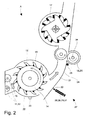
- Fig. 2 now shows in enlarged sectional view the in Fig. 1 A marked region A, the crop flow in the direction of arrow, a chopper drum 14 mounted in a chipper drum housing 19, a Nachzerklein ceremoniess owned 16 in the form of conditioning rollers 20 and a Nachbevantungsorgan 17.
- the conditioning rollers 20 pass the chopped crop 10 to the Nachbevantungsorgan 17 to from there about the horizontally and vertically adjustable in Fig, 1 shown
- the transfer device 18 associated transport device promoted become.
- the cutterhead housing 19 has a bottom plate 22, which adjoins above a pivotable about the pivot axis 23 baffle 24, which is located in the bottom region in the crop conveyor shaft 21 extends over the entire surface between the chopper drum 14 and the post-shredding device 16, in particular when problematic crop 10 or excessively high Erntegutmengen be included, it may overload the chopper drum 14 and the subsequent processing members 16, 17, 20 come, so then an optimal onward transport of the crop 10 is no longer guaranteed and consequently blockages on the one hand in the subsequent processing members 16, 17, 20 but also in Erntegut asschacht 21 may occur according to the invention is now b oden general in Erntegut asschacht 21 in the area between the cutterhead and the subsequent Nachzerklein ceremoniess observed 16 a about a horizontal pivot axis 23 from a closed to an open position pivotable baffle 24 is provided.
- Fig. 2 shows the baffle in a downwardly pivoted about the pivot axis 23, an outlet opening 25 revealing position.
- a particularly expedient embodiment is obtained if, as shown in the embodiment, in the bottom middle of the guide plate 24 formed as a transmission system 26 with the frame 3 of the forage harvester 1 (not shown) in connection standing pivoting mechanism 27 for pivoting the baffle 24 of a closed in an open position is provided
- the transmission system 26 has a designed as a hydraulic cylinder 28 telescopic actuator 29, so that the baffle 24 in a structurally simple way as quickly as possible from the closed in the open position and vice versa is pivoted.
- the transmission system 26 has a telescoping actuator 29 which is rotatably connected at one end to the bottom side of the baffle 24 via a holding device 30, which is rotatably in operative connection with the frame 3 of the forage harvester 1 via another holding device (not shown). It is also conceivable that the telescopic actuator 29 designed as an electric or electronic linear motor 31 in order to perform the pivoting of the guide plate 24 from the closed to the open position and vice versa as quickly and accurately.
- the pivoting of the baffle 24 from the closed to the open position when the cutterhead 14 of the in Fig. 1 shown drive unit 32 is decoupled and / or the drive unit 32 is turned off, so that on the one hand in case when the cutterhead 14 is brought into an out-of-service position and possibly still due to the caster still crop residue 10 in the Erntegut asschacht 21 on, but the no longer in the effective range of the subsequent processing members 16,17, 20 reach, then fall over the pivoted to the open position baffle 24 down out, on the other hand, it may happen that Erntegutablagerieux in Erntegut aspectschacht 21 between the chopper drum 14 and the harvesting after a harvesting operation Subsequent Nachzerklein mecanicsvortechnisch 16 occur, which then by the baffle 24 is pivoted after each shutdown of the drive unit 32 in the open position, can be eliminated.
- the pivoting of the guide plate 24 is coupled from the closed to the open position to the reversing of the cutterhead 14 and to the grinding operation for grinding the chopping drum 14 arranged on the chopping drum 14, so that on the one hand possibly still during the reversing process in
- water used for grinding the chopper knife 13 can run out through the discharge opening 25 in the crop delivery chute 21, as in the case of the crop delivery chute 21 that in the Erntegut acidschacht 21 no water remains, which can cause a, increased adhesion of the crop 10 in Erntegutforderschacht 21.
- residues from the grindstone (not shown) can fall out of the crop delivery chute 21, so that they do not get into the crop 10
- At least one sensor 33 which can be operated as a structure-borne sound receiver and is arranged on the cutterhead housing 19, is provided for registering foreign bodies present in the crop 10.
- the at least one sensor 33 is located directly on the bottom plate 22 of the cutterhead housing 19 in order to detect that crop 10 chopped in the cutterhead 14 is sensory.
- the generated by the at least one sensor 33 input signal X is transmitted to a known and therefore not shown here evaluation and control device, the evaluation and control device is in operative connection with the telescopic actuator 29 of the transmission system 26 formed as a pivoting mechanism. Due to the generatedGHzsignafs X, the evaluation and control means detects a pivoting of the baffle 24 from the closed to the open position triggering output signal Y.
- the foreign body registered by the sensor 33 can fall out with the open position of the baffle 24 through the outlet opening 25 and thus greater damage to the following Machining organs 16, 17, 20 are prevented
- a further advantageous embodiment of the invention is at least not shown here at least on the chipper drum 14 and / or on the subsequent processing members 16, 17, 20 at least one sensor 34 for detecting the torque, wherein when exceeding a predefined torque, the pivoting of the baffle 24 is carried out from the closed to the open position, so as to ensure that possibly due to overloading of the cutterhead 14 and the subsequent processing members 16,17, 20 resulting crop jams can be detected early or prevented by the crop 10 then, before it may be the Erntegut asschacht 21 clogged over the open baffle 24 may fall out.
- the pivoting is done manually by the operator 6 or automatically by means of an evaluation and control device (not shown), preferably within the forage harvester 1 associated with the driver's cab 8 an operating unit 7 for operating the pivoting mechanism 27 is present, so the operator 6 can at any time make a manual swiveling of the guide plate 24 from the closed to the open position in order to be able to react to any blockages in the crop delivery chute 21 that are approaching.
- signal means (not shown) in the driver's cab 8 for indicating the current position of the guide plate 24, so that the operator 6 is always informed about the current pivoting position of the guide plate 24.
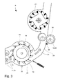
- Fig. 3 corresponds to the representation of Fig. 2 , Wherein now about the horizontal pivot axis 23 is vertically pivotable from an open to a closed position Leitblleich 24 in the closed position.
- the lower end region of the baffle 24 covers the Hußseltrommelgephaseuse 19 associated bottom plate 22, which serves as a stop 35 for the Leitblleich 24 when taking the closed position, in another embodiment, not shown here in addition to the guide plate 24 and the bottom plate 22nd designed to pivot about a pivot axis by means of a pivoting mechanism.
- the horizontal axis is located at the upper end of the floor panel 22nd In cooperation with the pivotable baffle so an enlarged outlet opening at the lowest point in Erntegut asschacht 21 can be achieved in order to eliminate the disadvantages already described can.
Landscapes
- Life Sciences & Earth Sciences (AREA)
- Environmental Sciences (AREA)
- Harvesting Machines For Specific Crops (AREA)
- Outside Dividers And Delivering Mechanisms For Harvesters (AREA)
- Harvester Elements (AREA)
- Threshing Machine Elements (AREA)
Claims (11)
- Machine de récolte agricole (2), en particulier ensileuse (1), construite sur la base d'un châssis (3), dotée d'une unité d'entraînement (19), d'un organe d'alimentation amenant le produit de récolte (10) à un tambour de hachage (14) placé en aval et d'un dispositif de broyage secondaire (16) situé en aval du tambour de hachage (14), une tôle de fond (22) partiellement enveloppante et adjacente à la tôle de guidage (24) dans le canal de transport de produit de récolte (21) étant associée au tambour de hachage (14), caractérisée en ce que la tôle de guidage (24) qui est présente du côté fond dans le canal de transport de produit de récolte (21), dans la zone comprise entre le tambour de hachage (14) et le dispositif de broyage secondaire (16) situé en aval, comprend un mécanisme de pivotement (27) conçu comme un système de transmission (26), lequel système de transmission (26) comporte un organe d'actionnement télescopique (28, 29, 31), de sorte que la tôle de guidage (24) peut pivoter verticalement autour d'un axe de pivotement horizontal (23) depuis position fermée vers une position ouverte et inversement, afin que des dépôts de produit de récolte qui se forment à cet endroit en cas d'engorgements puissent tomber vers le bas lorsque la tôle de guidage (24) se trouve dans la position ouverte, le pivotement de la tôle de guidage (24) de la position fermée vers la position ouverte se produisant lorsque le tambour de hachage (14) est découplé de l'unité d'entraînement (19) et/ou lorsque l'unité d'entraînement (19) est arrêtée.
- Machine de récolte agricole (2) selon la revendication 1, caractérisée en ce que la tôle de guidage (24) s'étend sur tout le côté fond du canal de transport de produit de récolte (21) dans la zone comprise entre le tambour de hachage (14) et le dispositif de broyage secondaire (16) situé en aval.
- Machine de récolte agricole (2) selon la revendication 1 ou 2, caractérisée en ce que l'axe de pivotement (23) se trouve à l'extrémité supérieure de la tôle de guidage (24).
- Machine de récolte agricole (2) selon l'une des revendications 1 à 3, caractérisée en ce que le système de transmission (26) est formé essentiellement par au moins un organe de transmission (26) relié par une extrémité, au moyen d'un dispositif de retenue (30), de façon rotative à la tôle de guidage (24) du canal de transport de produit de récolte (21), lequel organe de transmission est relié par l'autre extrémité, au moyen d'un autre dispositif de retenue, de façon rotative au châssis (3).
- Machine de récolte agricole (2) selon l'une des revendications 1 à 4, caractérisée en ce que ledit au moins un organe de transmission est l'organe d'actionnement télescopique (29), lequel organe d'actionnement télescopique (29) est réalisé sous la forme d'un vérin hydraulique (28) ou d'un moteur linéaire (31).
- Machine de récolte agricole (2) selon l'une des revendications 1 à 5, caractérisée en ce que le pivotement de la tôle de guidage (2) de la position fermée vers la position ouverte se produit lors de l'inversion du sens de rotation du tambour de hachage (14).
- Machine de récolte agricole (2) selon l'une des revendications 1 à 6, caractérisée en ce que le pivotement de la tôle de guidage (24) de la position fermée vers la position ouverte se produit pendant l'affûtage des couteaux hacheurs (13) disposés sur le tambour de hachage (14).
- Machine de récolte agricole (2) selon l'une des revendications 1 à 7, caractérisée en ce qu'au moins un capteur (33) est disposé en au moins un endroit à l'intérieur du carter de tambour de hachage (19) et le capteur (33) peut être utilisé comme récepteur de bruit de structure, le pivotement de la tôle de guidage (24) de la position fermée vers la position ouverte se produisant en réponse au signal de capteur X généré par le capteur (33).
- Machine de récolte agricole (2) selon l'une des revendications 1 à 8, caractérisée en ce qu'au moins un capteur (34) pour la détection du couple est disposé au moins sur le tambour de hachage (14) et/ou sur les organes de traitement (16, 17, 20) suivants, le pivotement de la tôle de guidage (24) de la position fermée vers la position ouverte se produisant en cas de dépassement d'un couple préalablement défini.
- Machine de récolte agricole (2) selon l'une des revendications 1 à 9, caractérisée en ce que le pivotement de la tôle de guidage (24) est effectué manuellement par l'opérateur (6) ou automatiquement au moyen d'un dispositif d'analyse et de commande.
- Machine de récolte agricole (2) selon l'une des revendications 1 à 10, caractérisée en ce qu'une unité de commande (7) pour la commande du mécanisme de pivotement (27) est prévue à l'intérieur de la cabine de conduite (8) associée à l'ensileuse (1).
Applications Claiming Priority (1)
| Application Number | Priority Date | Filing Date | Title |
|---|---|---|---|
| DE102007013715A DE102007013715A1 (de) | 2007-03-20 | 2007-03-20 | Landwirtschaftliche Erntemaschine |
Publications (3)
| Publication Number | Publication Date |
|---|---|
| EP1972191A1 EP1972191A1 (fr) | 2008-09-24 |
| EP1972191B1 EP1972191B1 (fr) | 2010-09-08 |
| EP1972191B2 true EP1972191B2 (fr) | 2014-12-03 |
Family
ID=39523802
Family Applications (1)
| Application Number | Title | Priority Date | Filing Date |
|---|---|---|---|
| EP07123612.9A Active EP1972191B2 (fr) | 2007-03-20 | 2007-12-19 | Moissonneuse agricole |
Country Status (5)
| Country | Link |
|---|---|
| US (1) | US20080234020A1 (fr) |
| EP (1) | EP1972191B2 (fr) |
| AT (1) | ATE480138T1 (fr) |
| DE (2) | DE102007013715A1 (fr) |
| RU (1) | RU2457662C2 (fr) |
Cited By (1)
| Publication number | Priority date | Publication date | Assignee | Title |
|---|---|---|---|---|
| CN108633499A (zh) * | 2018-05-18 | 2018-10-12 | 孙琳琳 | 一种医疗中药玉米秆芯回收装置 |
Families Citing this family (24)
| Publication number | Priority date | Publication date | Assignee | Title |
|---|---|---|---|---|
| DE602007003260D1 (de) * | 2006-06-22 | 2009-12-31 | Maasland Nv | Vorrichtung zur Saatgutverarbeitung mit Aufnahme-/Schneidegerät |
| BE1018656A3 (nl) * | 2009-02-13 | 2011-06-07 | Cnh Belgium Nv | Een hakselaar met een blazer. |
| DE102011082727A1 (de) * | 2011-09-15 | 2013-03-21 | Deere & Company | Feldhäcksler mit einer Anordnung zur Messung des Erntegutdurchsatzes |
| DE102012017149A1 (de) * | 2012-08-30 | 2014-03-06 | Class Selbstfahrende Erntemaschinen Gmbh | Erntemaschine mit Gutzufuhrregelung |
| DE102012108542A1 (de) * | 2012-09-13 | 2014-06-12 | Claas Selbstfahrende Erntemaschinen Gmbh | Landwirtschaftliche Erntemaschine |
| DE102012112265A1 (de) * | 2012-12-14 | 2014-06-18 | Claas Selbstfahrende Erntemaschinen Gmbh | Nachzerkleinerungsvorrichtung |
| BE1021144B1 (nl) * | 2013-05-06 | 2016-01-08 | Cnh Industrial Belgium Nv | Veldhakselaar met verbeterde gewasstroming |
| DE102013106296A1 (de) * | 2013-06-18 | 2014-12-18 | Claas Selbstfahrende Erntemaschinen Gmbh | Nachzerkleinerungsvorrichtung |
| EP2944182B2 (fr) * | 2014-05-12 | 2023-02-22 | CNH Industrial Belgium nv | Ramasseuse-hacheuse comportant un flux de récolte amélioré |
| DE102014106696A1 (de) | 2014-05-13 | 2015-11-19 | Claas Selbstfahrende Erntemaschinen Gmbh | Feldhäcksler |
| DE102014219049B4 (de) | 2014-09-22 | 2024-07-11 | Deere & Company | Feldhäcksler mit reversierbarer Konditioniereinrichtung |
| US10306834B2 (en) * | 2014-11-17 | 2019-06-04 | Cnh Industrial America Llc | Chopper and spreader for an agricultural harvester |
| BE1024803B1 (nl) * | 2017-05-12 | 2018-07-03 | Cnh Industrial Belgium Nv | Werkwijze voor het slijpen van messen van een landbouwvoertuig |
| DE102017215891B4 (de) | 2017-09-08 | 2026-03-12 | Deere & Company | Steueranordnung zur Kontrolle einer an der Unterseite eines stromab einer Häckseltrommel angeordneten Kanals eines Feldhäckslers angeordneten Verschlusseinrichtung |
| DE102019110768A1 (de) * | 2018-05-04 | 2019-11-07 | Claas Saulgau Gmbh | Grasschacht eines landwirtschaftlichen Erntefahrzeugs und landwirtschaftliches Erntefahrzeug |
| CN109287298A (zh) * | 2018-09-29 | 2019-02-01 | 李丽芬 | 一种农业机械秸秆粉碎处理装置 |
| EP3695705B1 (fr) | 2019-02-14 | 2022-11-16 | Deere & Company | Machine de récolte avec système de détection de débit de récolte |
| RU192092U1 (ru) * | 2019-03-26 | 2019-09-03 | Общество с ограниченной ответственностью "Комбайновый завод "Ростсельмаш" | Доизмельчитель кормоуборочного комбайна |
| EP3756441B1 (fr) * | 2019-06-25 | 2023-02-01 | CNH Industrial Belgium N.V. | Plaque d'usure de tête de coupe réglable pour une récolteuse-hacheuse |
| US11570951B2 (en) | 2019-12-19 | 2023-02-07 | Deere & Company | Forage harvester with processing component protection |
| CN111357503A (zh) * | 2020-05-04 | 2020-07-03 | 刘林 | 玉米秸秆切割设备 |
| CN112703899B (zh) * | 2020-12-09 | 2022-08-23 | 北京农业智能装备技术研究中心 | 打捆机作业速度自适应系统 |
| GB202407605D0 (en) * | 2024-05-29 | 2024-07-10 | Agco Int Gmbh | A forage harvester |
| DE102024118901A1 (de) * | 2024-07-03 | 2026-01-08 | Claas Selbstfahrende Erntemaschinen Gmbh | Selbstfahrender Feldhäcksler |
Citations (1)
| Publication number | Priority date | Publication date | Assignee | Title |
|---|---|---|---|---|
| DE3023688A1 (de) † | 1980-06-25 | 1982-01-14 | Claas Ohg, 4834 Harsewinkel | Erntemaschine |
Family Cites Families (16)
| Publication number | Priority date | Publication date | Assignee | Title |
|---|---|---|---|---|
| US1038926A (en) * | 1908-08-05 | 1912-09-17 | David A Mcconnell | Closure for threshing-machines. |
| US2959175A (en) * | 1958-03-26 | 1960-11-08 | Allis Chalmers Mfg Co | Mounting for a threshing cylinder concave |
| FR2053287B1 (fr) * | 1969-07-30 | 1973-03-16 | Clayson Nv | |
| FR2663499B1 (fr) * | 1990-06-25 | 1992-10-16 | Hesston Braud | Procede pour l'affutage des couteaux d'un tambour rotatif et le reglage du contre-couteau fixe cooperant avec ceux-ci et dispositif mettant en óoeuvre ce procede. |
| DE4040888A1 (de) * | 1990-12-20 | 1992-06-25 | Claas Ohg | Haecksler zum zerkleinern von halmfoermigem erntegut |
| US5186683A (en) * | 1991-09-23 | 1993-02-16 | Case Corporation | Stone trap assembly for a combine |
| DE4215696A1 (de) * | 1992-05-13 | 1993-11-18 | Claas Ohg | Selbstfahrender Feldhäcksler |
| DE19532290C2 (de) * | 1995-09-01 | 2001-11-29 | Claas Kgaa Mbh | Feldhäcksler |
| DE19532669C2 (de) * | 1995-09-05 | 2003-10-09 | Case Harvesting Sys Gmbh | Häckselaggregat und Auswurfschacht für einen Feldhäcksler |
| US5882257A (en) * | 1997-09-23 | 1999-03-16 | Case Corporation | Rock trap sump door latch |
| DE19742846B4 (de) * | 1997-09-29 | 2006-01-05 | Claas Selbstfahrende Erntemaschinen Gmbh | Selbstfahrender Feldhäcksler |
| DE59807182D1 (de) * | 1998-01-16 | 2003-03-20 | Claas Selbstfahr Erntemasch | Messvorrichtung an einer fahrbaren Erntemaschine |
| EP1044597B1 (fr) * | 1999-04-12 | 2003-07-02 | CNH Belgium N.V. | Détection et éjection de pierres pour convoyeur d'une moissonneuse-batteuse |
| DE10021657C2 (de) * | 2000-05-04 | 2002-08-01 | Krone Bernhard Gmbh Maschf | Erntemaschine, insbesondere selbstfahrender Feldhäcksler |
| DE10241216A1 (de) * | 2002-09-06 | 2004-03-18 | Deere & Company, Moline | Nachweiseinrichtung zum Nachweis eines Gutstaus in einer Erntemaschine |
| DE10346116A1 (de) * | 2003-10-04 | 2005-04-21 | Deere & Co | Häckseleinrichtung für einen Feldhäcksler |
-
2007
- 2007-03-20 DE DE102007013715A patent/DE102007013715A1/de not_active Withdrawn
- 2007-12-19 EP EP07123612.9A patent/EP1972191B2/fr active Active
- 2007-12-19 DE DE502007004992T patent/DE502007004992D1/de active Active
- 2007-12-19 AT AT07123612T patent/ATE480138T1/de active
-
2008
- 2008-02-26 RU RU2008106840/13A patent/RU2457662C2/ru active
- 2008-02-28 US US12/039,155 patent/US20080234020A1/en not_active Abandoned
Patent Citations (1)
| Publication number | Priority date | Publication date | Assignee | Title |
|---|---|---|---|---|
| DE3023688A1 (de) † | 1980-06-25 | 1982-01-14 | Claas Ohg, 4834 Harsewinkel | Erntemaschine |
Non-Patent Citations (1)
| Title |
|---|
| J. DEERE: "Selbstfahrende Feldhäcksler 6650, 6750, 6850 und 6950 (Seriennr. 504992-)", BETRIEBSANLEITUNG, 2000 † |
Cited By (1)
| Publication number | Priority date | Publication date | Assignee | Title |
|---|---|---|---|---|
| CN108633499A (zh) * | 2018-05-18 | 2018-10-12 | 孙琳琳 | 一种医疗中药玉米秆芯回收装置 |
Also Published As
| Publication number | Publication date |
|---|---|
| DE102007013715A1 (de) | 2008-09-25 |
| DE502007004992D1 (de) | 2010-10-21 |
| EP1972191B1 (fr) | 2010-09-08 |
| RU2008106840A (ru) | 2009-09-10 |
| RU2457662C2 (ru) | 2012-08-10 |
| ATE480138T1 (de) | 2010-09-15 |
| EP1972191A1 (fr) | 2008-09-24 |
| US20080234020A1 (en) | 2008-09-25 |
Similar Documents
| Publication | Publication Date | Title |
|---|---|---|
| EP1972191B2 (fr) | Moissonneuse agricole | |
| DE102017204511B4 (de) | Landwirtschaftliche Erntemaschine zur Bearbeitung und Förderung von Erntegut mit einer Sensoranordnung zur Erkennung von unerwünschten Gefahr- und Inhaltsstoffen im Erntegut | |
| EP1997366B1 (fr) | Moissonneuse agricole dotée d'un dispositif de détection des corps étrangers | |
| DE102008006882B4 (de) | Erntemaschinenkombination zur Pflanzenresteverwertung | |
| EP1961288B1 (fr) | Dispositif destiné au réglage de la position de l'organe d'accélération ultérieure dans une moissonneuse agricole | |
| EP3662741A1 (fr) | Machine de travail agricole ainsi que procédé de fonctionnement d'une machine de travail agricole | |
| EP2250870B1 (fr) | Agencement de hachage et de répartition de résidus de produits de récolte pour une moissonneuse-batteuse | |
| EP2175710B1 (fr) | Moissonneuse-batteuse avec un transporteur à tambour supplémentaire pour l'évacuation de la paille et un seul clapet pour l'alternance entre le déversement des andains et le hachage de la paille | |
| EP2022310B1 (fr) | Dispositif de dépôt de résidus de moissons commutable entre fonctionnement de distribution large et collecteur éjecteur pour une moissonneuse-batteuse | |
| DE102010002343A1 (de) | Feldhäcksler mit einer Häckseleinrichtung und einer stromab der Häckseleinrichtung angeordneten Nachbearbeitungseinrichtung | |
| DE10063550B4 (de) | Mähdrescher mit Häckseleinrichtung | |
| EP3909416B1 (fr) | Ramasseuse-hacheuse dotée d'un canal de transport permettant de transporter le produit de la récolte et procédé de transport du produit de la récolte | |
| EP2250869B1 (fr) | Agencement de hachage et de répartition de résidus de produits de récolte pour une moissonneuse-batteuse | |
| EP3150060B1 (fr) | Broyeur de paille de moissonneuse-batteuse comprenant des couteaux fixes et barre de friction | |
| EP0727135B1 (fr) | Moissonneuse-batteuse | |
| EP2708107B1 (fr) | Moissonneuse-batteuse automotrice | |
| EP2796031B2 (fr) | Moissonneuse | |
| EP2368417A1 (fr) | Moissonneuse dotée d'un dispositif de criblage pour l'air de refroidissement | |
| EP2179642B2 (fr) | Moissonneuse agricole | |
| DE102016118353A1 (de) | Feldhäcksler mit einem Erntegutbearbeitungskanal und einer Messleiste zur Erfassung einer Querverteilung des Erntegutes in dem Erntegutbearbeitungskanal | |
| BE1023629B1 (de) | Erntegutresteverteileinrichtung für einen Mähdrescher | |
| EP2853147A1 (fr) | Ramasseuse-hacheuse dotée d'un dispositif de post-accélération | |
| DE102024114424A1 (de) | Selbstfahrender Feldhäcksler | |
| DE102019008801B4 (de) | Einzugsanordnung mit Fangblech und Feldhäcksler mit Einzugsanordnung | |
| EP2656723B1 (fr) | Agencement de hachage et de répartition de résidus de produits de récolte pour une moissonneuse-batteuse doté d'éléments de guidage pouvant être amenés dans une position d'andainage |
Legal Events
| Date | Code | Title | Description |
|---|---|---|---|
| PUAI | Public reference made under article 153(3) epc to a published international application that has entered the european phase |
Free format text: ORIGINAL CODE: 0009012 |
|
| AK | Designated contracting states |
Kind code of ref document: A1 Designated state(s): AT BE BG CH CY CZ DE DK EE ES FI FR GB GR HU IE IS IT LI LT LU LV MC MT NL PL PT RO SE SI SK TR |
|
| AX | Request for extension of the european patent |
Extension state: AL BA HR MK RS |
|
| 17P | Request for examination filed |
Effective date: 20090324 |
|
| 17Q | First examination report despatched |
Effective date: 20090427 |
|
| AKX | Designation fees paid |
Designated state(s): AT BE BG CH CY CZ DE DK EE ES FI FR GB GR HU IE IS IT LI LT LU LV MC MT NL PL PT RO SE SI SK TR |
|
| GRAP | Despatch of communication of intention to grant a patent |
Free format text: ORIGINAL CODE: EPIDOSNIGR1 |
|
| GRAS | Grant fee paid |
Free format text: ORIGINAL CODE: EPIDOSNIGR3 |
|
| GRAA | (expected) grant |
Free format text: ORIGINAL CODE: 0009210 |
|
| AK | Designated contracting states |
Kind code of ref document: B1 Designated state(s): AT BE BG CH CY CZ DE DK EE ES FI FR GB GR HU IE IS IT LI LT LU LV MC MT NL PL PT RO SE SI SK TR |
|
| REG | Reference to a national code |
Ref country code: GB Ref legal event code: FG4D Free format text: NOT ENGLISH |
|
| REG | Reference to a national code |
Ref country code: CH Ref legal event code: EP |
|
| REG | Reference to a national code |
Ref country code: IE Ref legal event code: FG4D Free format text: LANGUAGE OF EP DOCUMENT: GERMAN |
|
| REF | Corresponds to: |
Ref document number: 502007004992 Country of ref document: DE Date of ref document: 20101021 Kind code of ref document: P |
|
| REG | Reference to a national code |
Ref country code: NL Ref legal event code: VDEP Effective date: 20100908 |
|
| PG25 | Lapsed in a contracting state [announced via postgrant information from national office to epo] |
Ref country code: FI Free format text: LAPSE BECAUSE OF FAILURE TO SUBMIT A TRANSLATION OF THE DESCRIPTION OR TO PAY THE FEE WITHIN THE PRESCRIBED TIME-LIMIT Effective date: 20100908 Ref country code: LT Free format text: LAPSE BECAUSE OF FAILURE TO SUBMIT A TRANSLATION OF THE DESCRIPTION OR TO PAY THE FEE WITHIN THE PRESCRIBED TIME-LIMIT Effective date: 20100908 |
|
| LTIE | Lt: invalidation of european patent or patent extension |
Effective date: 20100908 |
|
| PG25 | Lapsed in a contracting state [announced via postgrant information from national office to epo] |
Ref country code: PL Free format text: LAPSE BECAUSE OF FAILURE TO SUBMIT A TRANSLATION OF THE DESCRIPTION OR TO PAY THE FEE WITHIN THE PRESCRIBED TIME-LIMIT Effective date: 20100908 Ref country code: SI Free format text: LAPSE BECAUSE OF FAILURE TO SUBMIT A TRANSLATION OF THE DESCRIPTION OR TO PAY THE FEE WITHIN THE PRESCRIBED TIME-LIMIT Effective date: 20100908 Ref country code: CY Free format text: LAPSE BECAUSE OF FAILURE TO SUBMIT A TRANSLATION OF THE DESCRIPTION OR TO PAY THE FEE WITHIN THE PRESCRIBED TIME-LIMIT Effective date: 20100908 |
|
| REG | Reference to a national code |
Ref country code: IE Ref legal event code: FD4D |
|
| PG25 | Lapsed in a contracting state [announced via postgrant information from national office to epo] |
Ref country code: LV Free format text: LAPSE BECAUSE OF FAILURE TO SUBMIT A TRANSLATION OF THE DESCRIPTION OR TO PAY THE FEE WITHIN THE PRESCRIBED TIME-LIMIT Effective date: 20100908 Ref country code: NL Free format text: LAPSE BECAUSE OF FAILURE TO SUBMIT A TRANSLATION OF THE DESCRIPTION OR TO PAY THE FEE WITHIN THE PRESCRIBED TIME-LIMIT Effective date: 20100908 Ref country code: SE Free format text: LAPSE BECAUSE OF FAILURE TO SUBMIT A TRANSLATION OF THE DESCRIPTION OR TO PAY THE FEE WITHIN THE PRESCRIBED TIME-LIMIT Effective date: 20100908 Ref country code: GR Free format text: LAPSE BECAUSE OF FAILURE TO SUBMIT A TRANSLATION OF THE DESCRIPTION OR TO PAY THE FEE WITHIN THE PRESCRIBED TIME-LIMIT Effective date: 20101209 |
|
| PG25 | Lapsed in a contracting state [announced via postgrant information from national office to epo] |
Ref country code: IE Free format text: LAPSE BECAUSE OF FAILURE TO SUBMIT A TRANSLATION OF THE DESCRIPTION OR TO PAY THE FEE WITHIN THE PRESCRIBED TIME-LIMIT Effective date: 20100908 |
|
| PLBI | Opposition filed |
Free format text: ORIGINAL CODE: 0009260 |
|
| PG25 | Lapsed in a contracting state [announced via postgrant information from national office to epo] |
Ref country code: CZ Free format text: LAPSE BECAUSE OF FAILURE TO SUBMIT A TRANSLATION OF THE DESCRIPTION OR TO PAY THE FEE WITHIN THE PRESCRIBED TIME-LIMIT Effective date: 20100908 Ref country code: EE Free format text: LAPSE BECAUSE OF FAILURE TO SUBMIT A TRANSLATION OF THE DESCRIPTION OR TO PAY THE FEE WITHIN THE PRESCRIBED TIME-LIMIT Effective date: 20100908 Ref country code: RO Free format text: LAPSE BECAUSE OF FAILURE TO SUBMIT A TRANSLATION OF THE DESCRIPTION OR TO PAY THE FEE WITHIN THE PRESCRIBED TIME-LIMIT Effective date: 20100908 Ref country code: IT Free format text: LAPSE BECAUSE OF FAILURE TO SUBMIT A TRANSLATION OF THE DESCRIPTION OR TO PAY THE FEE WITHIN THE PRESCRIBED TIME-LIMIT Effective date: 20100908 Ref country code: SK Free format text: LAPSE BECAUSE OF FAILURE TO SUBMIT A TRANSLATION OF THE DESCRIPTION OR TO PAY THE FEE WITHIN THE PRESCRIBED TIME-LIMIT Effective date: 20100908 Ref country code: IS Free format text: LAPSE BECAUSE OF FAILURE TO SUBMIT A TRANSLATION OF THE DESCRIPTION OR TO PAY THE FEE WITHIN THE PRESCRIBED TIME-LIMIT Effective date: 20110108 Ref country code: PT Free format text: LAPSE BECAUSE OF FAILURE TO SUBMIT A TRANSLATION OF THE DESCRIPTION OR TO PAY THE FEE WITHIN THE PRESCRIBED TIME-LIMIT Effective date: 20110110 |
|
| 26 | Opposition filed |
Opponent name: DEERE & COMPANY Effective date: 20110524 |
|
| PG25 | Lapsed in a contracting state [announced via postgrant information from national office to epo] |
Ref country code: ES Free format text: LAPSE BECAUSE OF FAILURE TO SUBMIT A TRANSLATION OF THE DESCRIPTION OR TO PAY THE FEE WITHIN THE PRESCRIBED TIME-LIMIT Effective date: 20101219 |
|
| PLAX | Notice of opposition and request to file observation + time limit sent |
Free format text: ORIGINAL CODE: EPIDOSNOBS2 |
|
| PG25 | Lapsed in a contracting state [announced via postgrant information from national office to epo] |
Ref country code: MC Free format text: LAPSE BECAUSE OF NON-PAYMENT OF DUE FEES Effective date: 20101231 |
|
| REG | Reference to a national code |
Ref country code: DE Ref legal event code: R026 Ref document number: 502007004992 Country of ref document: DE Effective date: 20110524 |
|
| PG25 | Lapsed in a contracting state [announced via postgrant information from national office to epo] |
Ref country code: DK Free format text: LAPSE BECAUSE OF FAILURE TO SUBMIT A TRANSLATION OF THE DESCRIPTION OR TO PAY THE FEE WITHIN THE PRESCRIBED TIME-LIMIT Effective date: 20100908 |
|
| REG | Reference to a national code |
Ref country code: FR Ref legal event code: ST Effective date: 20110831 |
|
| PG25 | Lapsed in a contracting state [announced via postgrant information from national office to epo] |
Ref country code: FR Free format text: LAPSE BECAUSE OF NON-PAYMENT OF DUE FEES Effective date: 20110103 |
|
| PLBB | Reply of patent proprietor to notice(s) of opposition received |
Free format text: ORIGINAL CODE: EPIDOSNOBS3 |
|
| PG25 | Lapsed in a contracting state [announced via postgrant information from national office to epo] |
Ref country code: MT Free format text: LAPSE BECAUSE OF FAILURE TO SUBMIT A TRANSLATION OF THE DESCRIPTION OR TO PAY THE FEE WITHIN THE PRESCRIBED TIME-LIMIT Effective date: 20100908 |
|
| REG | Reference to a national code |
Ref country code: CH Ref legal event code: PL |
|
| GBPC | Gb: european patent ceased through non-payment of renewal fee |
Effective date: 20111219 |
|
| PG25 | Lapsed in a contracting state [announced via postgrant information from national office to epo] |
Ref country code: HU Free format text: LAPSE BECAUSE OF FAILURE TO SUBMIT A TRANSLATION OF THE DESCRIPTION OR TO PAY THE FEE WITHIN THE PRESCRIBED TIME-LIMIT Effective date: 20110309 Ref country code: BG Free format text: LAPSE BECAUSE OF FAILURE TO SUBMIT A TRANSLATION OF THE DESCRIPTION OR TO PAY THE FEE WITHIN THE PRESCRIBED TIME-LIMIT Effective date: 20100908 Ref country code: LU Free format text: LAPSE BECAUSE OF NON-PAYMENT OF DUE FEES Effective date: 20101219 |
|
| PG25 | Lapsed in a contracting state [announced via postgrant information from national office to epo] |
Ref country code: TR Free format text: LAPSE BECAUSE OF FAILURE TO SUBMIT A TRANSLATION OF THE DESCRIPTION OR TO PAY THE FEE WITHIN THE PRESCRIBED TIME-LIMIT Effective date: 20100908 Ref country code: GB Free format text: LAPSE BECAUSE OF NON-PAYMENT OF DUE FEES Effective date: 20111219 Ref country code: CH Free format text: LAPSE BECAUSE OF NON-PAYMENT OF DUE FEES Effective date: 20111231 Ref country code: LI Free format text: LAPSE BECAUSE OF NON-PAYMENT OF DUE FEES Effective date: 20111231 |
|
| PG25 | Lapsed in a contracting state [announced via postgrant information from national office to epo] |
Ref country code: BG Free format text: LAPSE BECAUSE OF FAILURE TO SUBMIT A TRANSLATION OF THE DESCRIPTION OR TO PAY THE FEE WITHIN THE PRESCRIBED TIME-LIMIT Effective date: 20101208 |
|
| REG | Reference to a national code |
Ref country code: AT Ref legal event code: MM01 Ref document number: 480138 Country of ref document: AT Kind code of ref document: T Effective date: 20121219 |
|
| PG25 | Lapsed in a contracting state [announced via postgrant information from national office to epo] |
Ref country code: AT Free format text: LAPSE BECAUSE OF NON-PAYMENT OF DUE FEES Effective date: 20121219 |
|
| PUAH | Patent maintained in amended form |
Free format text: ORIGINAL CODE: 0009272 |
|
| STAA | Information on the status of an ep patent application or granted ep patent |
Free format text: STATUS: PATENT MAINTAINED AS AMENDED |
|
| 27A | Patent maintained in amended form |
Effective date: 20141203 |
|
| AK | Designated contracting states |
Kind code of ref document: B2 Designated state(s): AT BE BG CH CY CZ DE DK EE ES FI FR GB GR HU IE IS IT LI LT LU LV MC MT NL PL PT RO SE SI SK TR |
|
| REG | Reference to a national code |
Ref country code: DE Ref legal event code: R102 Ref document number: 502007004992 Country of ref document: DE |
|
| REG | Reference to a national code |
Ref country code: DE Ref legal event code: R102 Ref document number: 502007004992 Country of ref document: DE Effective date: 20141203 |
|
| PG25 | Lapsed in a contracting state [announced via postgrant information from national office to epo] |
Ref country code: LV Free format text: LAPSE BECAUSE OF FAILURE TO SUBMIT A TRANSLATION OF THE DESCRIPTION OR TO PAY THE FEE WITHIN THE PRESCRIBED TIME-LIMIT Effective date: 20141203 |
|
| REG | Reference to a national code |
Ref country code: DE Ref legal event code: R081 Ref document number: 502007004992 Country of ref document: DE Owner name: CLAAS SAULGAU GMBH, DE Free format text: FORMER OWNER: CLAAS SELBSTFAHRENDE ERNTEMASCHINEN GMBH, 33428 HARSEWINKEL, DE |
|
| P01 | Opt-out of the competence of the unified patent court (upc) registered |
Effective date: 20230602 |
|
| PGFP | Annual fee paid to national office [announced via postgrant information from national office to epo] |
Ref country code: DE Payment date: 20251211 Year of fee payment: 19 |
|
| PGFP | Annual fee paid to national office [announced via postgrant information from national office to epo] |
Ref country code: BE Payment date: 20251219 Year of fee payment: 19 |