EP3909416B1 - Ramasseuse-hacheuse dotée d'un canal de transport permettant de transporter le produit de la récolte et procédé de transport du produit de la récolte - Google Patents
Ramasseuse-hacheuse dotée d'un canal de transport permettant de transporter le produit de la récolte et procédé de transport du produit de la récolte Download PDFInfo
- Publication number
- EP3909416B1 EP3909416B1 EP21173298.7A EP21173298A EP3909416B1 EP 3909416 B1 EP3909416 B1 EP 3909416B1 EP 21173298 A EP21173298 A EP 21173298A EP 3909416 B1 EP3909416 B1 EP 3909416B1
- Authority
- EP
- European Patent Office
- Prior art keywords
- crop
- forage harvester
- accelerator
- air flow
- post
- Prior art date
- Legal status (The legal status is an assumption and is not a legal conclusion. Google has not performed a legal analysis and makes no representation as to the accuracy of the status listed.)
- Active
Links
- 239000004459 forage Substances 0.000 title claims description 61
- 238000000034 method Methods 0.000 title claims description 8
- 239000000463 material Substances 0.000 title description 3
- 230000001133 acceleration Effects 0.000 claims description 54
- 238000003306 harvesting Methods 0.000 claims description 51
- 240000008042 Zea mays Species 0.000 claims description 41
- 235000005824 Zea mays ssp. parviglumis Nutrition 0.000 claims description 41
- 235000002017 Zea mays subsp mays Nutrition 0.000 claims description 41
- 235000005822 corn Nutrition 0.000 claims description 41
- 244000025254 Cannabis sativa Species 0.000 claims description 22
- 239000000446 fuel Substances 0.000 description 5
- 229920002472 Starch Polymers 0.000 description 3
- 230000000694 effects Effects 0.000 description 3
- 235000019698 starch Nutrition 0.000 description 3
- 239000008107 starch Substances 0.000 description 3
- 241001124569 Lycaenidae Species 0.000 description 1
- 230000001419 dependent effect Effects 0.000 description 1
- 230000001960 triggered effect Effects 0.000 description 1
Images

Classifications
-
- A—HUMAN NECESSITIES
- A01—AGRICULTURE; FORESTRY; ANIMAL HUSBANDRY; HUNTING; TRAPPING; FISHING
- A01D—HARVESTING; MOWING
- A01D43/00—Mowers combined with apparatus performing additional operations while mowing
- A01D43/08—Mowers combined with apparatus performing additional operations while mowing with means for cutting up the mown crop, e.g. forage harvesters
- A01D43/081—Mowers combined with apparatus performing additional operations while mowing with means for cutting up the mown crop, e.g. forage harvesters specially adapted for ensilage of maize
-
- A—HUMAN NECESSITIES
- A01—AGRICULTURE; FORESTRY; ANIMAL HUSBANDRY; HUNTING; TRAPPING; FISHING
- A01D—HARVESTING; MOWING
- A01D43/00—Mowers combined with apparatus performing additional operations while mowing
- A01D43/08—Mowers combined with apparatus performing additional operations while mowing with means for cutting up the mown crop, e.g. forage harvesters
- A01D43/085—Control or measuring arrangements specially adapted therefor
-
- A—HUMAN NECESSITIES
- A01—AGRICULTURE; FORESTRY; ANIMAL HUSBANDRY; HUNTING; TRAPPING; FISHING
- A01D—HARVESTING; MOWING
- A01D43/00—Mowers combined with apparatus performing additional operations while mowing
- A01D43/08—Mowers combined with apparatus performing additional operations while mowing with means for cutting up the mown crop, e.g. forage harvesters
- A01D43/086—Mowers combined with apparatus performing additional operations while mowing with means for cutting up the mown crop, e.g. forage harvesters and means for collecting, gathering or loading mown material
Definitions
- the present invention relates to a forage harvester with a conveying channel for conveying crops, which is arranged downstream of a shredding device for the crops in a conveying direction of the crops, the conveying channel comprising a post-accelerator which is arranged in a grass harvesting arrangement in an acceleration position in which it is in the Conveyor channel is set and provided for accelerating the crop, and wherein in a corn harvesting arrangement a conditioner is accommodated in the conveying channel, which is not arranged in the conveying channel in the grass harvesting arrangement.
- the present invention further relates to a method for conveying crops, in particular corn, in a conveying channel of such a forage harvester.
- Forage harvesters have a conveying channel which is arranged downstream of a shredding device, which is intended for shredding crops, in a conveying direction of the crops.
- a post-accelerator is regularly arranged in the conveyor channel, which increases the speed of the grass so that it can be loaded onto a transport trolley through an ejection pipe arranged downstream of the conveyor channel.
- the post-accelerator is conventionally preceded by a processor with which the corn kernels are broken up in a corn operation in which corn is harvested with the forage harvester, so that the starch inside the corn kernels is accessible from the outside.
- the corn kernels are also accelerated by the processor.
- the publication EP 1 145 616 A1 discloses a forage harvester in which the ejection accelerator can only be pivoted into the ejection channel when necessary can. In particular, it discloses incorporating either the ejection accelerator or a squeezing device into the conveying channel. This can reduce the fuel consumption of the forage harvester and wear on the ejection accelerator.
- the document US 2015/327439 A1 discloses a forage harvester according to the preamble of claim 1.
- the object of the present invention is to create a forage harvester in which uniform overloading of the crop is ensured both in a grass harvesting arrangement and in a corn harvesting arrangement, with fuel consumption and/or wear being further reduced.
- a forage harvester For this, a forage harvester is created.
- the forage harvester has a conveyor channel for conveying crops.
- the conveying channel is arranged downstream of a shredding device for the crop in a conveying direction of the crop.
- the crop is shredded using the shredding device.
- An ejection pipe is also arranged downstream of the conveying channel, preferably viewed in the conveying direction.
- the ejection tube is intended for ejecting the crop onto a transport trolley.
- the delivery channel includes a post-accelerator which is arranged in a grass harvesting arrangement in an acceleration position in which it is set in the delivery channel.
- the post-accelerator is intended to accelerate the crop.
- a conditioner is accommodated in the conveying channel, which is not arranged in the conveying channel in the grass harvesting arrangement.
- the conditioner is intended for processing corn.
- the processor breaks the corn kernels open so that the starch inside the corn kernels is accessible from the outside.
- the forage harvester is characterized by the fact that it includes a fan in the corn harvesting arrangement that is used to accelerate the crop.
- a blower in the sense of the invention is provided for accelerating the crop without having a mechanical effect on the crop. Instead, an air stream is used to accelerate.
- the post-accelerator in the corn harvesting arrangement can be adjusted from the acceleration position to a blower position, in which it is at least partially exposed from the conveying channel and acts as a blower.
- a blower position in which it is at least partially exposed from the conveying channel and acts as a blower.
- the after-accelerator is used as a fan.
- the post-accelerator preferably has an acceleration rotor with acceleration blades, which interact mechanically with the crop in the acceleration position.
- the acceleration blades are preferably provided for generating the air flow.
- the secondary accelerator is driven not only in the acceleration position, but also in the fan position.
- the acceleration blades in the fan position do not have a mechanical effect on the crop. Instead, they create the airflow that affects the crop.
- the forage harvester therefore consumes less fuel when the after-accelerator is operated in the blower position. Since the crop does not have a mechanical effect on the acceleration blades in the blower position, the wear caused on the acceleration blades is lower. This also allows the forage harvester to operate more quietly.
- the conditioner is sufficient to accelerate the harvest, especially with large quantities of crop.
- the post-accelerator can also be operated in the acceleration position in the corn harvesting arrangement as is conventional.
- the forage harvester preferably includes a control unit which is set up to adjust the post-accelerator from the acceleration position to the blower position. This can preferably be done automatically, especially if the presence of a conditioner in the corn harvest configuration is detected by sensors or displayed manually. However, the adjustment of the after-accelerator from the acceleration position to the fan position and/or back can also be triggered manually.
- the control unit is further preferably set up to adjust the air flow generated by the after-accelerator in the blower position. At least the strength of the air flow is preferably adjusted. Additionally or alternatively, the direction of the air flow can also be adjustable.
- the control unit is preferably set up to continuously or gradually adjust the air flow generated by the after-accelerator in the blower position.
- a strength of the air flow can be changed by increasing a speed of the acceleration rotor and/or changing a distance of the acceleration rotor from a rear wall of the post-accelerator.
- a fan output of the secondary accelerator can be adjusted, for example, depending on the crop and/or depending on the operating values of the forage harvester and/or depending on current harvest conditions.
- the direction of the air flow can be adjustable.
- adjustable current guide elements are provided in the delivery channel and/or on the post-accelerator.
- the flow guide elements can be adjustable in an analogous manner to adjusting the strength of the air flow depending on the crop and/or depending on the operating values of the forage harvester and/or depending on current harvest conditions, in particular a current crop quantity and/or current crop distribution.
- the conveying channel has a sensor for detecting the quantity of crop and/or distribution of crop.
- the control unit is set up to adjust the strength and/or direction of the air flow depending on the amount of crop and/or the distribution of crop.
- control unit is set up to automatically adjust the air flow.
- air flow can also be provided in an adaptable manner depending on current settings, in particular those made by an operator.
- forage harvester has an operating unit for an operator, which is set up to manually adjust the air flow.
- the crop flow is evened out when entering and/or leaving the crop, where the amount of crop processed is reduced, so that the crop can be evenly overloaded into the transport vehicle.
- the post-accelerator can be moved and/or pivoted from the acceleration position into the blower position. It is particularly preferably provided such that it can be pivoted.
- the secondary accelerator has at least one outlet in the fan position, which is arranged on a side facing the delivery channel and serves as a passage for the air flow.
- the outlet in particular its size and shape, can be adjusted by the current-conducting elements. This can influence the strength and direction of the airflow.
- the after-accelerator preferably has one or more inlets in the blower position, through which the air flow can penetrate into an interior of the after-accelerator. The inlets are preferably not arranged facing the delivery channel.
- the object is further achieved with a method for conveying crops, in particular for conveying corn, in a conveying channel of a forage harvester according to the invention.
- the method provides that the crop is accelerated, at least in a corn harvesting arrangement in which a conditioner is accommodated in the conveying channel, by applying an air flow from a fan. This means that not only large quantities of crop, but also small amounts of crop, for example when entering or leaving the crop, with reduced fuel consumption and reduced wear, can be loaded into the transport vehicle in a uniform flow of crop.
- the after-accelerator is used as a fan to generate the air flow.
- the post-accelerator can also be operated in an acceleration position both in the corn harvesting arrangement and in a grass harvesting arrangement, in which it acts mechanically on the crop.
- the post-accelerator can therefore also be operated in a conventional manner.
- the air flow is adjusted manually or automatically depending on the crop and/or depending on the operating values of the forage harvester and/or depending on the current harvest conditions.
- a strength and/or direction of the air flow (S) is preferably adjusted continuously or gradually.
- the air flow generated is changed continuously or gradually.
- the object is further achieved with the use of a fan to generate an air flow to accelerate crops in a corn harvesting arrangement of a forage harvester.
- the air flow from the fan is preferably used for small quantities of crop in order to equalize the flow of crop so that it can be evenly loaded onto a transport trolley.
- Fig. 1 shows a forage harvester 10 according to the prior art.
- the forage harvester 10 has a collection unit 5, which is intended for drawing in crops (not shown) into the forage harvester 10 in a harvesting operation (not designated), in which the forage harvester 10 is driven in a direction of travel F over a field (not shown). is.
- the collection unit 5 is arranged between front wheels 4 of the forage harvester in the direction of travel F at the front.
- An attachment 3, for example a corn header for harvesting corn, a mower for harvesting grass or a pick-up for picking up grass, is attached to the feed unit 5. The crop is picked up with the attachment 3 and conveyed into the intake unit 5.
- the forage harvester 10 is intended for chopping the crop.
- a shredding device 7 is arranged downstream of the feed unit 5 for this purpose. With the Using the shredding device 7, the crop is shredded during the harvesting operation of the forage harvester 10.
- the shredding device 7 is a conveying channel 1 (see. Fig. 2 ) subordinate.
- the delivery channel 1 can be a conditioner 12 (see Fig. 2 ) for processing corn and/or a secondary accelerator 11 (see Fig. 2 ) be subordinate.
- the forage harvester 1 also has an ejection pipe 6, which connects to the delivery channel 1.
- the ejection tube 6 is intended for ejecting the shredded crop onto a transport trolley (not shown).
- An adjustable ejection nozzle is provided at an open end of the ejection tube 6, with which the impact point of the crop in the transport vehicle can be adjusted.
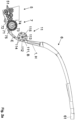
- Fig. 2 (a) shows schematically a section of a forage harvester 1 according to the invention.
- the feed unit 5, to which the shredding device 7 is arranged downstream, is visible. After shredding, the crop is conveyed into the conveyor channel 1.
- a conveying direction E of the crop is indicated by an arrow.
- the feed unit 5 has three pairs of conveyor and press rollers 51.
- the conveyor and press rollers 51 are designed to convey and press the crop.
- the conveyor and press rollers 51 are each rotated in a direction of rotation (not designated) about an axis of rotation (not designated).
- the direction of rotation of the conveyor and press rollers 51 of each pair is opposite.
- the crop is conveyed between the conveyor and press rollers 51 in the conveying direction E and thereby pressed. It is fed to the shredding device 7 with the conveyor and press rollers 51.
- the shredding device 7 is designed here as a chopping unit 7. In the following, the terms shredding device 7 and chopping unit are used synonymously.
- the chopping unit 7 includes a chopping drum 71 and a counter blade 72, between which the crop is cut.
- the chopping drum 71 is rotated about a chopping axis 73 in a chopping rotation direction 74 during operation of the forage harvester 10.
- chopping knives 75 are arranged evenly distributed in the chopping rotation direction 74 and are intended for cutting the crop.
- the chopping knives 75 rotate with the chopping drum 71 in the chopping direction of rotation 74. The crop comes into engagement with the chopping knives 75 and is cut between one of the chopping knives 75 and the shear bar 72.
- the conveying channel 1 is arranged downstream of the chopping drum 7 in the conveying direction E.
- the delivery channel 1 is shown here in a grass harvesting arrangement H.
- the conveying channel 1 arranged between the chopping unit 7 and the ejection pipe 6 has the post-accelerator 11.
- the post-accelerator 11 includes an acceleration rotor 111, which rotates about an acceleration axis 112 in an acceleration direction of rotation 113 during operation of the forage harvester 10.
- Acceleration blades 114 which are provided for conveying the crop, are arranged on the acceleration rotor 111 and are evenly distributed in the direction of acceleration rotation 113.
- the acceleration blades 114 rotate with the acceleration rotor 111 in the acceleration direction of rotation 113.
- the acceleration blades 114 pass through the conveying channel 1 to such an extent that the crop comes into engagement with the acceleration blades 114.
- the post-accelerator 11 is then in an acceleration position B.
- An impulse acting on the crop from an acceleration shovel 114 accelerates the crop sufficiently so that it can be conveyed through the ejection pipe 6 into the transport cart.
- the post-accelerator 11 has a rear wall 115 which is at a distance A from the acceleration rotor 111.
- the rear wall 115 is designed to be adjustable, so that the distance A can be changed. Alternatively, the distance can also be changed by adjusting the acceleration rotor 111 relative to the rear wall 115. A degree of acceleration of the crop by the post-accelerator 11 can be adjusted by adjusting the rear wall 115. This is possible by an operator of the forage harvester 10 manually or remotely on the control unit 22. To increase the acceleration performance, the distance is reduced. If less acceleration power is required, the distance can be increased, with less energy being required for the secondary accelerator 11. In order to operate the forage harvester 10 as efficiently as possible, the acceleration performance can be adapted to the currently prevailing harvest conditions.
- Changing the acceleration performance of the post-accelerator 11 can also be done automatically, for example depending on current harvest conditions, on the operating parameters of the forage harvester 10 or on the crop.
- the forage harvester 10 has a control unit 22 (see Fig. Fig. 1 ), which is set up to cause the automatic change.
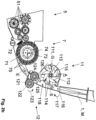
- Fig. 2 (b) In the section of the forage harvester 10 according to the invention shown, the feed unit 5, the chopping unit 7 and the conveying channel 1 are shown enlarged. The ejection tube 6 is not shown here. The conveying channel 1 is in contrast to the Fig. 2 (a) in a corn crop arrangement M.
- the conditioner 12 is arranged in the conveying channel 1.
- the conveyor channel 1 is then in the corn harvest configuration M.
- the conditioner 12 is used to break up the corn kernels.
- the conditioner 12 is not arranged in the conveying channel 1 in the grass harvesting arrangement H.
- the conditioner 12 comprises two cracker rollers 121, 124, each of which rotates about a cracker axis 122, 125, with a cracker rotation direction 123, 126 of the cracker rollers 121, 124 being opposite to one another.
- the corn will therefore conveyed between the cracker rollers 121, 124 during operation of the forage harvester 10.
- the shell of the corn kernels is broken open so that the starch inside the kernels is accessible.
- the corn kernels are already accelerated by the cracker rollers 121, 124. It has been shown that the acceleration performance through the cracker rollers 121, 124 is often sufficient to convey the crop through the ejection pipe 6 into the transport vehicle.
- the post-accelerator 11 is therefore often not required at all, in particular depending on, for example, harvest conditions such as humidity or operating conditions such as driving speed.
- the post-accelerator 11 of the forage harvester 10 is therefore adjusted here from an acceleration position B to a fan position G.
- the blower position G it is at least partially exposed to the conveyor channel 1, so that it releases it and the crop can flow through the conveyor channel 1 unhindered.
- the after-accelerator 11 is driven in the blower position G, so that it acts as a blower and generates an air flow S.
- the air flow is shown schematically here by arrows S in the direction of flow.
- the air flow S acts on the corn kernels. This accelerates, promotes and evens out their distribution.
- an outlet 118 is provided on the side of the post-accelerator 11 facing the delivery channel 1.
- Current guiding elements can also be provided for guiding the air flow S, in particular a direction of the air flow S.
- a strength of the air flow S can be changed by changing a rotation speed of the acceleration rotor 111 and/or changing the distance A between the rear wall 115 and the acceleration rotor 111.
- the forage harvester 12 has the control unit 22, which is set up to adjust the air flow S.
- the control unit 22 is set up to automatically adjust the air flow S.
- the amount of harvested material, particularly in the conveying channel 1 is recorded using sensors.
- the entry and exit into the crop can be recorded, for example, based on the operating parameters of the forage harvester 10 or by image capture on the front of the forage harvester 10.
- the post-accelerator 11, in particular its position G, B and/or the air flow S generated with it, can additionally or alternatively also be provided so that it can be adjusted by the operator on the operating unit 21.
Claims (12)
- Ramasseuse-hacheuse (10) comportant un canal de transfert (1) pour transférer le produit récolté qui, selon la direction de transfert (E) du produit récolté est en aval d'un dispositif broyeur (7) du produit,- le canal de transfert (1) comprenant un poste accélérateur (11) qui, en disposition de récolte d'herbe (H) est dans une position d'accélération (B) dans laquelle il vient dans le canal de transfert (1) pour accélérer le produit récolté et qui, en disposition de récolte de maïs (M) comporte un préparateur (12) dans le canal de transfert (1) qui ne vient pas dans le canal de transfert (1) pour la disposition de récolte d'herbe (H), ramasseuse-hacheuse caractérisée en ce quele post-accélérateur (11) dans la disposition de récolte de maïs (M), peut passer de la position d'accélération (B) à la position de soufflage (G) dans laquelle il est dégagé du canal de transfert (1) et fonctionne comme soufflante de sorte que la ramasseuse hacheuse (10) en disposition de récolte de maïs (M), comprend la soufflante servant à accélérer le produit récolté sans agir mécaniquement sur le produit récolté.
- Ramasseuse-hacheuse (10) selon la revendication 1,
caractérisée en ce que
le post-accélérateur (11) comprend un rotor d'accélération (111) avec des pales d'accélération (114) qui, en position d'accélération (B) coopèrent mécaniquement avec le produit récolté et qui, en position de soufflante (G) génèrent un courant d'air (S). - Ramasseuse-hacheuse (10) selon l'une des revendications précédentes,
caractérisée en ce qu'elle comprend
une unité de commande (21) pour modifier la veine d'air (S) générée par le post-accélérateur (11) en position de soufflante (G), notamment l'intensité et/ou la direction de la veine d'air (S). - Ramasseuse-hacheuse (10) selon l'une des revendications précédentes,
caractérisée en ce que
l'unité de commande (21) est conçue pour modifier en continu la veine d'air (S) ou par étapes. - Ramasseuse-hacheuse (10) selon l'une des revendications précédentes,
caractérisée en ce que
l'unité de commande (21) est conçue pour modifier la veine d'air (S) en fonction de la récolte et/ou selon des paramètres de fonctionnement de la ramasseuse hacheuse et/ou en fonction des conditions actuelles de récolte, notamment de la quantité actuelle récoltée, transférée. - Ramasseuse-hacheuse (10) selon l'une des revendications précédentes,
caractérisée en ce que
l'unité de commande (21) est conçue pour modifier la veine d'air (S) automatiquement ou en fonction des réglages actuels notamment demandés par l'opérateur. - Ramasseuse-hacheuse (10) selon l'une des revendications précédentes,
caractérisée en ce quel'unité de commande (21) est conçue pour intervenir sur le post-accélérateur (11) lors du passage et/ou du dégagement d'un état de récolte,* pour passer de la position d'accélération (B) à la position de soufflante (G) et/ou* adapter la veine d'air (S) en fonction de la quantité actuelle récoltée et/ou de la répartition du produit récolté. - Ramasseuse-hacheuse (10) selon l'une des revendications précédentes,
caractérisée en ce que
le post-accélérateur (11) peut être coulissé et/ou basculé de la position d'accélération (B) à la position de soufflante (G). - Ramasseuse-hacheuse (10) selon l'une des revendications précédentes,
caractérisée en ce que
le post-accélérateur (11) comporte en position de soufflante (G) au moins une sortie (118) sur le côté tourné vers le canal de transfert (1) et servant de passage pour la veine d'air (S). - Procédé de transfert de produit récolté notamment de maïs dans un canal de transfert (1) d'une ramasseuse-hacheuse (10) selon l'une des revendications précédentes,
caractérisé en ce que
on reçoit le produit de récolte au moins dans une disposition de récolte de maïs (M) dans un préparateur (12) dans le canal de transfert (1) par l'action d'une veine d'air (S) de la soufflante. - Procédé selon la revendication 10,
caractérisé en ce que
on règle la veine d'air (S) en fonction du produit récolté et/ou en fonction des paramètres de la ramasseuse-hacheuse (10) et/ou en fonction des conditions actuelles de récolte, par un réglage manuel ou automatique. - Ramasseuse-hacheuse selon l'une des revendications 10-11, caractérisée en ce que
on adapte l'intensité et/ou la direction de la veine d'air (S) en continu ou par échelons.
Applications Claiming Priority (1)
| Application Number | Priority Date | Filing Date | Title |
|---|---|---|---|
| DE102020002864.0A DE102020002864A1 (de) | 2020-05-13 | 2020-05-13 | Feldhäcksler mit einem Förderkanal zum Fördern von Erntegut und Verfahren zum Fördern des Ernteguts |
Publications (2)
| Publication Number | Publication Date |
|---|---|
| EP3909416A1 EP3909416A1 (fr) | 2021-11-17 |
| EP3909416B1 true EP3909416B1 (fr) | 2023-10-11 |
Family
ID=75904828
Family Applications (1)
| Application Number | Title | Priority Date | Filing Date |
|---|---|---|---|
| EP21173298.7A Active EP3909416B1 (fr) | 2020-05-13 | 2021-05-11 | Ramasseuse-hacheuse dotée d'un canal de transport permettant de transporter le produit de la récolte et procédé de transport du produit de la récolte |
Country Status (2)
| Country | Link |
|---|---|
| EP (1) | EP3909416B1 (fr) |
| DE (1) | DE102020002864A1 (fr) |
Family Cites Families (8)
| Publication number | Priority date | Publication date | Assignee | Title |
|---|---|---|---|---|
| DE10018825A1 (de) | 2000-04-15 | 2001-10-31 | Same Deutz Fahr Spa | Auswurfbeschleuniger für eine fahrbare Erntemaschine |
| DE10021657C2 (de) * | 2000-05-04 | 2002-08-01 | Krone Bernhard Gmbh Maschf | Erntemaschine, insbesondere selbstfahrender Feldhäcksler |
| DE10231316A1 (de) | 2002-07-10 | 2004-01-29 | Claas Selbstfahrende Erntemaschinen Gmbh | Verfahren und Vorrichtung zur automatischen Positionsveränderung des Nachbeschleunigungsorgans in einer landwirtschaftlichen Erntemaschine |
| DE10241788A1 (de) * | 2002-09-06 | 2004-04-01 | Claas Selbstfahrende Erntemaschinen Gmbh | Vorrichtung zum Zerkleinern von landwirtschaftlichem Erntegut |
| DE102007009587A1 (de) * | 2007-02-26 | 2008-08-28 | Claas Selbstfahrende Erntemaschinen Gmbh | Vorrichtung zur Einstellung der Position des Nachbeschleunigungsorgans in einer landwirtschaftlichen Erntemaschine |
| DE102011052945A1 (de) * | 2011-08-24 | 2013-02-28 | Claas Selbstfahrende Erntemaschinen Gmbh | Landwirtschaftliche Erntemaschine |
| DE102014106696A1 (de) * | 2014-05-13 | 2015-11-19 | Claas Selbstfahrende Erntemaschinen Gmbh | Feldhäcksler |
| DE102018104287A1 (de) * | 2018-02-26 | 2019-08-29 | Claas Selbstfahrende Erntemaschinen Gmbh | Feldhäcksler und Verfahren zum Betreiben eines Feldhäckslers |
-
2020
- 2020-05-13 DE DE102020002864.0A patent/DE102020002864A1/de active Pending
-
2021
- 2021-05-11 EP EP21173298.7A patent/EP3909416B1/fr active Active
Also Published As
| Publication number | Publication date |
|---|---|
| EP3909416A1 (fr) | 2021-11-17 |
| DE102020002864A1 (de) | 2021-11-18 |
Similar Documents
| Publication | Publication Date | Title |
|---|---|---|
| EP3662741B1 (fr) | Machine de travail agricole ainsi que procédé de fonctionnement d'une machine de travail agricole | |
| EP3298880B1 (fr) | Moissonneuse-batteuse dotée d'un système d'assistance du conducteur | |
| EP2452550B1 (fr) | Moissonneuse agricole | |
| EP3000303B1 (fr) | Moissonneuse-batteuse dote d'un systeme d'assistance du conducteur | |
| EP1972191B2 (fr) | Moissonneuse agricole | |
| EP1219164B1 (fr) | Procédé et dispositif pour convoyer des récoltes dans une machine agricole | |
| EP3395158B1 (fr) | Moissonneuse-batteuse | |
| DE102013108292A1 (de) | Mähdrescher mit einer Häckselvorrichtung | |
| EP1961288A1 (fr) | Dispositif destiné au réglage de la position de l'organe d'accélération ultérieure dans une moissonneuse agricole | |
| EP1219163B1 (fr) | Dispositif hacheur | |
| DE10063550B4 (de) | Mähdrescher mit Häckseleinrichtung | |
| EP3714675A1 (fr) | Procédé de fonctionnement d'une moissonneuse-batteuse ainsi que moissonneuse-batteuse autonome | |
| EP2218320A2 (fr) | Ramasseuse-hacheuse dotée d'un dispositif de traitement et de transport de marchandises à réglage couplé et son procédé de fonctionnement | |
| EP3520596B1 (fr) | Moissonneuse-batteuse | |
| EP3662737A1 (fr) | Moissonneuse-batteuse automotrice | |
| EP1396184B1 (fr) | Dispositif pour le broyage de produits de récolte | |
| DE102014102221A1 (de) | Verfahren und Steuerungssystem zum Betreiben eines Feldhäckslers sowie Feldhäcksler | |
| EP3300581B1 (fr) | Ensileuse comprenant un canal de traitement de récolte et une barre de mesure destinée à détecter une distribution transversale de la récolte dans le canal de traitement de récolte | |
| EP2796031B2 (fr) | Moissonneuse | |
| EP3714678B1 (fr) | Séparateur axial pour une moissonneuse-batteuse | |
| EP3884762A1 (fr) | Procédé de fonctionnement d'une moissonneuse-batteuse autonome ainsi que moissonneuse-batteuse autonome | |
| EP3909416B1 (fr) | Ramasseuse-hacheuse dotée d'un canal de transport permettant de transporter le produit de la récolte et procédé de transport du produit de la récolte | |
| EP1470749B1 (fr) | Système batteur-séparateur | |
| EP2853147A1 (fr) | Ramasseuse-hacheuse dotée d'un dispositif de post-accélération | |
| DE3436372C2 (fr) |
Legal Events
| Date | Code | Title | Description |
|---|---|---|---|
| PUAI | Public reference made under article 153(3) epc to a published international application that has entered the european phase |
Free format text: ORIGINAL CODE: 0009012 |
|
| STAA | Information on the status of an ep patent application or granted ep patent |
Free format text: STATUS: THE APPLICATION HAS BEEN PUBLISHED |
|
| AK | Designated contracting states |
Kind code of ref document: A1 Designated state(s): AL AT BE BG CH CY CZ DE DK EE ES FI FR GB GR HR HU IE IS IT LI LT LU LV MC MK MT NL NO PL PT RO RS SE SI SK SM TR |
|
| B565 | Issuance of search results under rule 164(2) epc |
Effective date: 20211011 |
|
| STAA | Information on the status of an ep patent application or granted ep patent |
Free format text: STATUS: REQUEST FOR EXAMINATION WAS MADE |
|
| 17P | Request for examination filed |
Effective date: 20220516 |
|
| RBV | Designated contracting states (corrected) |
Designated state(s): AL AT BE BG CH CY CZ DE DK EE ES FI FR GB GR HR HU IE IS IT LI LT LU LV MC MK MT NL NO PL PT RO RS SE SI SK SM TR |
|
| GRAP | Despatch of communication of intention to grant a patent |
Free format text: ORIGINAL CODE: EPIDOSNIGR1 |
|
| STAA | Information on the status of an ep patent application or granted ep patent |
Free format text: STATUS: GRANT OF PATENT IS INTENDED |
|
| P01 | Opt-out of the competence of the unified patent court (upc) registered |
Effective date: 20230517 |
|
| INTG | Intention to grant announced |
Effective date: 20230602 |
|
| GRAS | Grant fee paid |
Free format text: ORIGINAL CODE: EPIDOSNIGR3 |
|
| GRAA | (expected) grant |
Free format text: ORIGINAL CODE: 0009210 |
|
| STAA | Information on the status of an ep patent application or granted ep patent |
Free format text: STATUS: THE PATENT HAS BEEN GRANTED |
|
| AK | Designated contracting states |
Kind code of ref document: B1 Designated state(s): AL AT BE BG CH CY CZ DE DK EE ES FI FR GB GR HR HU IE IS IT LI LT LU LV MC MK MT NL NO PL PT RO RS SE SI SK SM TR |
|
| REG | Reference to a national code |
Ref country code: GB Ref legal event code: FG4D Free format text: NOT ENGLISH |
|
| REG | Reference to a national code |
Ref country code: CH Ref legal event code: EP |
|
| REG | Reference to a national code |
Ref country code: DE Ref legal event code: R096 Ref document number: 502021001664 Country of ref document: DE |
|
| REG | Reference to a national code |
Ref country code: IE Ref legal event code: FG4D Free format text: LANGUAGE OF EP DOCUMENT: GERMAN |
|
| REG | Reference to a national code |
Ref country code: LT Ref legal event code: MG9D |
|
| REG | Reference to a national code |
Ref country code: NL Ref legal event code: MP Effective date: 20231011 |
|
| PG25 | Lapsed in a contracting state [announced via postgrant information from national office to epo] |
Ref country code: NL Free format text: LAPSE BECAUSE OF FAILURE TO SUBMIT A TRANSLATION OF THE DESCRIPTION OR TO PAY THE FEE WITHIN THE PRESCRIBED TIME-LIMIT Effective date: 20231011 |
|
| PG25 | Lapsed in a contracting state [announced via postgrant information from national office to epo] |
Ref country code: GR Free format text: LAPSE BECAUSE OF FAILURE TO SUBMIT A TRANSLATION OF THE DESCRIPTION OR TO PAY THE FEE WITHIN THE PRESCRIBED TIME-LIMIT Effective date: 20240112 |
|
| PG25 | Lapsed in a contracting state [announced via postgrant information from national office to epo] |
Ref country code: IS Free format text: LAPSE BECAUSE OF FAILURE TO SUBMIT A TRANSLATION OF THE DESCRIPTION OR TO PAY THE FEE WITHIN THE PRESCRIBED TIME-LIMIT Effective date: 20240211 |
|
| PG25 | Lapsed in a contracting state [announced via postgrant information from national office to epo] |
Ref country code: LT Free format text: LAPSE BECAUSE OF FAILURE TO SUBMIT A TRANSLATION OF THE DESCRIPTION OR TO PAY THE FEE WITHIN THE PRESCRIBED TIME-LIMIT Effective date: 20231011 |
|
| PG25 | Lapsed in a contracting state [announced via postgrant information from national office to epo] |
Ref country code: ES Free format text: LAPSE BECAUSE OF FAILURE TO SUBMIT A TRANSLATION OF THE DESCRIPTION OR TO PAY THE FEE WITHIN THE PRESCRIBED TIME-LIMIT Effective date: 20231011 |
|
| PG25 | Lapsed in a contracting state [announced via postgrant information from national office to epo] |
Ref country code: LT Free format text: LAPSE BECAUSE OF FAILURE TO SUBMIT A TRANSLATION OF THE DESCRIPTION OR TO PAY THE FEE WITHIN THE PRESCRIBED TIME-LIMIT Effective date: 20231011 Ref country code: IS Free format text: LAPSE BECAUSE OF FAILURE TO SUBMIT A TRANSLATION OF THE DESCRIPTION OR TO PAY THE FEE WITHIN THE PRESCRIBED TIME-LIMIT Effective date: 20240211 Ref country code: GR Free format text: LAPSE BECAUSE OF FAILURE TO SUBMIT A TRANSLATION OF THE DESCRIPTION OR TO PAY THE FEE WITHIN THE PRESCRIBED TIME-LIMIT Effective date: 20240112 Ref country code: ES Free format text: LAPSE BECAUSE OF FAILURE TO SUBMIT A TRANSLATION OF THE DESCRIPTION OR TO PAY THE FEE WITHIN THE PRESCRIBED TIME-LIMIT Effective date: 20231011 Ref country code: BG Free format text: LAPSE BECAUSE OF FAILURE TO SUBMIT A TRANSLATION OF THE DESCRIPTION OR TO PAY THE FEE WITHIN THE PRESCRIBED TIME-LIMIT Effective date: 20240111 Ref country code: PT Free format text: LAPSE BECAUSE OF FAILURE TO SUBMIT A TRANSLATION OF THE DESCRIPTION OR TO PAY THE FEE WITHIN THE PRESCRIBED TIME-LIMIT Effective date: 20240212 |