EP1972002B1 - Vereinfachtes verfahren zum herstellen einer epitaxial gewachsenen struktur - Google Patents
Vereinfachtes verfahren zum herstellen einer epitaxial gewachsenen struktur Download PDFInfo
- Publication number
- EP1972002B1 EP1972002B1 EP06830329A EP06830329A EP1972002B1 EP 1972002 B1 EP1972002 B1 EP 1972002B1 EP 06830329 A EP06830329 A EP 06830329A EP 06830329 A EP06830329 A EP 06830329A EP 1972002 B1 EP1972002 B1 EP 1972002B1
- Authority
- EP
- European Patent Office
- Prior art keywords
- crystalline
- substrate
- array
- elements
- network
- Prior art date
- Legal status (The legal status is an assumption and is not a legal conclusion. Google has not performed a legal analysis and makes no representation as to the accuracy of the status listed.)
- Not-in-force
Links
Images


Classifications
-
- H—ELECTRICITY
- H10—SEMICONDUCTOR DEVICES; ELECTRIC SOLID-STATE DEVICES NOT OTHERWISE PROVIDED FOR
- H10P—GENERIC PROCESSES OR APPARATUS FOR THE MANUFACTURE OR TREATMENT OF DEVICES COVERED BY CLASS H10
- H10P10/00—Bonding of wafers, substrates or parts of devices
- H10P10/12—Bonding of semiconductor wafers or semiconductor substrates to semiconductor wafers or semiconductor substrates
- H10P10/128—Bonding of semiconductor wafers or semiconductor substrates to semiconductor wafers or semiconductor substrates by direct semiconductor to semiconductor bonding
-
- C—CHEMISTRY; METALLURGY
- C30—CRYSTAL GROWTH
- C30B—SINGLE-CRYSTAL GROWTH; UNIDIRECTIONAL SOLIDIFICATION OF EUTECTIC MATERIAL OR UNIDIRECTIONAL DEMIXING OF EUTECTOID MATERIAL; REFINING BY ZONE-MELTING OF MATERIAL; PRODUCTION OF A HOMOGENEOUS POLYCRYSTALLINE MATERIAL WITH DEFINED STRUCTURE; SINGLE CRYSTALS OR HOMOGENEOUS POLYCRYSTALLINE MATERIAL WITH DEFINED STRUCTURE; AFTER-TREATMENT OF SINGLE CRYSTALS OR A HOMOGENEOUS POLYCRYSTALLINE MATERIAL WITH DEFINED STRUCTURE; APPARATUS THEREFOR
- C30B25/00—Single-crystal growth by chemical reaction of reactive gases, e.g. chemical vapour-deposition growth
- C30B25/02—Epitaxial-layer growth
- C30B25/18—Epitaxial-layer growth characterised by the substrate
-
- C—CHEMISTRY; METALLURGY
- C30—CRYSTAL GROWTH
- C30B—SINGLE-CRYSTAL GROWTH; UNIDIRECTIONAL SOLIDIFICATION OF EUTECTIC MATERIAL OR UNIDIRECTIONAL DEMIXING OF EUTECTOID MATERIAL; REFINING BY ZONE-MELTING OF MATERIAL; PRODUCTION OF A HOMOGENEOUS POLYCRYSTALLINE MATERIAL WITH DEFINED STRUCTURE; SINGLE CRYSTALS OR HOMOGENEOUS POLYCRYSTALLINE MATERIAL WITH DEFINED STRUCTURE; AFTER-TREATMENT OF SINGLE CRYSTALS OR A HOMOGENEOUS POLYCRYSTALLINE MATERIAL WITH DEFINED STRUCTURE; APPARATUS THEREFOR
- C30B33/00—After-treatment of single crystals or homogeneous polycrystalline material with defined structure
-
- H—ELECTRICITY
- H10—SEMICONDUCTOR DEVICES; ELECTRIC SOLID-STATE DEVICES NOT OTHERWISE PROVIDED FOR
- H10P—GENERIC PROCESSES OR APPARATUS FOR THE MANUFACTURE OR TREATMENT OF DEVICES COVERED BY CLASS H10
- H10P14/00—Formation of materials, e.g. in the shape of layers or pillars
- H10P14/20—Formation of materials, e.g. in the shape of layers or pillars of semiconductor materials
- H10P14/27—Formation of materials, e.g. in the shape of layers or pillars of semiconductor materials using selective deposition, e.g. simultaneous growth of monocrystalline and non-monocrystalline semiconductor materials
- H10P14/271—Formation of materials, e.g. in the shape of layers or pillars of semiconductor materials using selective deposition, e.g. simultaneous growth of monocrystalline and non-monocrystalline semiconductor materials characterised by the preparation of substrate for selective deposition
-
- H—ELECTRICITY
- H10—SEMICONDUCTOR DEVICES; ELECTRIC SOLID-STATE DEVICES NOT OTHERWISE PROVIDED FOR
- H10P—GENERIC PROCESSES OR APPARATUS FOR THE MANUFACTURE OR TREATMENT OF DEVICES COVERED BY CLASS H10
- H10P14/00—Formation of materials, e.g. in the shape of layers or pillars
- H10P14/20—Formation of materials, e.g. in the shape of layers or pillars of semiconductor materials
- H10P14/27—Formation of materials, e.g. in the shape of layers or pillars of semiconductor materials using selective deposition, e.g. simultaneous growth of monocrystalline and non-monocrystalline semiconductor materials
- H10P14/276—Lateral overgrowth
- H10P14/278—Pendeoepitaxy
-
- H—ELECTRICITY
- H10—SEMICONDUCTOR DEVICES; ELECTRIC SOLID-STATE DEVICES NOT OTHERWISE PROVIDED FOR
- H10P—GENERIC PROCESSES OR APPARATUS FOR THE MANUFACTURE OR TREATMENT OF DEVICES COVERED BY CLASS H10
- H10P14/00—Formation of materials, e.g. in the shape of layers or pillars
- H10P14/20—Formation of materials, e.g. in the shape of layers or pillars of semiconductor materials
- H10P14/29—Formation of materials, e.g. in the shape of layers or pillars of semiconductor materials characterised by the substrates
- H10P14/2901—Materials
- H10P14/2902—Materials being Group IVA materials
- H10P14/2905—Silicon, silicon germanium or germanium
-
- H—ELECTRICITY
- H10—SEMICONDUCTOR DEVICES; ELECTRIC SOLID-STATE DEVICES NOT OTHERWISE PROVIDED FOR
- H10P—GENERIC PROCESSES OR APPARATUS FOR THE MANUFACTURE OR TREATMENT OF DEVICES COVERED BY CLASS H10
- H10P14/00—Formation of materials, e.g. in the shape of layers or pillars
- H10P14/20—Formation of materials, e.g. in the shape of layers or pillars of semiconductor materials
- H10P14/29—Formation of materials, e.g. in the shape of layers or pillars of semiconductor materials characterised by the substrates
- H10P14/2924—Structures
- H10P14/2925—Surface structures
-
- H—ELECTRICITY
- H10—SEMICONDUCTOR DEVICES; ELECTRIC SOLID-STATE DEVICES NOT OTHERWISE PROVIDED FOR
- H10P—GENERIC PROCESSES OR APPARATUS FOR THE MANUFACTURE OR TREATMENT OF DEVICES COVERED BY CLASS H10
- H10P14/00—Formation of materials, e.g. in the shape of layers or pillars
- H10P14/20—Formation of materials, e.g. in the shape of layers or pillars of semiconductor materials
- H10P14/34—Deposited materials, e.g. layers
- H10P14/3402—Deposited materials, e.g. layers characterised by the chemical composition
-
- H—ELECTRICITY
- H10—SEMICONDUCTOR DEVICES; ELECTRIC SOLID-STATE DEVICES NOT OTHERWISE PROVIDED FOR
- H10P—GENERIC PROCESSES OR APPARATUS FOR THE MANUFACTURE OR TREATMENT OF DEVICES COVERED BY CLASS H10
- H10P14/00—Formation of materials, e.g. in the shape of layers or pillars
- H10P14/20—Formation of materials, e.g. in the shape of layers or pillars of semiconductor materials
- H10P14/38—Formation of materials, e.g. in the shape of layers or pillars of semiconductor materials characterised by treatments done after the formation of the materials
-
- H—ELECTRICITY
- H10—SEMICONDUCTOR DEVICES; ELECTRIC SOLID-STATE DEVICES NOT OTHERWISE PROVIDED FOR
- H10P—GENERIC PROCESSES OR APPARATUS FOR THE MANUFACTURE OR TREATMENT OF DEVICES COVERED BY CLASS H10
- H10P50/00—Etching of wafers, substrates or parts of devices
- H10P50/60—Wet etching
- H10P50/64—Wet etching of semiconductor materials
- H10P50/642—Chemical etching
Definitions
- the present invention relates to a method for producing an epitaxial structure.
- epitaxy is a crystal growth technique used to form, on the surface of a crystalline host substrate, layers whose crystalline axes are in relation to the crystalline axes of the host substrate. Heteroepitaxy is called if the deposited material is of a different chemical species than that of the host substrate. Substrates thus coated are of great interest for the manufacture of semiconductor, optical or optoelectronic devices. The optimization of the crystalline growth of the layers makes it possible to improve the performance of these devices.
- the production of a heteroepitaxy deposit on a substrate gives rise to dislocations of mesh cleavage (known by the Anglo-Saxon name of misfit) from a certain thickness of deposited layer called critical thickness. This thickness depends on the difference in the mesh parameters between the epitaxial material and that of the host substrate. We can refer for example to the article of JW Matthews and AE Blakeslee, "Defects in epitaxial multilayers" Journal of Crystal Growth No. 27, pp. 118-125, 1974 .
- the mesh parameters are the lateral dimensions of the elementary cell describing the crystalline material.
- one method consists in first having epitaxially grown columns (sometimes called islands in the literature) spaced apart from one another on the host substrate.
- the advantage is that the epitaxial material growing in the form of columns can relax its stress on the free surface of the host substrate. For example, in the case of growth in compression of a column on a substrate, the column will gradually flake out, its diameter increasing to relax the stress within the deposited material. Conversely, in the case of growth in extension of a column, it will gradually shrink, its diameter tending to decrease to relax its stress. Simultaneously with stress relaxation, there is a lateral growth which tends to permanently increase the diameter of the columns. Thus, by dashing, the columns eventually meet to form a continuous layer.
- the deposition conditions can be modified to promote lateral growth and coalescence, i.e., welding of the contacting columns. If the spacing of the columns is appropriate, as the columns meet, the epitaxial material will have relaxed all or part of its stress and will have found all the part of its natural mesh parameter.
- the level of relaxation can be quantified by the rate of relaxation corresponding to the ratio between the level of stress of departure and that obtained after epitaxy in the absence of appearance of defects.
- One technique used to obtain the columns consists in delimiting on the surface of the host substrate localized growth germs, these growth seeds having a suitable surface which corresponds to that of the base of the columns. For this we can have on the substrate of the substrate a growth mask, this mask having openings exposing the host substrate. The bare substrate at the bottom of the openings forms the seeds of growth.
- a growth mask for this we can have on the substrate of the substrate a growth mask, this mask having openings exposing the host substrate. The bare substrate at the bottom of the openings forms the seeds of growth.
- the thin layer is etched by lithography and ion etching (known by the acronym RIE for reactive ionic etching) to locally expose the substrate and thus delimit in the thin layer of the cells forming the growth seeds.
- RIE reactive ionic etching
- Epitaxy can then be started to grow the epitaxial material from the seeds. Since the material to be epitaxially deposited only at the level of the growth germs, the growth takes the form of columns.
- the problems caused by this method are that it requires a lithography step to engrave the mask or the crystalline layer and thus define the growth seeds.
- these growth seeds must be made at the nanoscale, their typical size being between one and a few tens of nanometers, and must be distributed very evenly over the surface of the host substrate, the distance between these seeds being from the order of ten to a few hundred nanometers.
- the present invention aims at providing a method for producing a structure grown by nanoscale growth of columns without having to resort to a nanoscale lithography step.
- This substrate is economically obtained and can have a large surface area.
- the position and geometry of the columns are obtained with great precision.
- the present invention is a process for producing an epitaxial structure consisting of depositing a material by columnar epitaxial growth on a crystalline face of a substrate, to continue the deposition until the columns meet and lead to a continuous layer. It consists in providing the face of the substrate with a periodic network of nanoscale protrusions, each protrusion having a bearing zone for a column, and being obtained directly or indirectly from a lattice of crystalline defects and / or constraint fields created within a crystalline zone located in the vicinity of a bonding interface between two elements comprising crystalline material and having crystal lattices offset in rotation and / or in flexion and / or having a disagreement of parameters mesh at the interface, able to condition the period of the network of projections, the period of the network, the height of the projections and the size of their support zone being adjusted so that the continuous layer has a critical thickness greater than that obtained during an epitaxy performed in the absence of projections.
- the period of the grating, the height of the protrusions and the size of their support zone are adjusted so that the epitaxially deposited material has found its natural mesh parameter at the moment when the columns meet.
- the substrate the face of which is provided with the network of projections, can be made from the two bonded elements, by thinning one of the elements until a surface relief corresponding to the network of crystalline defects and / or stress fields appears, this relief then forming the network of projections, this network of projections being supported by the other element.
- Thinning may comprise at least one step selected from mechanical abrasion, chemical abrasion, rectification, sacrificial treatment.
- the method may further comprise a step of processing the array of projections so as to adjust the height and / or the size of the bearing area of the projections and / or to modify the mesh parameter of the material constituting the projections.
- the step of processing the network of projections may comprise an implantation step.
- the step of thinning and / or treatment of the network of projections may comprise at least one etching step and / or electrochemical etching and / or mechanical etching and / or ion etching and / or photochemical attack and / or depot.
- the step of thinning and / or treatment of the network of projections may include the provision of a thermal budget, in various atmospheres, oxidizing or reducing.
- At least two crystalline structures can be parts, these two parts contributing to the formation of the bonding interface.
- the two parts preferably have their crystal lattices offset in rotation and / or in flexion by a predetermined angle.
- the crystalline structure preferably has registration marks which are reported in both parts during sampling, these registration marks being used to adjust the offset angle.
- At least one of the elements is a composite substrate formed of a stack of a support, a stop layer at the thinning of the support and at least one crystalline layer.
- the thinning step preferably relates to the composite substrate.
- the composite substrate may be an SOI substrate.
- the portion taken from the composite substrate comprises at least the crystalline layer.
- the bonding can be done by molecular adhesion.
- the substrate whose face is provided with the network of projections may be made by duplication of a mother substrate whose one face comprises a network of projections at the nanometric scale, the mother substrate being obtained from the two bonded elements and by at least one step of thinning one of the elements leading directly or indirectly to a revelation of the network of crystalline defects and / or stress fields, this network of crystalline defects and / or stress fields forming the network of projections.
- Duplication can be done by nanoimprinting from a complementary mold of the parent substrate.
- the mold it can be obtained by nanoimpression from the mother substrate.
- the present invention also relates to an epitaxial structure comprising columns (4) of epitaxial material flaring so as to meet and form a continuous layer.
- Each column rests on a support zone of a protrusion of a periodic network of protrusions at the nanoscale which is provided with a face of a substrate, these protrusions coming directly or indirectly from a lattice of crystalline defects and / or stress fields, the protrusions of the grating having a period, a height and a size of support zone adjusted so that the continuous layer has a critical thickness greater than that obtained during an epitaxy performed in the absence of projections.
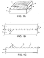
- FIGS. 1A to 1G show different steps of a first example of a process for producing an epitaxial structure according to the invention.
- the method which is the subject of the invention consists in producing the epitaxial structure by starting the deposition of the material to be epitaxially grown by columnar growth on a crystalline free surface 1 of a substrate 2 provided with a network of projections 3 on a nanometric scale such as illustrated on the figure 1D .
- These protrusions have a size of the order of 1 to a few tens of nanometers, typically 20 nanometers.
- This substrate 2 may be called a nanostructured substrate.
- the columns 4 are supported on these projections 3 and more precisely on an end zone 35 of the protrusions further called thereafter bearing zone.
- bearing zones 35 form the base of the columns 4. This deposition continues, as in the prior art, until the columns 4 join together and form a uniform continuous layer 5.
- the projections have dimensions and the network of projections a period adapted so that the material that is deposited has a desired relaxation rate of its constraints, for example the largest possible, at the time of coalescence, that is to say say at the time of the welding of the columns 4 between them.
- dimension is meant their height 36 and the size of the bearing zone 35.
- the uniform continuous layer 5 which is formed when the epitaxial deposition is continued will therefore also have some or all of the stresses relaxed. It will have a critical thickness greater than that of the layer that would have been obtained by conventional epitaxy without prior columnar growth.
- the projections 3 are obtained at the nanoscale. It may be for example substantially parallelepipedal volumes whose dimensions are of the order of a few tens of nanometers.
- This angle of rotation offset ⁇ is known as the Anglo-Saxon angle of "twist", this name will be used thereafter.
- the Figure 1A shows the contacting of the two elements 11, 12 and illustrates the "twist" angle ⁇ and the crystal lattices of the two elements 11, 12. This molecular bonding is done so that interatomic bonds are established between the two elements 11, 12 and cause, due to the angular offset, the formation of a periodic lattice of crystalline defects and / or stress fields 14 within a crystalline zone 16 located at near the bonding interface 15.
- the Figure 1B illustrates in section the structure obtained after the bonding and illustrates the network of crystalline defects and / or stress fields 14 obtained.
- the collage is done hot or cold.
- the seal will preferably be reinforced by a heat treatment to obtain this network of crystalline defects and / or stress fields 14. These crystalline defects may be dislocations.
- the crystalline zone 16 has a small thickness (a few tens of nanometers) and is located around the interface 15. This network 14 of crystalline defects and / or stress fields is at the origin of the network of projections at the nanoscale .
- the period of the lattice of crystalline defects and / or of stress fields depends on the "twist" angle ⁇ of the crystal lattices of the two elements 11, 12. It is possible to refer to the Figure 1A .
- one of the two assembled elements 11 12 is thinned, for example by rectification, by mechanical or chemical abrasion, so that the presence of the lattice 14 of crystalline defects and / or stress fields causes the level of the freed surface of protruding reliefs and recesses.
- the depressions may correspond to the crystalline defects and the projections to the crystalline material of the crystalline zone 16 or vice versa. It is on these projections 3 and more particularly on their end zone or support 35 that we will grow the columns.
- the figure 1C which shows the network of projections that has been induced.
- the structured surface obtained can be located in the first element 11, straddling the two elements 11, 12 as illustrated in FIG. figure 1C or in the second element 12 if the element 11 has been completely eliminated.
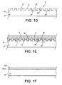
- An optional surface treatment may then be performed to further accentuate the surface relief as illustrated in the figure 1D and adjust the height 36 of the protrusions 3 and the size of their bearing zone 35.
- a chemical bath can be used to selectively attack the crystalline defects 14, without attacking their vicinity.
- a nanostructured substrate is thus obtained, that is to say provided with a network of projections 3 separated by recesses 6, these recesses and these projections being dimensioned on the nanometric scale.
- the "twist" angle between the two elements 11, 12 conditions the period of the lattice of crystalline defects and / or of the stress field as previously seen and thus also the period 38 between the projections 3.
- this period 38 With silicon as crystalline material, it is possible to modulate and control very finely this period 38, for example between a few nanometers and a few hundred nanometers with a precision of the order of a few tenths of nanometers if the adjustment of the "twist" angle takes place with a precision of the order of a hundredth of a degree.
- This accuracy can be obtained as taught in the patent application FR-A1-2 819 099 by taking the two elements 11, 12 in the same initial structure and providing this structure beforehand with one or more registration marks before the separation of the two elements. It is then sufficient to precisely control the relative angular positions of the two elements before assembling them and this is done through the registration marks. This method will be described later in figures 2 .
- This period 38 is one of the elements which makes it possible to control the moment when the columns will meet according to the thickness of the epitaxial material. It depends on the angle of "twist".
- the element which is not thinned, in the example element 12 could be formed of a stack with a film 12.1 of crystalline material covering a stop layer etching 12.2 as shown in FIG. figure 1F .
- the assembly of this element with the other can be done as described above.
- the barrier layer 12.2 may be made for example of silicon oxide, silicon nitride or amorphous silicon.
- the film 12.1 may be chosen from one of the materials mentioned below as a crystalline host material, for example made of silicon.
- the advantage of using an element 12 as illustrated in FIG. figure 1F is that during the treatment, we will locally expose the barrier layer 12.2, at the level of the recesses 6 and that thus will obtain two different materials on the surface, advantageously only one will allow the epitaxial growth.
- a second advantage is that it can independently control the height and the lateral dimensions of the projections.
- the stop layer 12.2 may be only partially attacked or not attacked.
- the attack may be a dry or wet attack, chemical, ionic, electrochemical, photochemical, thermal, under reducing or oxidizing atmosphere.
- the attack can for example have a very fast speed low in the stop layer 12.2 compared to that which exists in the crystalline material to adjust the lateral dimensions of the projections 7. It can be referred to the figure 1G .
- the barrier layer may be etched selectively vis-à-vis the material of the film 12.1 as well as the underlying layer.
- the epitaxial growth is in columnar form on the bearing zone 35 of the protrusions 3, but of course also in the depressions. It is sought by adjusting the dimensions of the projections so that the hollows are not completely filled with material. With projections 3 sufficiently high and close, for example with a height 36 of the order of 10 nanometers and a spacing 37 of the order of 3 nanometers, the columnar growth is sufficiently decoupled from the growth in the recesses 6 to allow the relaxation of the material forming the columns 4 and the formation of the uniform continuous layer whose stresses are relaxed.
- a continuous layer 5 of thickness and crystalline quality required can be obtained.
- the critical thickness 39 for this layer 5 is always greater than that which would have been obtained with a host substrate that would not be structured. If we exceed this critical thickness 39, the defect rate in the layer will be lower than that which would have been obtained for a layer of the same thickness without structuring the host substrate.
- the crystalline host material may be chosen from silicon Si, germanium Ge and gallium arsenide GaAs. , silicon carbide SiC, indium phosphide InP, sapphire, diamond, zirconia, magnesium oxide MgO, these materials being taken alone or in combination.
- the epitaxially deposited material may be chosen from silicon Si, germanium Ge, gallium nitride GaN, diamond, silicon carbide SiC, indium phosphide InP, gallium arsenide GaAs, arsenide d indium InAs, silicon-germanium Si x Ge 1-x , III-V compounds for example of InGaAs type or compounds II-VI for example of CdTe type, these materials being taken alone or in combination.
- the material of the epitaxial layer in its continuous part is in general different from that of the receiving substrate 2.
- the variation may or may not be linear.
- the epitaxial growth can be continued by germanium. AT equivalent critical thickness for the germanium layer, it will require a much smaller thickness for the epitaxial layer of Si x Ge 1-x with variable x on the bearing zones 35, than if the epitaxy of Si x Ge 1-x (with x variable) was done on a substrate that was not structured.
- An advantage of the method according to the invention over the prior art is that there is no longer need for a lithography step or mask in which it was difficult to engrave openings with a density and dimensions such as that these openings lead to an epitaxial layer whose stresses are well relaxed.
- the method of the invention since it is possible to obtain a greater density of protrusions than the density of openings etched in the mask, and this with a controlled period very precisely and since it is possible to obtain projections having a zone of support that is smaller than that of the openings of the mask, it will be easier to obtain a better relaxation of the stresses of the epitaxial layer.
- the epitaxial layer 5 formed may have constraints as minimized as possible and therefore a relaxation rate of its constraints as large as possible.
- this layer can be done without plastic relaxation and thus avoiding the formation of defects that appear traditionally because of this plastic relaxation. Nevertheless, it will be possible to choose if it is desired to exceed the critical thickness: a layer having defects will then be obtained but in a smaller quantity than a layer that would have been obtained without the invention. It is possible that the The material of the epitaxial layer has a very different mesh parameter, for example different from several percent, of the mesh parameter of the substrate material 12 having the network of projections.
- Another advantage of the method of the invention is that the formation of projections is collectively with very small dimensions, very accurately and with great regularity, regardless of the size of the assembled elements. This process applies with the same constraints both to substrates of 100 millimeters in diameter and to larger substrates, for example 150, 200 or 300 millimeters in diameter. These dimensions are standard industrial sizes of silicon substrates. With the method of the prior art, mask etching used lithographic techniques which are longer and more expensive with large substrates than with smaller ones and which are not always available for small substrates. for example less than 50 millimeters.
- one of the elements is included in a composite substrate formed of a support, a stop layer at the thinning of the support and at least the crystalline layer forming the element to be assembled.
- It may be for example a semiconductor on insulator substrate, known under the name SOI.
- An SOI substrate may comprise two layers of semiconductor material located on either side of an insulating layer. One of the layers of semiconductor material is thinner than the other. The thicker layer corresponds to the support of the composite substrate, the layer of insulation to the stop layer to the thinning of the support, the layer less thick to the element to be assembled. It is by the thinnest layer that the semiconductor on insulator substrate will be assembled to the other element.
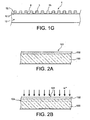
- a base substrate 100 of crystalline semiconductor material for example silicon, having a free face 101 oriented in the ⁇ 001> direction.
- This substrate may have a diameter of 100 millimeters, but a smaller or larger substrate of 150, 200 or even 300 millimeters in diameter could be used.
- the choice of this orientation ⁇ 001> makes it possible to obtain a network of projections having a symmetry of order of 4. It is of course possible to use a base substrate whose surface would have another crystalline orientation, for example for example, the crystal orientation ⁇ 111> which would give the network of projections a symmetry of order 3.
- This substrate 100 will be treated so as to be able to take two parts having crystalline surfaces which will be glued to each other thereafter.
- This oxide layer 102 may have a thickness of about 400 nanometers. This step is illustrated on the Figure 2A .
- the oxide layer 102 will subsequently serve as a stop layer for thinning.
- the base substrate 100 will then be weakened by means of implanted ions, for example hydrogen ions or any other gaseous species, capable of generating a buried embrittlement zone and capable of subsequently inducing a fracture at this zone. fragilization.
- This weakening zone 104 will take the form of a plane located in the silicon of the base substrate 100, under the oxide layer 102 at a distance of the order of the implantation depth.
- the implantation is made from the free surface 101 of the oxide layer 102.
- the implantation energy may be, for example, for a silicon substrate, about 76 keV and the hydrogen ion dose is about 6.10. 16 atoms / cm 2 . Under these conditions, for an oxide layer 102 of 400 nanometers, the embrittlement zone 104 is about 760 nanometers from the free surface of the oxide layer 102. Reference is made to FIG. Figure 2B .
- One or more registration marks 105 are then produced, for example by photolithography and chemical, ionic or other etching in the oxide layer 102 and in the underlying semiconductor of the base substrate 100, these locating marks 105 encroaching in the base substrate 100 beyond the embrittlement zone 104 with respect to the oxide layer 102. Other methods of etching these registration marks could be used, for example by means of a laser .
- the registration marks 105 could pass completely through the base substrate 100. Reference can be made to the Figure 2C which illustrates these registration marks 105.
- These registration marks 105 can be configured as explained in the patent application. FR-A-2,819,099 and take the form of graduated scales such as rapporteurs. The graduations can indicate for example the degrees, the tenths of degrees, the hundredths of degrees or the thousandths of degrees. When there are two registration marks, they can be diametrically opposed on the base substrate 100.
- auxiliary substrate 106 for example silicon. This assembly is done by the face carrying the oxide layer 102.
- the assembly method can be a hydrophilic molecular bonding.
- a fracture is then caused along the plane of the weakened zone 104, for example by a heat treatment, for example at 500 ° C. for one hour.
- This heat treatment also has the advantage to strengthen molecular membership.
- one of the elements 110 is a semiconductor-on-insulator substrate and in this case silicon-on-insulator, it is formed of the stack of the auxiliary substrate 106, the oxide layer 102 and the a crystalline silicon thin film 107 taken from the base substrate 100 by virtue of the fracture.
- the other element 108 corresponds to what remains of the base substrate 100.
- the two elements 108, 110 are both provided with registration marks 105 and have a crystalline portion 107, 108 which comes from the base substrate 100.
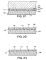
- the element 110 which is in the example is of the SOI substrate type, can be subjected to an annealing, oxidation and polishing treatment on the side of the thin film 107 which has the registration marks 105 without of course making disappear the marking marks 105. It is arranged that at the end of treatment, the thin silicon film 107 retains a thickness for example of the order of 100 nanometers.
- the other element 108 which, in the example, is solid can be subjected to a polishing of its face bearing the registration marks 105 so as to obtain a polished surface compatible with the subsequent bonding, without, of course, removing the marks of 105.
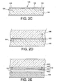
- the element 110 formed by the semiconductor-on-insulator substrate will be thinned. It is of course possible, alternatively, especially when the starting substrate is composite as described in figures 4 to thin the substrate 200 from the support 201 to the stop layer 202 as shown in FIG. figure 4D .
- the thinning of the element 110 consists in keeping all or part of the thin film 107 taken from the base substrate 100 at the 2D figure .
- the auxiliary substrate 106 which formed the thickest silicon part of the SOI substrate 110, will initially be eliminated. This elimination may be carried out, for example, by a mechanical method known to the man of the invention. art then by a chemical method using for example TMAH (trimethylammonium hydroxide).
- TMAH trimethylammonium hydroxide
- the oxide layer 102 is then removed by etching, for example by means of an aqueous solution of hydrofluoric acid HF.
- the hydrofluoric acid concentration can be 10%.
- the thin film 107 is then thinned, its thickness may, for example, be reduced to less than 20 nanometers.
- This thinning may consist of chemical etching and / or thermal oxidation followed by etching, the etching being possible for example by means of an aqueous solution of hydrofluoric acid.
- the sequence of the thermal oxidation followed by the chemical attack corresponds to a sacrificial treatment.
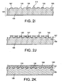
- the free surface 111 of the thinned film 107 does not reveal the presence of the lattice of crystalline defects and / or stress fields 114.
- the structure represented in FIG. figure 2H The next step, illustrated in figure 2I is to treat the thinned film 107 so that its free face 111 reveals the presence of the lattice of crystalline defects and / or stress fields 114 around the bonding interface 115.
- This treatment can be a chemical attack that preferentially attacks the areas of stress.
- a surface is obtained with a network of projections 130 at the nanoscale.
- This chemical attack can be carried out using aqueous chemical solutions based on hydrofluoric acid and chromium trioxide CrO 3 / HF; hydrofluoric acid and nitric acid HNO 3 / HF; of dichromate ions and hydrofluoric acid Cr 2 O 7-- / HF. It is possible to add to these solutions acetic acid and / or an alcohol such as ethanol or propanol and / or ammonia.
- the revelation step can be completed by other surface treatment steps such as other chemical etchings, ion etches (RIE). , oxidation and deoxidation, electrochemical attacks, photochemical, deposits of material etc ........ It may for example deposit germanium, typically the equivalent of a film of 1 nanometer.
- the deposit will be mainly on the support zones 135 which are silicon in our example. It will then be possible to increase the height of the projections 130 by selectively etching the silicon with respect to the germanium.
- the germanium thin film located on the bearing zones 135 may optionally be removed before the columnar epitaxy step.
- protrusions 130 of about 10 nanometers in height, two adjacent protrusions 130 being spaced apart by about 4 nanometers and the period of the grating being about 20 nanometers. It is specified that the period corresponds to the interval formed by a support zone and the spacing that follows or precedes it.
- the revelation step may consist of a thermal budget contribution.
- This thermal budget can be provided in the form of at least one annealing, possibly in the presence of a particular gas or under vacuum.
- This thermal budget is intended to cause a change in the topology of the free surface 111 of the thin film 107 by revealing projections 130 and hollows which depend on the topology of the lattice of crystalline defects and / or stress fields 114 which is in the vicinity of the interface 115, that is to say which is buried with respect to the free surface 111 of the thin film 107.
- Other methods can be used to reveal the lattice of crystal defects and / or stress fields 114 such as the introduction of chemical species into the thin film 107 or into the other element 108, for example by diffusion or ion implantation.
- the introduction of chemical species can coexist with the contribution of the thermal budget, this introduction can take place before and / or after and / or during the contribution of the thermal budget.
- the introduced chemical species may be gold, copper, titanium, aluminum, or a dopant, for example boron for silicon.
- the chemical species introduced are located at the level of defects and / or zones of maximum stress. It is then possible to reveal the network of projections to use for example a selective etching step.
- the revelation can also be done by etching and / or electrochemical and / or ionic and / or photochemical and / or mechanical thinned element (thin film 107 or 108 element). In the same way this attack can coexist with the contribution of the thermal budget, it can take place before and / or after and / or during the contribution of the thermal budget.
- the attack step (s) can be carried out under various oxidizing or reducing atmospheres.
- the epitaxy may be for example a gas phase epitaxy or a molecular epitaxy (known by the acronym MBE for molecular beam epitaxy).
- MBE molecular beam epitaxy
- columns 140 are formed on the support zone 135 of the projections as illustrated in FIG. figure 2J .
- the deposit continues and the columns 140 widen, increase their diameter and eventually meet.
- the continuous layer 150 then takes shape as on the figure 2K .
- the material which is deposited on the projections 130 will relax its stress by modifying the diameter of the columns 140.
- the measurement of the mesh parameters indicates the stress relaxation rate of the deposited material.
- the geometric parameters of the columns 140 that is to say their base section, will be very precisely controlled. their spacing and from the size of the bearing zone 135 of the projections 130, their height 136 and their spacing 137.
- the continuous epitaxial layer 150 obtained may be transferred to another substrate with or without a crystallographic relationship with it.
- the other substrate that will receive the epitaxial continuous layer may be for example plastic, glass, another crystalline material, for example, semiconductor such as silicon, oxide of a material such as silica or even carbide of a semiconductor material such as silicon carbide.
- This transfer can be done by implantation of gaseous species capable of providing a buried fragile zone and then fracture at this zone, for example by thermal and / or mechanical treatment as described in the patent application.
- FR-A-2,681,472 are examples of gaseous species capable of providing a buried fragile zone and then fracture at this zone, for example by thermal and / or mechanical treatment as described in the patent application.
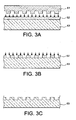
- NIL nanoimprint lithography
- This technique consists in molding the network of protrusions of the substrate 61 (called the parent substrate) by a layer, for example, of resin 62 carried by a substrate 63 as illustrated on FIG. figure 3A .
- This postponement can be done, for example, by hot embossing or ultraviolet exposure ( figure 3B ).
- the substrate 63 which is for example made of silicon, is then etched using the openwork resin layer 62 as a mask.
- the etching can be an ion etching (RIE).
- RIE ion etching
- a crystalline substrate 64 is then covered with a layer of, for example, polymeric resin 65.
- the mold cavity 63 is left in the polymer layer 65, for example, by hot embossing or ultraviolet exposure, as shown on FIG. the 3D and 3E figures .
- the crystalline substrate 64 is then etched through the imprint left in the polymer resin layer 65 as shown in FIG. figure 3F .
- a replica of the mother substrate 61 having a network of projections substantially identical to that of the parent substrate is then obtained. This technique of nanoimprint lithography is described for example in the article Replication of sub-40nm gap nanoelectrodes over an 8-in. Substrate by nanoimprint lithography Tallal J. et al, Microelectronic engineering, 2005, vol.78-79 pages 676 to 681 .
Landscapes
- Chemical & Material Sciences (AREA)
- Engineering & Computer Science (AREA)
- Crystallography & Structural Chemistry (AREA)
- Materials Engineering (AREA)
- Metallurgy (AREA)
- Organic Chemistry (AREA)
- Chemical Kinetics & Catalysis (AREA)
- General Chemical & Material Sciences (AREA)
- Crystals, And After-Treatments Of Crystals (AREA)
- Recrystallisation Techniques (AREA)
- Auxiliary Devices For Music (AREA)
Claims (21)
- Verfahren zur Herstellung einer epitaxierten Struktur, darin bestehend, durch epitaxales Säulenwachstum ein Material auf einer kristallinen Vorderseite eines Substrats (2) abzuscheiden und die Abscheidung solange fortzusetzen, bis die Säulen (4) zusammenwachsen und eine kontinuierliche Schicht (5) bilden,
dadurch gekennzeichnet, dass es darin besteht, auf der Vorderseite des Substrats ein periodisches Gitter von Erhebungen (3) im nanometrischen Maßstab zu erzeugen, wobei jede Erhebung (3) eine Stützzone (35) für eine Säule (4) darstellt und direkt oder indirekt hergestellt wird mittels eines Kristallfehler- und/oder Spannungsfeldergitters, erzeugt im Innern einer kristallinen Zone (16), die sich in der Nähe einer Klebungsschnittfläche (15) zwischen zwei Elementen (11, 12) befindet, die kristallines Material umfassen und rotations- und/oder flexionsversetzt sind und dabei an der Schnittfläche eine Nichtübereinstimmung von Maschenparametorn aufweisen, die fähig sind, die Periode (38) des Gitters von Erhebungen (3) zu konditionieren, wobei die Periode (38) des Gitters, die Höhe (36) der Erhebungen und die Größe ihrer Stützzone (35) so adjustiert werden, dass die kontinuierliche Schicht (40) eine kritische Dicke (39) aufweist, die größer als diejenige ist, die man bei einer Epitaxie ohne das Vorhandensein der Erhebungen erhält. - Verfahren nach Anspruch 1, bei dem das durch Epitaxie abgeschiedene Material einen natürlichen Maschenparameter hat, dadurch gekennzeichnet, dass die Periode (38) des Gitters, die Höhe (36) der Erhebungen und die Größe ihrer Stützzone (35) so adjustiert werden, dass das durch Epitaxie abgeschiedene Material in dem Moment, wo die Säulen zusammenwachsen, seinen natürlichen Maschenparameter wiedergewonnen hat.
- Verfahren nach einem der Ansprüche 1 oder 2, dadurch gekennzeichnet, dass es darin besteht, das Substrat (2), dessen Seite ein Gitter von Erhebungen (3) aufweist, aus zwei zusammengeklebten Elementen (11, 12) zu realisieren, indem man eines der Elemente (11) dünnt, bis ein dem Kristallfehler- und/oder Spannungsfeldergitter entsprechendes Oberflächenrelief erscheint, wobei dieses Relief dann das Erhebungen-Gitter (3) bildet und das andere Element (12) dieses Erhebungen-Gitter trägt.
- Verfahren nach Anspruch 3, dadurch gekennzeichnet, dass die Dünnung wenigstens einen Schritt umfasst, der gebildet wird durch eine mechanische Abrasion, eine chemische Abrasion, ein Rektifizieren bzw. Feinschleifen, eine Opferungsbehandlung.
- Verfahren nach einem der Ansprüche 1 bis 4, dadurch gekennzeichnet, dass es außerdem umfasst: einen Schritt zur Behandlung des Erhebungen-Gitters, um die Höhe (36) und/oder die Größe der Stützzone (35) der Erhebungen (3) zu adjustieren und/oder den Maschenparameter des die Erhebungen (3) bildenden Materials zu modifizieren.
- Verfahren nach Anspruch 5, dadurch gekennzeichnet, dass der Behandlungsschritt des Erhebungen-Gitters (3) einen Implantationsschritt umfasst.
- Verfahren nach einem der Ansprüche 3 bis 5, dadurch gekennzeichnet, dass der Dünnungs- und/oder Behandlungsschritt des Erhebungen-Gitters (3) wenigstens einen Schritt des Typs chemischer Angriff und/oder elektrochemischer Angriff und/oder mechanischer Angriff und/oder ionischer Angriff und/oder photochemischer Angriff und/oder eine Abscheidung umfasst, unter diversen oxidierenden oder reduzierenden Atmosphären.
- Verfahren nach einem der Ansprüche 3 bis 5, dadurch gekennzeichnet, dass der Dünnungs- und/oder Behandlungsschritt des Erhebungen-Gitters (3) die Unterstützung bzw. Hilfe eines Wärmebudgets umfasst.
- Verfahren nach einem der Ansprüche 1 bis 8, dadurch gekennzeichnet, dass man zur Bildung der Elemente einer selben kristallinen Struktur (100) wenigstens zwei Teile (108, 107) entnimmt, wobei diese beiden Teile zur Bildung der Klebungsschnittfläche (115) beitragen.
- Verfahren nach Anspruch 9, dadurch gekennzeichnet, dass beim Zusammenkleben der beiden Teile deren Kristallgitter um einen vorherbestimmten Winkel (θ) rotations- und/oder flexionsversetzt sind.
- Verfahren nach Anspruch 10, dadurch gekennzeichnet, dass die kristalline Struktur Bezugsmarken (105) umfasst, die bei der Entnahme in die beiden Teile (108, 107) übertragen werden, wobei diese Marken benutzt werden, um den Versetzungswinkel (θ) zu adjustieren.
- Verfahren nach einem der Ansprüche 1 bis 11, dadurch gekennzeichnet, dass wenigstens eines der Elemente (110) ein Verbundsubstrat ist, gebildet durch einen Stapel aus einem Träger (106), einer Trägerdünnungs-Stoppschicht (102) und wenigstens einer kristallinen Schicht (107).
- Verfahren nach Anspruch 12, dadurch gekennzeichnet, dass der Dünnungsschritt das Verbundsubstrat (110) betrifft.
- Verfahren nach einem der Ansprüche 12 oder 13, dadurch gekennzeichnet, dass das Verbundsubstrat ein SOI-Substrat ist.
- Verfahren nach einem der Ansprüche 12 bis 14, dadurch gekennzeichnet, dass der entnommene Teil (107) wenigstens eine kristalline Schicht umfasst.
- Verfahren nach einem der Ansprüche 1 bis 15, dadurch gekennzeichnet, dass die Klebung eine molekulare Adhäsion ist.
- Verfahren nach einem der Ansprüche 1 bis 16, dadurch gekennzeichnet, dass die Zusammensetzung des abgeschiedenen Materials während der Abscheidung durch Epitaxie variiert.
- Verfahren nach Anspruch 1, dadurch gekennzeichnet, dass das Substrat (64), dessen Vorderseite das Erhebungen-Gitter aufweist, realisiert wird durch die Duplikation eines Muttersubstrats (61), bei dem eine Seite ein Gitter von Erhebungen im nanometrischen Bereich umfasst, wobei das Muttersubstrat (61) durch die beiden zusammengeklebten Elemente und durch wenigstens einen Schritt zur Dünnung eines der Elemente realisiert wird, was direkt oder indirekt zu einer Entwicklung des Kristallfehler-und/oder Spannungsfeldergitters führt, wobei dieses Kristallfehler- und/oder Spannungsfeldergitter das Erhebungen-Gitter bildet.
- Verfahren nach Anspruch 18, dadurch gekennzeichnet, dass man die Duplikation durch Nanoprägung mittels einer Komplementärform (63) des Substrats (61) realisiert.
- Verfahren nach Anspruch 19, dadurch gekennzeichnet, dass man die Form (63) durch Nanoprägung erhält, ausgehend von dem Muttersubstrat (61).
- Epitaxierte Struktur mit Säulen (4) aus epitaxiertem Material, die sich so ausweiten, dass sie eine kontinuierliche Schicht (5) bilden, dadurch gekennzeichnet, dass jede Säule (4) auf einer Stützzone (35) einer Erhebung (3) eines periodischen Gitters von Erhebungen im nanometrischen Bereich ruht, mit denen eine Seite eines Substrats (2) versehen ist, wobei diese Erhebungen (3) direkt oder indirekt durch ein Kristallfehler-und/oder Spannungsfeldergitter verursacht werden und die Erhebungen (3) dabei eine Höhe (36) und eine Größe der Stützzone (35) aufweisen, die so adjustiert sind, dass die kontinuierliche Schicht (5) eine kritische Dicke (39) hat, die größer als diejenige ist, die man bei einer Epitaxie ohne das Vorhandensein der Erhebungen erhält.
Applications Claiming Priority (2)
| Application Number | Priority Date | Filing Date | Title |
|---|---|---|---|
| FR0554107A FR2895419B1 (fr) | 2005-12-27 | 2005-12-27 | Procede de realisation simplifiee d'une structure epitaxiee |
| PCT/EP2006/069263 WO2007074027A1 (fr) | 2005-12-27 | 2006-12-04 | Procede de realisation simplifiee d'une structure epitaxiee |
Publications (2)
| Publication Number | Publication Date |
|---|---|
| EP1972002A1 EP1972002A1 (de) | 2008-09-24 |
| EP1972002B1 true EP1972002B1 (de) | 2009-04-08 |
Family
ID=36295113
Family Applications (1)
| Application Number | Title | Priority Date | Filing Date |
|---|---|---|---|
| EP06830329A Not-in-force EP1972002B1 (de) | 2005-12-27 | 2006-12-04 | Vereinfachtes verfahren zum herstellen einer epitaxial gewachsenen struktur |
Country Status (7)
| Country | Link |
|---|---|
| US (1) | US7579259B2 (de) |
| EP (1) | EP1972002B1 (de) |
| JP (1) | JP2009521391A (de) |
| AT (1) | ATE428184T1 (de) |
| DE (1) | DE602006006225D1 (de) |
| FR (1) | FR2895419B1 (de) |
| WO (1) | WO2007074027A1 (de) |
Families Citing this family (24)
| Publication number | Priority date | Publication date | Assignee | Title |
|---|---|---|---|---|
| FR2903810B1 (fr) * | 2006-07-13 | 2008-10-10 | Commissariat Energie Atomique | Procede de nanostructuration de la surface d'un substrat |
| US7557002B2 (en) | 2006-08-18 | 2009-07-07 | Micron Technology, Inc. | Methods of forming transistor devices |
| US7989322B2 (en) * | 2007-02-07 | 2011-08-02 | Micron Technology, Inc. | Methods of forming transistors |
| TWI366252B (en) * | 2008-08-06 | 2012-06-11 | Jer Liang Yeh | Substrate with high fracture strength, structure for increasing the fracture strength of a substrate and the method thereof |
| FR2937797B1 (fr) * | 2008-10-28 | 2010-12-24 | S O I Tec Silicon On Insulator Tech | Procede de fabrication et de traitement d'une structure de type semi-conducteur sur isolant, permettant de deplacer des dislocations, et structure correspondante |
| US20100187572A1 (en) * | 2009-01-26 | 2010-07-29 | Cho Hans S | Suspended mono-crystalline structure and method of fabrication from a heteroepitaxial layer |
| WO2011069242A1 (en) * | 2009-12-09 | 2011-06-16 | Cooledge Lighting Inc. | Semiconductor dice transfer-enabling apparatus and method for manufacturing transfer-enabling apparatus |
| US20110151588A1 (en) * | 2009-12-17 | 2011-06-23 | Cooledge Lighting, Inc. | Method and magnetic transfer stamp for transferring semiconductor dice using magnetic transfer printing techniques |
| US8334152B2 (en) * | 2009-12-18 | 2012-12-18 | Cooledge Lighting, Inc. | Method of manufacturing transferable elements incorporating radiation enabled lift off for allowing transfer from host substrate |
| FR2955853B1 (fr) | 2010-02-02 | 2012-03-09 | Inst Nat Sciences Appliq | Procede de fabrication de nano-batonnets epitaxies sur un support, nano-batonnets epitaxies obtenus par un tel procede et support d'enregistrement de donnees numeriques |
| JP2011192752A (ja) * | 2010-03-12 | 2011-09-29 | Stanley Electric Co Ltd | 半導体素子の製造方法 |
| TWI442455B (zh) * | 2010-03-29 | 2014-06-21 | S O I 矽科技絕緣體工業公司 | Iii-v族半導體結構及其形成方法 |
| US8138068B2 (en) * | 2010-08-11 | 2012-03-20 | International Business Machines Corporation | Method to form nanopore array |
| FR2964048B1 (fr) * | 2010-08-30 | 2012-09-21 | Commissariat Energie Atomique | Procédé de réalisation d'un film, par exemple monocristallin, sur un support en polymère |
| KR101235239B1 (ko) | 2011-05-20 | 2013-02-21 | 서울대학교산학협력단 | 반도체 박막 구조 및 그 형성 방법 |
| US8927398B2 (en) * | 2013-01-04 | 2015-01-06 | International Business Machines Corporation | Group III nitrides on nanopatterned substrates |
| CN106661759B (zh) * | 2014-08-11 | 2020-04-07 | 住友电气工业株式会社 | 金刚石复合体、衬底、金刚石、包括金刚石的工具、以及制造金刚石的方法 |
| CN104681411A (zh) * | 2015-01-29 | 2015-06-03 | 江苏能华微电子科技发展有限公司 | 用于生长外延晶体的半导体衬底及半导体器件 |
| FR3040108B1 (fr) | 2015-08-12 | 2017-08-11 | Commissariat Energie Atomique | Procede de fabrication d'une structure semi-conductrice avec collage direct temporaire exploitant une couche poreuse |
| US9577042B1 (en) * | 2015-08-13 | 2017-02-21 | Globalfoundries Inc. | Semiconductor structure with multilayer III-V heterostructures |
| US10556317B2 (en) | 2016-03-03 | 2020-02-11 | P.R. Hoffman Machine Products Inc. | Polishing machine wafer holder |
| KR101828293B1 (ko) | 2016-07-26 | 2018-03-23 | (재)한국나노기술원 | 진공증착에 의한 나노구조체 패턴 형성방법, 이를 이용한 센서 소자의 제조방법 및 이에 의해 제조된 센서 소자 |
| WO2022074903A1 (ja) * | 2020-10-06 | 2022-04-14 | 住友電気工業株式会社 | 炭化珪素基板、炭化珪素単結晶基板および炭化珪素半導体装置の製造方法 |
| TWI768957B (zh) | 2021-06-08 | 2022-06-21 | 合晶科技股份有限公司 | 複合基板及其製造方法 |
Family Cites Families (7)
| Publication number | Priority date | Publication date | Assignee | Title |
|---|---|---|---|---|
| US5158907A (en) * | 1990-08-02 | 1992-10-27 | At&T Bell Laboratories | Method for making semiconductor devices with low dislocation defects |
| TW279275B (de) * | 1993-12-27 | 1996-06-21 | Sharp Kk | |
| FR2766620B1 (fr) | 1997-07-22 | 2000-12-01 | Commissariat Energie Atomique | Realisation de microstructures ou de nanostructures sur un support |
| US6380108B1 (en) * | 1999-12-21 | 2002-04-30 | North Carolina State University | Pendeoepitaxial methods of fabricating gallium nitride semiconductor layers on weak posts, and gallium nitride semiconductor structures fabricated thereby |
| FR2815121B1 (fr) | 2000-10-06 | 2002-12-13 | Commissariat Energie Atomique | Procede de revelation de defauts cristallins et/ou de champs de contraintes a l'interface d'adhesion moleculaire de deux materiaux solides |
| FR2819099B1 (fr) * | 2000-12-28 | 2003-09-26 | Commissariat Energie Atomique | Procede de realisation d'une structure empilee |
| US7186630B2 (en) * | 2002-08-14 | 2007-03-06 | Asm America, Inc. | Deposition of amorphous silicon-containing films |
-
2005
- 2005-12-27 FR FR0554107A patent/FR2895419B1/fr not_active Expired - Fee Related
-
2006
- 2006-12-04 WO PCT/EP2006/069263 patent/WO2007074027A1/fr not_active Ceased
- 2006-12-04 AT AT06830329T patent/ATE428184T1/de not_active IP Right Cessation
- 2006-12-04 US US12/158,191 patent/US7579259B2/en not_active Expired - Fee Related
- 2006-12-04 EP EP06830329A patent/EP1972002B1/de not_active Not-in-force
- 2006-12-04 JP JP2008547929A patent/JP2009521391A/ja active Pending
- 2006-12-04 DE DE602006006225T patent/DE602006006225D1/de active Active
Also Published As
| Publication number | Publication date |
|---|---|
| FR2895419A1 (fr) | 2007-06-29 |
| US7579259B2 (en) | 2009-08-25 |
| JP2009521391A (ja) | 2009-06-04 |
| DE602006006225D1 (de) | 2009-05-20 |
| US20080272396A1 (en) | 2008-11-06 |
| WO2007074027A1 (fr) | 2007-07-05 |
| FR2895419B1 (fr) | 2008-02-22 |
| ATE428184T1 (de) | 2009-04-15 |
| EP1972002A1 (de) | 2008-09-24 |
Similar Documents
| Publication | Publication Date | Title |
|---|---|---|
| EP1972002B1 (de) | Vereinfachtes verfahren zum herstellen einer epitaxial gewachsenen struktur | |
| EP2175478B1 (de) | Verfahren zum Übertragen eines Dünnfilms mit einem Einschlüsse erzeugenden Schritt | |
| EP1346402B1 (de) | Verfahren zur herstellung einer stapelstruktur | |
| EP1576658B1 (de) | Herstellungsverfahren für gemischte substrate und dadurch hergestellte struktur | |
| EP1354346A1 (de) | Verfahren zur herstellung eines dünnfilms unter einbringung gasförmiger spezien | |
| EP1938362B1 (de) | Verfahren zum herstellen eines dünnfilmelements | |
| FR2938117A1 (fr) | Procede d'elaboration d'un substrat hybride ayant une couche continue electriquement isolante enterree | |
| FR2924273A1 (fr) | Procede de moderation de deformation | |
| FR2906078A1 (fr) | Procede de fabrication d'une structure micro-technologique mixte et une structure ainsi obtenue | |
| EP1397835B1 (de) | Verfahren zum kontrollieren der kristallinen orientierung einer verbundstruktur | |
| EP3948940B1 (de) | Verfahren zur übertragung von blöcken von einem donorsubstrat auf ein empfängersubstrat | |
| EP2226678B1 (de) | Verfahren zur Herstellung einer Nanoimprintform | |
| EP1803683B1 (de) | Verfahren zur Bearbeitung von geordneten Nanostrukturen | |
| EP4085478B1 (de) | Verfahren zur herstellung einer verbundstruktur mit einer dünnen monokristallinen schicht auf einem trägersubstrat | |
| FR2937797A1 (fr) | Procede de fabrication et de traitement d'une structure de type semi-conducteur sur isolant, permettant de deplacer des dislocations, et structure correspondante | |
| FR2869459A1 (fr) | Realignement entre niveaux apres une etape d'epitaxie. | |
| FR3071098A1 (fr) | Procede de realisation d'un element d'un dispositif microelectronique | |
| EP3446328A1 (de) | Mehrschichtige fotorezeptorvorrichtung mit schichten mit unterschiedlichen gitterparametern | |
| FR3036845A1 (fr) | Procede de transfert d'une couche d'un substrat monocristallin | |
| FR2915317A1 (fr) | Procede de realisation d'un film mince vertical, en particulier pour la realisation d'un canal d'un transistor finfet. |
Legal Events
| Date | Code | Title | Description |
|---|---|---|---|
| PUAI | Public reference made under article 153(3) epc to a published international application that has entered the european phase |
Free format text: ORIGINAL CODE: 0009012 |
|
| 17P | Request for examination filed |
Effective date: 20080610 |
|
| AK | Designated contracting states |
Kind code of ref document: A1 Designated state(s): AT BE BG CH CY CZ DE DK EE ES FI FR GB GR HU IE IS IT LI LT LU LV MC NL PL PT RO SE SI SK TR |
|
| GRAP | Despatch of communication of intention to grant a patent |
Free format text: ORIGINAL CODE: EPIDOSNIGR1 |
|
| DAX | Request for extension of the european patent (deleted) | ||
| GRAS | Grant fee paid |
Free format text: ORIGINAL CODE: EPIDOSNIGR3 |
|
| GRAA | (expected) grant |
Free format text: ORIGINAL CODE: 0009210 |
|
| AK | Designated contracting states |
Kind code of ref document: B1 Designated state(s): AT BE BG CH CY CZ DE DK EE ES FI FR GB GR HU IE IS IT LI LT LU LV MC NL PL PT RO SE SI SK TR |
|
| REG | Reference to a national code |
Ref country code: GB Ref legal event code: FG4D Free format text: NOT ENGLISH |
|
| REG | Reference to a national code |
Ref country code: CH Ref legal event code: EP |
|
| REG | Reference to a national code |
Ref country code: IE Ref legal event code: FG4D |
|
| REF | Corresponds to: |
Ref document number: 602006006225 Country of ref document: DE Date of ref document: 20090520 Kind code of ref document: P |
|
| PG25 | Lapsed in a contracting state [announced via postgrant information from national office to epo] |
Ref country code: SI Free format text: LAPSE BECAUSE OF FAILURE TO SUBMIT A TRANSLATION OF THE DESCRIPTION OR TO PAY THE FEE WITHIN THE PRESCRIBED TIME-LIMIT Effective date: 20090408 |
|
| NLV1 | Nl: lapsed or annulled due to failure to fulfill the requirements of art. 29p and 29m of the patents act | ||
| REG | Reference to a national code |
Ref country code: IE Ref legal event code: FD4D |
|
| PG25 | Lapsed in a contracting state [announced via postgrant information from national office to epo] |
Ref country code: ES Free format text: LAPSE BECAUSE OF FAILURE TO SUBMIT A TRANSLATION OF THE DESCRIPTION OR TO PAY THE FEE WITHIN THE PRESCRIBED TIME-LIMIT Effective date: 20090719 Ref country code: LT Free format text: LAPSE BECAUSE OF FAILURE TO SUBMIT A TRANSLATION OF THE DESCRIPTION OR TO PAY THE FEE WITHIN THE PRESCRIBED TIME-LIMIT Effective date: 20090408 Ref country code: FI Free format text: LAPSE BECAUSE OF FAILURE TO SUBMIT A TRANSLATION OF THE DESCRIPTION OR TO PAY THE FEE WITHIN THE PRESCRIBED TIME-LIMIT Effective date: 20090408 Ref country code: PT Free format text: LAPSE BECAUSE OF FAILURE TO SUBMIT A TRANSLATION OF THE DESCRIPTION OR TO PAY THE FEE WITHIN THE PRESCRIBED TIME-LIMIT Effective date: 20090908 Ref country code: AT Free format text: LAPSE BECAUSE OF FAILURE TO SUBMIT A TRANSLATION OF THE DESCRIPTION OR TO PAY THE FEE WITHIN THE PRESCRIBED TIME-LIMIT Effective date: 20090408 |
|
| PG25 | Lapsed in a contracting state [announced via postgrant information from national office to epo] |
Ref country code: NL Free format text: LAPSE BECAUSE OF FAILURE TO SUBMIT A TRANSLATION OF THE DESCRIPTION OR TO PAY THE FEE WITHIN THE PRESCRIBED TIME-LIMIT Effective date: 20090408 Ref country code: LV Free format text: LAPSE BECAUSE OF FAILURE TO SUBMIT A TRANSLATION OF THE DESCRIPTION OR TO PAY THE FEE WITHIN THE PRESCRIBED TIME-LIMIT Effective date: 20090408 Ref country code: IS Free format text: LAPSE BECAUSE OF FAILURE TO SUBMIT A TRANSLATION OF THE DESCRIPTION OR TO PAY THE FEE WITHIN THE PRESCRIBED TIME-LIMIT Effective date: 20090808 Ref country code: SE Free format text: LAPSE BECAUSE OF FAILURE TO SUBMIT A TRANSLATION OF THE DESCRIPTION OR TO PAY THE FEE WITHIN THE PRESCRIBED TIME-LIMIT Effective date: 20090708 Ref country code: PL Free format text: LAPSE BECAUSE OF FAILURE TO SUBMIT A TRANSLATION OF THE DESCRIPTION OR TO PAY THE FEE WITHIN THE PRESCRIBED TIME-LIMIT Effective date: 20090408 |
|
| PG25 | Lapsed in a contracting state [announced via postgrant information from national office to epo] |
Ref country code: RO Free format text: LAPSE BECAUSE OF FAILURE TO SUBMIT A TRANSLATION OF THE DESCRIPTION OR TO PAY THE FEE WITHIN THE PRESCRIBED TIME-LIMIT Effective date: 20090408 Ref country code: DK Free format text: LAPSE BECAUSE OF FAILURE TO SUBMIT A TRANSLATION OF THE DESCRIPTION OR TO PAY THE FEE WITHIN THE PRESCRIBED TIME-LIMIT Effective date: 20090408 Ref country code: IE Free format text: LAPSE BECAUSE OF FAILURE TO SUBMIT A TRANSLATION OF THE DESCRIPTION OR TO PAY THE FEE WITHIN THE PRESCRIBED TIME-LIMIT Effective date: 20090408 Ref country code: EE Free format text: LAPSE BECAUSE OF FAILURE TO SUBMIT A TRANSLATION OF THE DESCRIPTION OR TO PAY THE FEE WITHIN THE PRESCRIBED TIME-LIMIT Effective date: 20090408 Ref country code: CZ Free format text: LAPSE BECAUSE OF FAILURE TO SUBMIT A TRANSLATION OF THE DESCRIPTION OR TO PAY THE FEE WITHIN THE PRESCRIBED TIME-LIMIT Effective date: 20090408 |
|
| PLBE | No opposition filed within time limit |
Free format text: ORIGINAL CODE: 0009261 |
|
| STAA | Information on the status of an ep patent application or granted ep patent |
Free format text: STATUS: NO OPPOSITION FILED WITHIN TIME LIMIT |
|
| PG25 | Lapsed in a contracting state [announced via postgrant information from national office to epo] |
Ref country code: SK Free format text: LAPSE BECAUSE OF FAILURE TO SUBMIT A TRANSLATION OF THE DESCRIPTION OR TO PAY THE FEE WITHIN THE PRESCRIBED TIME-LIMIT Effective date: 20090408 |
|
| 26N | No opposition filed |
Effective date: 20100111 |
|
| PG25 | Lapsed in a contracting state [announced via postgrant information from national office to epo] |
Ref country code: BG Free format text: LAPSE BECAUSE OF FAILURE TO SUBMIT A TRANSLATION OF THE DESCRIPTION OR TO PAY THE FEE WITHIN THE PRESCRIBED TIME-LIMIT Effective date: 20090708 |
|
| BERE | Be: lapsed |
Owner name: COMMISSARIAT A L'ENERGIE ATOMIQUE Effective date: 20091231 |
|
| PG25 | Lapsed in a contracting state [announced via postgrant information from national office to epo] |
Ref country code: MC Free format text: LAPSE BECAUSE OF NON-PAYMENT OF DUE FEES Effective date: 20100701 |
|
| PG25 | Lapsed in a contracting state [announced via postgrant information from national office to epo] |
Ref country code: GR Free format text: LAPSE BECAUSE OF FAILURE TO SUBMIT A TRANSLATION OF THE DESCRIPTION OR TO PAY THE FEE WITHIN THE PRESCRIBED TIME-LIMIT Effective date: 20090709 Ref country code: BE Free format text: LAPSE BECAUSE OF NON-PAYMENT OF DUE FEES Effective date: 20091231 |
|
| PG25 | Lapsed in a contracting state [announced via postgrant information from national office to epo] |
Ref country code: LU Free format text: LAPSE BECAUSE OF NON-PAYMENT OF DUE FEES Effective date: 20091204 |
|
| PG25 | Lapsed in a contracting state [announced via postgrant information from national office to epo] |
Ref country code: HU Free format text: LAPSE BECAUSE OF FAILURE TO SUBMIT A TRANSLATION OF THE DESCRIPTION OR TO PAY THE FEE WITHIN THE PRESCRIBED TIME-LIMIT Effective date: 20091009 |
|
| REG | Reference to a national code |
Ref country code: CH Ref legal event code: PL |
|
| PG25 | Lapsed in a contracting state [announced via postgrant information from national office to epo] |
Ref country code: TR Free format text: LAPSE BECAUSE OF FAILURE TO SUBMIT A TRANSLATION OF THE DESCRIPTION OR TO PAY THE FEE WITHIN THE PRESCRIBED TIME-LIMIT Effective date: 20090408 |
|
| PG25 | Lapsed in a contracting state [announced via postgrant information from national office to epo] |
Ref country code: CY Free format text: LAPSE BECAUSE OF FAILURE TO SUBMIT A TRANSLATION OF THE DESCRIPTION OR TO PAY THE FEE WITHIN THE PRESCRIBED TIME-LIMIT Effective date: 20090408 |
|
| PG25 | Lapsed in a contracting state [announced via postgrant information from national office to epo] |
Ref country code: CH Free format text: LAPSE BECAUSE OF NON-PAYMENT OF DUE FEES Effective date: 20101231 Ref country code: LI Free format text: LAPSE BECAUSE OF NON-PAYMENT OF DUE FEES Effective date: 20101231 |
|
| PGFP | Annual fee paid to national office [announced via postgrant information from national office to epo] |
Ref country code: DE Payment date: 20121207 Year of fee payment: 7 |
|
| PGFP | Annual fee paid to national office [announced via postgrant information from national office to epo] |
Ref country code: IT Payment date: 20121213 Year of fee payment: 7 Ref country code: GB Payment date: 20121219 Year of fee payment: 7 |
|
| PGFP | Annual fee paid to national office [announced via postgrant information from national office to epo] |
Ref country code: FR Payment date: 20130123 Year of fee payment: 7 |
|
| REG | Reference to a national code |
Ref country code: DE Ref legal event code: R119 Ref document number: 602006006225 Country of ref document: DE |
|
| GBPC | Gb: european patent ceased through non-payment of renewal fee |
Effective date: 20131204 |
|
| REG | Reference to a national code |
Ref country code: DE Ref legal event code: R119 Ref document number: 602006006225 Country of ref document: DE Effective date: 20140701 |
|
| REG | Reference to a national code |
Ref country code: FR Ref legal event code: ST Effective date: 20140829 |
|
| PG25 | Lapsed in a contracting state [announced via postgrant information from national office to epo] |
Ref country code: DE Free format text: LAPSE BECAUSE OF NON-PAYMENT OF DUE FEES Effective date: 20140701 |
|
| PG25 | Lapsed in a contracting state [announced via postgrant information from national office to epo] |
Ref country code: GB Free format text: LAPSE BECAUSE OF NON-PAYMENT OF DUE FEES Effective date: 20131204 Ref country code: FR Free format text: LAPSE BECAUSE OF NON-PAYMENT OF DUE FEES Effective date: 20131231 |
|
| PG25 | Lapsed in a contracting state [announced via postgrant information from national office to epo] |
Ref country code: IT Free format text: LAPSE BECAUSE OF NON-PAYMENT OF DUE FEES Effective date: 20131231 |
|
| PG25 | Lapsed in a contracting state [announced via postgrant information from national office to epo] |
Ref country code: IT Free format text: LAPSE BECAUSE OF NON-PAYMENT OF DUE FEES Effective date: 20131204 |