EP1970087A2 - Inhalierer und Ausgabekopfeinheit, die an dem Inhalierer befestigt werden kann - Google Patents
Inhalierer und Ausgabekopfeinheit, die an dem Inhalierer befestigt werden kann Download PDFInfo
- Publication number
- EP1970087A2 EP1970087A2 EP08152317A EP08152317A EP1970087A2 EP 1970087 A2 EP1970087 A2 EP 1970087A2 EP 08152317 A EP08152317 A EP 08152317A EP 08152317 A EP08152317 A EP 08152317A EP 1970087 A2 EP1970087 A2 EP 1970087A2
- Authority
- EP
- European Patent Office
- Prior art keywords
- ejection
- ejection head
- medicine
- inhaler
- head unit
- Prior art date
- Legal status (The legal status is an assumption and is not a legal conclusion. Google has not performed a legal analysis and makes no representation as to the accuracy of the status listed.)
- Granted
Links
- 239000003814 drug Substances 0.000 claims abstract description 80
- 230000002093 peripheral effect Effects 0.000 claims description 3
- 230000007246 mechanism Effects 0.000 claims description 2
- 230000000717 retained effect Effects 0.000 claims 1
- 238000001514 detection method Methods 0.000 description 17
- NOESYZHRGYRDHS-UHFFFAOYSA-N insulin Chemical compound N1C(=O)C(NC(=O)C(CCC(N)=O)NC(=O)C(CCC(O)=O)NC(=O)C(C(C)C)NC(=O)C(NC(=O)CN)C(C)CC)CSSCC(C(NC(CO)C(=O)NC(CC(C)C)C(=O)NC(CC=2C=CC(O)=CC=2)C(=O)NC(CCC(N)=O)C(=O)NC(CC(C)C)C(=O)NC(CCC(O)=O)C(=O)NC(CC(N)=O)C(=O)NC(CC=2C=CC(O)=CC=2)C(=O)NC(CSSCC(NC(=O)C(C(C)C)NC(=O)C(CC(C)C)NC(=O)C(CC=2C=CC(O)=CC=2)NC(=O)C(CC(C)C)NC(=O)C(C)NC(=O)C(CCC(O)=O)NC(=O)C(C(C)C)NC(=O)C(CC(C)C)NC(=O)C(CC=2NC=NC=2)NC(=O)C(CO)NC(=O)CNC2=O)C(=O)NCC(=O)NC(CCC(O)=O)C(=O)NC(CCCNC(N)=N)C(=O)NCC(=O)NC(CC=3C=CC=CC=3)C(=O)NC(CC=3C=CC=CC=3)C(=O)NC(CC=3C=CC(O)=CC=3)C(=O)NC(C(C)O)C(=O)N3C(CCC3)C(=O)NC(CCCCN)C(=O)NC(C)C(O)=O)C(=O)NC(CC(N)=O)C(O)=O)=O)NC(=O)C(C(C)CC)NC(=O)C(CO)NC(=O)C(C(C)O)NC(=O)C1CSSCC2NC(=O)C(CC(C)C)NC(=O)C(NC(=O)C(CCC(N)=O)NC(=O)C(CC(N)=O)NC(=O)C(NC(=O)C(N)CC=1C=CC=CC=1)C(C)C)CC1=CN=CN1 NOESYZHRGYRDHS-UHFFFAOYSA-N 0.000 description 10
- 230000009471 action Effects 0.000 description 9
- 239000012528 membrane Substances 0.000 description 8
- 239000000243 solution Substances 0.000 description 6
- 102000004877 Insulin Human genes 0.000 description 5
- 108090001061 Insulin Proteins 0.000 description 5
- 229940125396 insulin Drugs 0.000 description 5
- 210000000078 claw Anatomy 0.000 description 4
- 230000006835 compression Effects 0.000 description 4
- 238000007906 compression Methods 0.000 description 4
- 230000008878 coupling Effects 0.000 description 4
- 238000010168 coupling process Methods 0.000 description 4
- 238000005859 coupling reaction Methods 0.000 description 4
- 230000004048 modification Effects 0.000 description 4
- 238000012986 modification Methods 0.000 description 4
- 206010012601 diabetes mellitus Diseases 0.000 description 3
- 238000003860 storage Methods 0.000 description 3
- 230000008901 benefit Effects 0.000 description 2
- 230000008859 change Effects 0.000 description 2
- 238000002347 injection Methods 0.000 description 2
- 239000007924 injection Substances 0.000 description 2
- 230000003340 mental effect Effects 0.000 description 2
- 238000000034 method Methods 0.000 description 2
- 239000002245 particle Substances 0.000 description 2
- 238000002360 preparation method Methods 0.000 description 2
- 239000000126 substance Substances 0.000 description 2
- SNICXCGAKADSCV-JTQLQIEISA-N (-)-Nicotine Chemical compound CN1CCC[C@H]1C1=CC=CN=C1 SNICXCGAKADSCV-JTQLQIEISA-N 0.000 description 1
- 206010020772 Hypertension Diseases 0.000 description 1
- 206010067584 Type 1 diabetes mellitus Diseases 0.000 description 1
- 230000002159 abnormal effect Effects 0.000 description 1
- 230000001133 acceleration Effects 0.000 description 1
- 125000003118 aryl group Chemical group 0.000 description 1
- 238000004891 communication Methods 0.000 description 1
- 230000001419 dependent effect Effects 0.000 description 1
- 238000007599 discharging Methods 0.000 description 1
- 201000010099 disease Diseases 0.000 description 1
- 208000037265 diseases, disorders, signs and symptoms Diseases 0.000 description 1
- 238000009826 distribution Methods 0.000 description 1
- 230000000694 effects Effects 0.000 description 1
- 230000036541 health Effects 0.000 description 1
- 238000005286 illumination Methods 0.000 description 1
- 239000007788 liquid Substances 0.000 description 1
- 238000004519 manufacturing process Methods 0.000 description 1
- 235000012054 meals Nutrition 0.000 description 1
- 239000003595 mist Substances 0.000 description 1
- 229960002715 nicotine Drugs 0.000 description 1
- SNICXCGAKADSCV-UHFFFAOYSA-N nicotine Natural products CN1CCCC1C1=CC=CN=C1 SNICXCGAKADSCV-UHFFFAOYSA-N 0.000 description 1
- 210000000496 pancreas Anatomy 0.000 description 1
- 230000028327 secretion Effects 0.000 description 1
- 229910001220 stainless steel Inorganic materials 0.000 description 1
- 239000010935 stainless steel Substances 0.000 description 1
- 238000010254 subcutaneous injection Methods 0.000 description 1
- 239000007929 subcutaneous injection Substances 0.000 description 1
- 239000002699 waste material Substances 0.000 description 1
Images


Classifications
-
- A—HUMAN NECESSITIES
- A61—MEDICAL OR VETERINARY SCIENCE; HYGIENE
- A61M—DEVICES FOR INTRODUCING MEDIA INTO, OR ONTO, THE BODY; DEVICES FOR TRANSDUCING BODY MEDIA OR FOR TAKING MEDIA FROM THE BODY; DEVICES FOR PRODUCING OR ENDING SLEEP OR STUPOR
- A61M15/00—Inhalators
- A61M15/02—Inhalators with activated or ionised fluids, e.g. electrohydrodynamic [EHD] or electrostatic devices; Ozone-inhalators with radioactive tagged particles
-
- A—HUMAN NECESSITIES
- A61—MEDICAL OR VETERINARY SCIENCE; HYGIENE
- A61L—METHODS OR APPARATUS FOR STERILISING MATERIALS OR OBJECTS IN GENERAL; DISINFECTION, STERILISATION OR DEODORISATION OF AIR; CHEMICAL ASPECTS OF BANDAGES, DRESSINGS, ABSORBENT PADS OR SURGICAL ARTICLES; MATERIALS FOR BANDAGES, DRESSINGS, ABSORBENT PADS OR SURGICAL ARTICLES
- A61L9/00—Disinfection, sterilisation or deodorisation of air
- A61L9/14—Disinfection, sterilisation or deodorisation of air using sprayed or atomised substances including air-liquid contact processes
-
- A—HUMAN NECESSITIES
- A61—MEDICAL OR VETERINARY SCIENCE; HYGIENE
- A61M—DEVICES FOR INTRODUCING MEDIA INTO, OR ONTO, THE BODY; DEVICES FOR TRANSDUCING BODY MEDIA OR FOR TAKING MEDIA FROM THE BODY; DEVICES FOR PRODUCING OR ENDING SLEEP OR STUPOR
- A61M15/00—Inhalators
- A61M15/02—Inhalators with activated or ionised fluids, e.g. electrohydrodynamic [EHD] or electrostatic devices; Ozone-inhalators with radioactive tagged particles
- A61M15/025—Bubble jet droplet ejection devices
Definitions
- the present invention relates to an inhaler for ejecting a medicine to cause the medicine to be inhaled by a user.
- the present invention also relates to an ejection head unit that can be attached to the inhaler.
- Type 1 patients suffering from insulin-dependent type diabetes, referred to as "type 1" need to be regularly administered with insulin, since they have no secretion of insulin from their pancreas. Because administration of insulin is currently performed by subcutaneous injection, the physical and mental burden on the patient is large.
- a pen type syringe with a thin needle that causes less pain to patients has been developed to lessen the burden of this kind of user.
- patients with type 1 diabetes lead a life that is similar to a person in normal health other than requiring regular administration of insulin. Therefore, since there is generally a mental resistance to administering an injection in front of other people, even with a pen type syringe, it may be difficult for them to perform administration at an appropriate time. Consequently, there is a concern that appropriate treatment to the user will not be carried out with this kind of method.
- inhalers have been developed that allow a user to inhale minute droplets of a medicine solution by utilizing the ejection principles of an ink-jet system to eject the droplets into an air flow path in which air flows that is inhaled through a mouthpiece (see International Publication No. WO1995/01137 and International Publication No. W02002/04043 ).
- This kind of inhaler has the advantage of enabling a predetermined amount of a medicine solution to be precisely sprayed in a uniform particle size.
- the basic configuration of this kind of medicine-solution ejecting apparatus includes an ejection head in which an ejection energy generating element such as a heater element is disposed and a reservoir that stores a medicine solution that is supplied to the ejection head.
- an ejection energy generating element such as a heater element
- a reservoir that stores a medicine solution that is supplied to the ejection head.
- the particle size of a droplet is several microns, which is an extremely small size.
- the diameter of the ejection nozzle is also several microns.
- the present invention is directed to an inhaler that stabilizes an ejection amount to enable inhalation of an appropriate inhalation amount of medicine while reducing the labor of exchanging an ejection head for multiple inhalations.
- an ejection head unit attachable to an inhaler for ejecting a medicine to cause a user to inhale the medicine, including: a plurality of ejection heads that include an element that generates energy for ejecting the medicine and a plurality of ejection nozzles through which the medicine is ejected by the element.
- an inhaler for ejecting a medicine to allow inhalation thereof by a user including: an air flow path that guides a medicine to be inhaled accompanying inspiration by a user to a suction port; an ejection head unit including a plurality of ejection heads that include an element that generates energy for ejecting the medicine, and a plurality of ejection nozzles through which the medicine is ejected by the element; and positioning means for positioning a single ejection head among the plurality of ejection heads at an opening provided in one part of the air flow path.
- FIG. 1 is an exterior oblique perspective view that illustrates an inhaler according to a first embodiment of the present invention.
- FIG. 2 is an exterior oblique perspective view of a revolver type ejection head unit according to the first embodiment of the present invention.
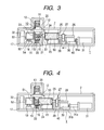
- FIG. 3 is a schematic cross sectional view of the inhaler before coupling an ejection head and a reservoir in the first embodiment.
- FIG. 4 is a schematic cross sectional view of the inhaler after coupling the ejection head and the reservoir in the first embodiment.
- FIG. 5 is a flowchart of a first inhaler control example.
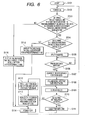
- FIG. 6 is a flowchart of a second inhaler control example.
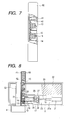
- FIG. 7 is an external view of an ejection head unit according to a second embodiment of the present invention.
- FIG. 8 is a schematic cross sectional view of an inhaler after coupling an ejection head and a reservoir in the second embodiment.
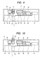
- FIG. 9 is a schematic cross sectional view of the inhaler before coupling the ejection head and the reservoir in the second embodiment.
- FIG. 10 is a schematic cross sectional view illustrating a state in which a spent ejection head is taken out with respect to the inhaler of the second embodiment.
- FIG. 1 is oblique perspective view in schematic form of an inhaler according to an embodiment of the present invention.
- the main unit outer casing is formed with a box-shaped housing case 1 that has an open surface and an access cover 2.
- the access cover 2 is attached in a freely turnable state through a hinge (not shown) to one side edge of the open surface of the housing case 1, and is urged at all times to open by an unshown spring.
- a hook claw (unshown) is provided on an end (unshown) of the access cover 2 that is opposite the hinge. The hook claw can be locked by engaging the hook claw with an engaging portion that is integrated with a lock release button 3 when closing the access cover 2, so that the access cover 2 does not open accidentally.
- the configuration is such that, when opening the access cover 2, the hook claw is released from the engaging portion by pushing the release button 3 so that the access cover 2 opens by the force of the spring.
- a display unit 5 for displaying the dosage, the time, and an error display is provided on the access cover 2.
- a menu button 6 and an up button 8, a down button 7, and a decision button 9 as setting buttons are provided to allow the user to carry out settings.
- the inhaler according to the present embodiment includes a revolver type ejection head unit.
- FIG. 2 is a schematic oblique perspective view of the revolver type ejection head unit.
- the ejection head unit 10 includes in a main body 11 a plurality of supporting portions 11a (four supporting portions are shown in the figure) that are disposed with intervals therebetween in the peripheral direction around a rotating shaft 12.
- the respective ejection heads 13 are detachably held and fixed.
- the ejection head unit is attachable to the inhaler.
- a plurality of ejection heads 13 are provided in the ejection head unit 10.
- Each ejection head 13 has a plurality of ejection nozzles for ejecting a medicine.
- An element that generates energy for ejecting the medicine is disposed in the vicinity of the ejection nozzles.
- a configuration having an electrothermal transducer that imparts thermal energy to a medicine a so-called thermal ink-jet system
- an electromechanical transducer that imparts mechanical energy to the medicine a so-called piezo ink-jet system
- a thermal ink-jet system can be used.
- the reproducibility and size precision with respect to the orifice diameter of the ejection nozzles, a thermal amount of a thermal pulse utilized for ejection, and a heater used therefor can be enhanced for each ejection head. Consequently, it is possible to achieve narrow droplet diameter distribution. Further, the production costs for the heads are low, and the applicability of the head to a small size apparatus for which it is necessary to frequently perform replacement is also high. Accordingly, in a case in which portability and convenience are required, such as the case of an inhaler, an ejection apparatus employing a thermal ink-jet system is particularly advantageous.
- FIG. 3 is a schematic cross sectional view of an inhaler according to the present embodiment.
- an opening 51 is provided in one portion of an air flow path 53 that is provided inside the housing case 1 and which guides medicine that the user inhale accompanying inspiration to a mouthpiece 4 ( FIG. 1 ) as a suction port.
- Droplets of medicine that are ejected from the ejection head 13 that is positioned at an ejection position facing the opening 51 are introduced into an air flow of the air flow path 53.
- medicine is guided together with the inhaled air in the direction of the mouthpiece 4.
- a pressure sensor 18 as an inhalation detection sensor is provided in a control board 17.
- a pressure detection nozzle 52 of the pressure sensor 18 communicates with the air flow path 53 through a hole 54. That is, the configuration enables a negative pressure that is generated inside the air flow path 53 by inhalation by the user to be detected by the pressure sensor 18.
- An inclination detection sensor (not shown) according to a 3-axis acceleration system is disposed in the control board 17.
- the inclination detection sensor is used to detect an abnormal inclination of the inhaler, and the detection result can be notified to the user by being displayed on the display unit 5 provided on the access cover 2 accompanied by a sound or a vibration generated by a vibrating motor or illumination by an LED.
- a RAM that stores prescription data or the like
- a ROM that stores an operation program for the inhaler
- a CPU that controls the inhaler based on the data stored in the ROM and RAM are provided on the control board 17.
- a contact pin 19 for passing a current of a charging-type battery 32 to the ejection head 13 is provided on the control board 17.
- the contact pin 19 comes in contact with an electric contact point 15 on an electric contact member 14 that is adhered to the outer periphery of the ejection head unit 10.
- a communicating tube 16 for allowing a reservoir 50 that stores a medicine and the ejection head 13 is provided in correspondence with each ejection head 13 in the ejection head unit 10. However, the ejection head 13 and the reservoir 50 do not communicate prior to use. This is to prevent the medicine from undergoing a change in quality by contact with air, and is done in consideration of the safety of the medicine.
- a flexible connecting membrane 24 is adherently disposed on the surface on the communicating tube 16 side of the reservoir 50, and prevents leakage of a medicine 23 from the reservoir 50.
- the revolver type ejection head unit 10 is rotated by taking the rotating shaft 12 as the rotation center and the rotation is stopped at a position at which the ejection nozzle of an unused ejection head 13 matched the opening 51 of the air flow path 53.
- a gear 20 is provided in an integrated condition with the rotating shaft 12 of the ejection head unit 10 so as to engage with a gear 21 that is mounted on a motor shaft of the ejection head driving motor 22.
- the ejection head unit 10 is rotated by a driving force of the ejection head driving motor 22, and a protrusion shape provided in the ejection head unit 10 is detected by a detection switch (a microswitch or a photosensor) to cause the ejection head unit 10 to stop at a position corresponding to the opening 51. More specifically, protrusions are provided in the ejection head unit 10 in the same amount as the amount of ejection heads 13, and are disposed so that their respective ejection heads 13 can be positioned at the opening 51 based on the relation with the detection switch. Positioning of the ejection head unit 10 may also be performed using an index plunger.
- adjustable means for causing the reservoir 50 to communicate with or separate from the ejection head 13 that is positioned at the opening is described.
- the shape of a communicating tube 16 for filling medicine into a sub-reservoir 33 of the ejection head 13 has a pointed tip.
- bar 31b stretches and the reservoir 50 moves together with a movable carriage 40 to the ejection head 13 side, and the communicating tube 16 penetrates the connecting membrane 24 provided on the reservoir 50 so that the ejection head 13 and the reservoir 50 communicate.
- the connecting membrane 24 may be a thick piece of rubber. In that case, by forming the communicating tube 16 using stainless steel and is a narrow shape like an injection needle, the communicating tube 16 can be inserted and extracted multiple times.
- FIG. 4 is a view illustrating a situation in which the solenoid 31 is operated to place the ejection head 13 and the reservoir 50 in a communicating state.
- a motor 30 for filling the medicine into the ejection head 13 rotates a screw gear 27 through a gear 28.
- a screw thread shape is formed on the inner diameter side of the screw gear 27, and a screw shaft 26 is provided that meshes with the screw thread shape.
- a rotation stopping shape for changing a rotational motion into a linear motion is formed in the screw shaft 26.
- a count area for the remaining number of unused ejection heads is provided in a storage portion (not shown: read and write enabled) inside the inhaler.
- the user sets the ejection head unit 10 that contains a plurality of the ejection heads 13 in the inhaler and also sets the reservoir 50 in the inhaler. Thereafter, when the user closes the access cover 2 of the inhaler, the inhaler executes initial settings such as displaying the message "Power On” on the display unit 5 (S001). Thereafter, at S002, the inhaler displays the message "Did you install an ejection head unit?" on the display unit 5, to request a decision from the user. If the user indicates "Yes” (presses the up setting button 8 of the inhaler), the inhaler switches to S017 to set the remaining number of unused ejection heads to four (initial value). Thereafter the inhaler switches to S003.
- the inhaler switches to S003.
- the ejection head unit 10 determines whether the counter for the remaining number of unused ejection heads 13 is one or more in order to determine there is an unused ejection head 13 mounted. If the result is "No”, the inhaler switches to S016 to display the message "Install a new ejection head unit” for a predetermined time, and then switches to S014. If the result at S003 is "Yes”, the inhaler switches to S004. At S004, the inhaler determines whether or not a reservoir is installed. If the result is "No", the inhaler switches to S015.
- the message "Install a reservoir” is displayed for a predetermined time, and the inhaler then switches to S014. If the result at S004 is "Yes", the inhaler switches to a dosage input mode at S005. At this time, the inhaler displays the initial value "01" for medicine ejection on the display unit 5. The patient can cause the desired dosage amount to be displayed by operating the up setting button 8 and the down setting button 7 of the inhaler. Thereafter, the inhaler switches to S006 at which the user presses the decision button 9 to confirm the set dosage. The inhaler next switches to S007.
- the inhaler drives the solenoid 31 so as to move the reservoir 50 a predetermined distance, and pierces the connecting membrane 24 with the communicating tube 16 that protrudes from the sub-reservoir 33 to connect the sub-reservoir 33 and the reservoir 50. Thereafter, at S008, the inhaler rotates the motor 30 a predetermined amount to push the plunger 25 with the screw shaft 26 via the gear 28 and the screw gear 27 to thereby fill medicine into the sub-reservoir 33 and the ejection head 13.
- the inhaler displays the message "Ready" (inhalation preparations complete) on the display unit 5, and at S010, waits for an inhalation action by the patient (detection of an inhalation action is performed by the pressure sensor 18). If the result of detection is "No” (negative pressure of an inhalation action is not detected), the inhaler continues to display “Ready” and to wait for an inhalation action. If the result of detection is "Yes” (negative pressure of an inhalation action is detected), the inhaler cancels the "Ready" display on the display unit 5 and proceeds to S011. At S011, the inhaler ejects a predetermined amount of medicine for a predetermined time. Thereafter, the inhaler switches to S012.
- the inhaler moves the ejection head unit by "the amount of one ejection head” (stops an unused ejection head at a position facing the opening 51).
- the inhaler switches to S013 to reduce the counter for the number of remaining ejection heads 13 by one.
- the inhaler then switches to S014, at which the inhaler cancels the "Power On” message that is displayed on the display unit 5 and switches to a "power off” mode. Thereafter, the inhaler waits to switch to S001 (Power On) when the access cover 2 of the inhaler is closed by the user.
- FIG. 6 is a flowchart that illustrates operations of a modification example that stores a counter value for the remaining number of unused ejection heads 13 inside the ejection head unit 10.
- a counter value "4" for the remaining number of unused ejection heads 13 is written in a storage portion (not shown: read and write enabled) inside the ejection head unit 10 at the time of factory shipment.
- the patient sets the ejection head unit 10 that contains a plurality of the ejection heads 13 in the inhaler and also sets the reservoir 50 in the inhaler. Thereafter, when the user closes the access cover 2 of the inhaler, the inhaler displays the message "Power On" on the display unit 5 (S102).
- the inhaler then electrically determines through the contact pin 19 that the ejection head unit 10 is installed and whether or not there are any unused ejection heads (S103). That is, the inhaler reads out the counter value for the remaining number of unused ejection heads 13 from the storage portion (not shown) of the ejection head unit 10 via the contact pin 19, and determines whether the counter for the remaining number of unused ejection heads 13 is one or more.
- the inhaler switches to S116 to display the message "Install a new ejection head unit" for a predetermined time, and then switches to S114. If the result at S103 is "Yes”, the inhaler switches to S104. At S104, the inhaler determines whether or not a reservoir is installed. If the result is “No”, the inhaler switches to S115. At S115, the inhaler displays the message “Install a reservoir” for a predetermined time, and then switches to S114. If the result at S104 is "Yes”, the inhaler switches to a dosage input mode at S105. At this time, the inhaler displays the initial value "01" for medicine ejection on the display unit 5.
- the patient can cause the desired dosage amount to be displayed by operating the up setting button 8 and the down setting button 7 of the inhaler. Thereafter, the inhaler switches to S106 at which the user presses the decision button 9 to confirm the set dosage. The inhaler then switches to S107. At S107, the inhaler drives the solenoid 31 so as to move the reservoir 50 a predetermined distance, and pierces the connecting membrane 24 with the communicating tube 16 that protrudes from the sub-reservoir 33 to connect the sub-reservoir 33 and the reservoir 50.
- the inhaler rotates the motor 30 a predetermined amount to push the plunger with the screw shaft 26 via the gear 28 and the screw gear 27 to thereby fill medicine into the sub-reservoir 33 and the ejection head 13.
- the inhaler displays the message "Ready" (inhalation preparations complete) on the display unit 5, and at S110, waits for an inhalation action by the patient (detection of an inhalation action is performed by the pressure sensor 18). If the result of detection is "No", the inhaler continues to display "Ready” and wait for an inhalation action. If the result of detection is "Yes”, the inhaler cancels the "Ready" display on the display unit 5 and proceeds to S111.
- the inhaler ejects a predetermined amount of medicine for a predetermined time. Thereafter, the inhaler switches to S112. At S112, the inhaler moves the ejection head 13 by "the amount of one ejection head" (stops an unused ejection head at a position facing the opening 51). Next, the inhaler switches to S113. At S113, the inhaler reads out the count value for the remaining number of unused ejection heads that is stored in the ejection head unit 10 through the contact pin 19, and writes in a new value in which the value that was read out is reduced by one. Thereafter, the inhaler switches to S114 to cancel the "Power On" message that is displayed on the display unit 5, switches to a "power off” mode, and returns to S102.
- FIG. 7 is a schematic external view of the ejection head unit according to the present embodiment.
- the ejection head unit of the present embodiment has a housing for accommodating a plurality of ejection heads within the ejection head unit.
- a plurality of ejection heads 13 is stored in a row inside a housing 60 in an overlapping state. By mounting the housing 60 in the inhaler, a plurality of ejection heads can be mounted with one operation.
- a compression spring 41 for moving the ejection head 13 inside the housing 60 is contained a compression spring 41 for moving the ejection head 13, and an ejection head 13 is pressurized at all times through a pressure plate 42 in the direction of the opposite face of the compression spring 41.
- an ejection head 13 at the end opposite the pressure plate is positioned at an ejection position facing the opening 51.
- the reservoir 50 that stores medicine corresponding to an inhalation amount for a plurality of times moves in a direction such that the connecting membrane 24 is pierced by the communicating tube 16 of the ejection head 13, to enter a communicating state with respect to the ejection head 13.
- the gear 28 rotates as a result of rotation of the motor 30, to thereby rotate the screw gear 27 that is engaged with the gear 28.
- the medicine filling screw shaft 26 that is disposed so as to mesh with the screw thread shape on the inner diameter side of the screw gear 27 pushes in the medicine filling plunger 25.
- filling of medicine in which medicine passes through the communicating tube 16 to the ejection head 13 is performed.
- a contact pin 19 for passing a current of a charging-type battery 32 to the ejection head 13 is provided on the control board 17.
- the contact pin 19 comes in contact with an electric contact point 15 on an electric contact member 14 that is adhered to the outer periphery of the ejection head 13.
- FIG. 9 is a cross sectional view that illustrates a state in which filling of medicine to the sub-reservoir 33 and the ejection head 13 is complete, the passage of current to the solenoid 31 is turned off, and the reservoir 50 has returned to a standby state.
- the inhaler waits for inhalation by the user.
- the inhaler commences ejection based on an inhalation detection signal.
- the pressure sensor 18 is provided on a sensor board 61 as an inhalation detection sensor.
- a hole 54 is provided in a part of the air flow path 53 that corresponds to the pressure detection nozzle 52 of the pressure sensor 18.
- FIG. 10 is a cross sectional view illustrating a state in which an ejection head 13 is taken out.
- the inhaler activates a solenoid 62 for discharging an ejection head to push out the used ejection head that is at an ejectable position to outside of the inhaler from an ejection head outlet 63 that is provided in the access cover 2.
- An outlet is also provided at one part of the housing 60 of the ejection head unit so as to match the position of the outlet 63.
- the compression spring 41 fulfills a function as a pushing mechanism that, when the ejection head is removed from the outlet 63, slides to a position at which ejection is enabled a single ejection head that was adjacent within the housing to the ejection head that is removed, and a function as positioning means for positioning a single ejection head among the plurality of ejection heads at the opening 51.
- medicine is filled again into the unused ejection head and inhalation performed.
- the housing 60 When there are no more unused ejection heads, the housing 60 is replaced.
- the operation flowchart is the same as in the first embodiment, and is thus omitted here.
- the ejection head unit includes the housing 60.
- the configuration may be one in which a plurality of ejection heads are unitized and stored in one row inside the inhaler.
- the inhaler of the present invention is not limited to use for inhaling medicine and can be used for various uses that require certain and hygienic droplet ejection.
- the inhaler of the present invention can also be used for a mist ejection apparatus for ejecting an aromatic substance or for an inhaler of a substance of liking of a user such as nicotine.
- An ejection head unit being attachable to an inhaler for ejecting a medicine to cause a user to inhale the medicine has a plurality of ejection heads having an element generating energy for ejecting the medicine, and a plurality of ejection nozzles through which the medicine is ejected by the element.
- An inhaler for ejecting a medicine to allow inhalation thereof by a user has an air flow path guiding a medicine that is inhaled accompanying inspiration by the user to a suction port, an ejection head unit having a plurality of ejection heads including an element generating energy for ejecting the medicine and a plurality of ejection nozzles through which the medicine is ejected by the element, and a positioning unit for positioning a single ejection head among the plurality of ejection heads at an opening provided in one portion of the air flow path.
Landscapes
- Health & Medical Sciences (AREA)
- Engineering & Computer Science (AREA)
- Life Sciences & Earth Sciences (AREA)
- Animal Behavior & Ethology (AREA)
- General Health & Medical Sciences (AREA)
- Public Health (AREA)
- Veterinary Medicine (AREA)
- Bioinformatics & Cheminformatics (AREA)
- Pulmonology (AREA)
- Anesthesiology (AREA)
- Biomedical Technology (AREA)
- Heart & Thoracic Surgery (AREA)
- Hematology (AREA)
- Epidemiology (AREA)
- Medicinal Preparation (AREA)
- Particle Formation And Scattering Control In Inkjet Printers (AREA)
- Special Spraying Apparatus (AREA)
Applications Claiming Priority (2)
| Application Number | Priority Date | Filing Date | Title |
|---|---|---|---|
| JP2007067973 | 2007-03-16 | ||
| JP2008014431A JP5247165B2 (ja) | 2007-03-16 | 2008-01-25 | 吐出ヘッドユニット |
Publications (3)
| Publication Number | Publication Date |
|---|---|
| EP1970087A2 true EP1970087A2 (de) | 2008-09-17 |
| EP1970087A3 EP1970087A3 (de) | 2009-03-11 |
| EP1970087B1 EP1970087B1 (de) | 2011-05-18 |
Family
ID=39473900
Family Applications (1)
| Application Number | Title | Priority Date | Filing Date |
|---|---|---|---|
| EP08152317A Not-in-force EP1970087B1 (de) | 2007-03-16 | 2008-03-05 | Inhalierer und Ausgabekopfeinheit, die an dem Inhalierer befestigt werden kann |
Country Status (4)
| Country | Link |
|---|---|
| US (1) | US8616199B2 (de) |
| EP (1) | EP1970087B1 (de) |
| AU (1) | AU2008201084A1 (de) |
| CA (1) | CA2623920C (de) |
Cited By (3)
| Publication number | Priority date | Publication date | Assignee | Title |
|---|---|---|---|---|
| US9035765B2 (en) | 2013-08-28 | 2015-05-19 | Gecko Health Innovations, Inc. | Devices, systems, and methods for adherence monitoring and devices, systems, and methods for monitoring use of consumable dispensers |
| US10155094B2 (en) | 2010-06-18 | 2018-12-18 | Boehringer Ingelheim International Gmbh | Inhaler |
| US11253661B2 (en) | 2012-06-25 | 2022-02-22 | Gecko Health Innovations, Inc. | Devices, systems, and methods for adherence monitoring and patient interaction |
Families Citing this family (7)
| Publication number | Priority date | Publication date | Assignee | Title |
|---|---|---|---|---|
| EP1866016A4 (de) * | 2005-03-30 | 2011-02-16 | Canon Kk | Vorrichtung zum ausstossen flüssiger arzneimittel |
| US20090095292A1 (en) * | 2006-04-10 | 2009-04-16 | Canon Kabushiki Kaisha | Ingesta administration device |
| JP2009050285A (ja) * | 2007-08-23 | 2009-03-12 | Canon Inc | 吸入装置 |
| JP5264230B2 (ja) * | 2008-03-18 | 2013-08-14 | キヤノン株式会社 | 薬剤吐出装置及びその制御方法 |
| US9521963B2 (en) * | 2008-05-13 | 2016-12-20 | Ric Investments, Llc | Respiratory component measurement system with indicating elements |
| US8495998B2 (en) | 2009-06-17 | 2013-07-30 | British American Tobacco (Investments) Limited | Inhaler |
| HK1252464B (en) * | 2015-07-20 | 2020-05-22 | Pearl Therapeutics, Inc. | Aerosol delivery systems |
Citations (2)
| Publication number | Priority date | Publication date | Assignee | Title |
|---|---|---|---|---|
| WO1995001137A1 (en) | 1993-06-29 | 1995-01-12 | Voges Innovation Pty. Ltd. | Dispenser |
| WO2002004043A2 (en) | 2000-07-12 | 2002-01-17 | Vapotronics Inc. | Inhaler with removable droplet ejection cartridge |
Family Cites Families (16)
| Publication number | Priority date | Publication date | Assignee | Title |
|---|---|---|---|---|
| GB9004781D0 (en) | 1990-03-02 | 1990-04-25 | Glaxo Group Ltd | Device |
| US5888477A (en) * | 1993-01-29 | 1999-03-30 | Aradigm Corporation | Use of monomeric insulin as a means for improving the bioavailability of inhaled insulin |
| US5970974A (en) * | 1995-03-14 | 1999-10-26 | Siemens Aktiengesellschaft | Dosating unit for an ultrasonic atomizer device |
| DK0923957T3 (da) * | 1997-11-19 | 2002-02-18 | Microflow Eng Sa | Dyseemne og væskedråbesprøjteindretning til en inhalator egnet til respirationsterapi |
| US6810872B1 (en) | 1999-12-10 | 2004-11-02 | Unisia Jecs Corporation | Inhalant medicator |
| GB0025749D0 (en) * | 2000-10-20 | 2000-12-06 | Glaxo Group Ltd | Inhaler |
| US7073499B1 (en) | 2001-02-06 | 2006-07-11 | Injet Digital Aerosols Limited | Inhaler with airflow regulation |
| US20020134373A1 (en) * | 2001-03-20 | 2002-09-26 | Igor Gonda | Aerosol generation using sterile multiple dose containers |
| US6684880B2 (en) * | 2001-12-04 | 2004-02-03 | Hewlett-Packard Development Company, L.P. | Applicator for dispensing bioactive compositions and methods for using the same |
| US7467630B2 (en) * | 2004-02-11 | 2008-12-23 | Hewlett-Packard Development Company, L.P. | Medicament dispenser |
| RU2362593C2 (ru) | 2004-08-02 | 2009-07-27 | Кэнон Кабусики Кайся | Ингаляционное устройство (варианты) |
| US20060081239A1 (en) * | 2004-10-15 | 2006-04-20 | Alley Rodney L | Thermally efficient drop generator |
| JP4789555B2 (ja) | 2005-09-13 | 2011-10-12 | キヤノン株式会社 | 液剤吐出装置 |
| US7779835B2 (en) | 2006-04-17 | 2010-08-24 | Canon Kabushiki Kaisha | Liquid ejection device |
| JP4898566B2 (ja) | 2006-07-13 | 2012-03-14 | キヤノン株式会社 | 薬剤吐出制御方法および薬剤吐出装置 |
| JP4895388B2 (ja) | 2006-07-25 | 2012-03-14 | キヤノン株式会社 | 薬剤吐出装置 |
-
2008
- 2008-02-25 US US12/036,610 patent/US8616199B2/en not_active Expired - Fee Related
- 2008-03-04 CA CA2623920A patent/CA2623920C/en not_active Expired - Fee Related
- 2008-03-05 EP EP08152317A patent/EP1970087B1/de not_active Not-in-force
- 2008-03-06 AU AU2008201084A patent/AU2008201084A1/en not_active Abandoned
Patent Citations (2)
| Publication number | Priority date | Publication date | Assignee | Title |
|---|---|---|---|---|
| WO1995001137A1 (en) | 1993-06-29 | 1995-01-12 | Voges Innovation Pty. Ltd. | Dispenser |
| WO2002004043A2 (en) | 2000-07-12 | 2002-01-17 | Vapotronics Inc. | Inhaler with removable droplet ejection cartridge |
Cited By (7)
| Publication number | Priority date | Publication date | Assignee | Title |
|---|---|---|---|---|
| US10155094B2 (en) | 2010-06-18 | 2018-12-18 | Boehringer Ingelheim International Gmbh | Inhaler |
| US11253661B2 (en) | 2012-06-25 | 2022-02-22 | Gecko Health Innovations, Inc. | Devices, systems, and methods for adherence monitoring and patient interaction |
| US11938265B2 (en) | 2012-06-25 | 2024-03-26 | Gecko Health Innovations, Inc. | Devices, systems, and methods for adherence monitoring and patient interaction |
| US9035765B2 (en) | 2013-08-28 | 2015-05-19 | Gecko Health Innovations, Inc. | Devices, systems, and methods for adherence monitoring and devices, systems, and methods for monitoring use of consumable dispensers |
| US9728068B2 (en) | 2013-08-28 | 2017-08-08 | Gecko Health Innovations, Inc. | Devices, systems, and methods for adherence monitoring and devices, systems, and methods for monitoring use of consumable dispensers |
| US10002517B2 (en) | 2013-08-28 | 2018-06-19 | Gecko Health Innovations, Inc. | Devices, systems, and methods for adherence monitoring and devices, systems, and methods for monitoring use of consumable dispensers |
| US10573161B2 (en) | 2013-08-28 | 2020-02-25 | Gecko Health Innovations, Inc. | Devices, systems, and methods for adherence monitoring and devices, systems, and methods for monitoring use of consumable dispensers |
Also Published As
| Publication number | Publication date |
|---|---|
| EP1970087B1 (de) | 2011-05-18 |
| AU2008201084A1 (en) | 2008-10-02 |
| US8616199B2 (en) | 2013-12-31 |
| CA2623920A1 (en) | 2008-09-16 |
| US20080223362A1 (en) | 2008-09-18 |
| CA2623920C (en) | 2011-05-24 |
| EP1970087A3 (de) | 2009-03-11 |
Similar Documents
| Publication | Publication Date | Title |
|---|---|---|
| CA2623920C (en) | Inhaler and ejection head unit attachable to the inhaler | |
| EP3108966B1 (de) | Inhalator | |
| JP4789555B2 (ja) | 液剤吐出装置 | |
| JP5207679B2 (ja) | 薬剤吐出装置 | |
| US20070227534A1 (en) | Inhaling Apparatus | |
| EP3311868B1 (de) | Inhalatorvorrichtung und -verfahren | |
| JP4789567B2 (ja) | 液体吐出装置 | |
| TWI253428B (en) | Medicament dispenser | |
| EP1847287A1 (de) | Flüssigkeitsausstoßvorrichtung | |
| JP2009195669A (ja) | 薬剤吐出装置及びその制御方法 | |
| JP2007296384A (ja) | 薬剤吐出装置 | |
| EP2143457A1 (de) | Inhalator | |
| JP5247165B2 (ja) | 吐出ヘッドユニット | |
| JP4695940B2 (ja) | 吸入装置 | |
| JP4920935B2 (ja) | 液剤吐出装置 | |
| JP2004350985A (ja) | 肺吸引用液滴吐出装置 | |
| JP2009219778A (ja) | 薬剤吐出装置及びその制御方法 | |
| JP2004350976A (ja) | 肺吸引用液滴吐出装置 |
Legal Events
| Date | Code | Title | Description |
|---|---|---|---|
| PUAI | Public reference made under article 153(3) epc to a published international application that has entered the european phase |
Free format text: ORIGINAL CODE: 0009012 |
|
| AK | Designated contracting states |
Kind code of ref document: A2 Designated state(s): AT BE BG CH CY CZ DE DK EE ES FI FR GB GR HR HU IE IS IT LI LT LU LV MC MT NL NO PL PT RO SE SI SK TR |
|
| AX | Request for extension of the european patent |
Extension state: AL BA MK RS |
|
| PUAL | Search report despatched |
Free format text: ORIGINAL CODE: 0009013 |
|
| AK | Designated contracting states |
Kind code of ref document: A3 Designated state(s): AT BE BG CH CY CZ DE DK EE ES FI FR GB GR HR HU IE IS IT LI LT LU LV MC MT NL NO PL PT RO SE SI SK TR |
|
| AX | Request for extension of the european patent |
Extension state: AL BA MK RS |
|
| 17P | Request for examination filed |
Effective date: 20090911 |
|
| AKX | Designation fees paid |
Designated state(s): AT BE BG CH CY CZ DE DK EE ES FI FR GB GR HR HU IE IS IT LI LT LU LV MC MT NL NO PL PT RO SE SI SK TR |
|
| 17Q | First examination report despatched |
Effective date: 20091222 |
|
| GRAP | Despatch of communication of intention to grant a patent |
Free format text: ORIGINAL CODE: EPIDOSNIGR1 |
|
| GRAS | Grant fee paid |
Free format text: ORIGINAL CODE: EPIDOSNIGR3 |
|
| GRAA | (expected) grant |
Free format text: ORIGINAL CODE: 0009210 |
|
| REG | Reference to a national code |
Ref country code: GB Ref legal event code: FG4D |
|
| REG | Reference to a national code |
Ref country code: CH Ref legal event code: EP |
|
| REG | Reference to a national code |
Ref country code: IE Ref legal event code: FG4D |
|
| REG | Reference to a national code |
Ref country code: DE Ref legal event code: R096 Ref document number: 602008006955 Country of ref document: DE Effective date: 20110630 |
|
| REG | Reference to a national code |
Ref country code: NL Ref legal event code: VDEP Effective date: 20110518 |
|
| PG25 | Lapsed in a contracting state [announced via postgrant information from national office to epo] |
Ref country code: HR Free format text: LAPSE BECAUSE OF FAILURE TO SUBMIT A TRANSLATION OF THE DESCRIPTION OR TO PAY THE FEE WITHIN THE PRESCRIBED TIME-LIMIT Effective date: 20110518 Ref country code: LT Free format text: LAPSE BECAUSE OF FAILURE TO SUBMIT A TRANSLATION OF THE DESCRIPTION OR TO PAY THE FEE WITHIN THE PRESCRIBED TIME-LIMIT Effective date: 20110518 Ref country code: PT Free format text: LAPSE BECAUSE OF FAILURE TO SUBMIT A TRANSLATION OF THE DESCRIPTION OR TO PAY THE FEE WITHIN THE PRESCRIBED TIME-LIMIT Effective date: 20110919 Ref country code: SE Free format text: LAPSE BECAUSE OF FAILURE TO SUBMIT A TRANSLATION OF THE DESCRIPTION OR TO PAY THE FEE WITHIN THE PRESCRIBED TIME-LIMIT Effective date: 20110518 Ref country code: NO Free format text: LAPSE BECAUSE OF FAILURE TO SUBMIT A TRANSLATION OF THE DESCRIPTION OR TO PAY THE FEE WITHIN THE PRESCRIBED TIME-LIMIT Effective date: 20110818 |
|
| PG25 | Lapsed in a contracting state [announced via postgrant information from national office to epo] |
Ref country code: GR Free format text: LAPSE BECAUSE OF FAILURE TO SUBMIT A TRANSLATION OF THE DESCRIPTION OR TO PAY THE FEE WITHIN THE PRESCRIBED TIME-LIMIT Effective date: 20110819 Ref country code: BE Free format text: LAPSE BECAUSE OF FAILURE TO SUBMIT A TRANSLATION OF THE DESCRIPTION OR TO PAY THE FEE WITHIN THE PRESCRIBED TIME-LIMIT Effective date: 20110518 Ref country code: FI Free format text: LAPSE BECAUSE OF FAILURE TO SUBMIT A TRANSLATION OF THE DESCRIPTION OR TO PAY THE FEE WITHIN THE PRESCRIBED TIME-LIMIT Effective date: 20110518 Ref country code: ES Free format text: LAPSE BECAUSE OF FAILURE TO SUBMIT A TRANSLATION OF THE DESCRIPTION OR TO PAY THE FEE WITHIN THE PRESCRIBED TIME-LIMIT Effective date: 20110829 Ref country code: SI Free format text: LAPSE BECAUSE OF FAILURE TO SUBMIT A TRANSLATION OF THE DESCRIPTION OR TO PAY THE FEE WITHIN THE PRESCRIBED TIME-LIMIT Effective date: 20110518 Ref country code: AT Free format text: LAPSE BECAUSE OF FAILURE TO SUBMIT A TRANSLATION OF THE DESCRIPTION OR TO PAY THE FEE WITHIN THE PRESCRIBED TIME-LIMIT Effective date: 20110518 Ref country code: LV Free format text: LAPSE BECAUSE OF FAILURE TO SUBMIT A TRANSLATION OF THE DESCRIPTION OR TO PAY THE FEE WITHIN THE PRESCRIBED TIME-LIMIT Effective date: 20110518 Ref country code: IS Free format text: LAPSE BECAUSE OF FAILURE TO SUBMIT A TRANSLATION OF THE DESCRIPTION OR TO PAY THE FEE WITHIN THE PRESCRIBED TIME-LIMIT Effective date: 20110918 Ref country code: CY Free format text: LAPSE BECAUSE OF FAILURE TO SUBMIT A TRANSLATION OF THE DESCRIPTION OR TO PAY THE FEE WITHIN THE PRESCRIBED TIME-LIMIT Effective date: 20110518 |
|
| PG25 | Lapsed in a contracting state [announced via postgrant information from national office to epo] |
Ref country code: NL Free format text: LAPSE BECAUSE OF FAILURE TO SUBMIT A TRANSLATION OF THE DESCRIPTION OR TO PAY THE FEE WITHIN THE PRESCRIBED TIME-LIMIT Effective date: 20110518 |
|
| PG25 | Lapsed in a contracting state [announced via postgrant information from national office to epo] |
Ref country code: CZ Free format text: LAPSE BECAUSE OF FAILURE TO SUBMIT A TRANSLATION OF THE DESCRIPTION OR TO PAY THE FEE WITHIN THE PRESCRIBED TIME-LIMIT Effective date: 20110518 Ref country code: EE Free format text: LAPSE BECAUSE OF FAILURE TO SUBMIT A TRANSLATION OF THE DESCRIPTION OR TO PAY THE FEE WITHIN THE PRESCRIBED TIME-LIMIT Effective date: 20110518 |
|
| PG25 | Lapsed in a contracting state [announced via postgrant information from national office to epo] |
Ref country code: SK Free format text: LAPSE BECAUSE OF FAILURE TO SUBMIT A TRANSLATION OF THE DESCRIPTION OR TO PAY THE FEE WITHIN THE PRESCRIBED TIME-LIMIT Effective date: 20110518 Ref country code: DK Free format text: LAPSE BECAUSE OF FAILURE TO SUBMIT A TRANSLATION OF THE DESCRIPTION OR TO PAY THE FEE WITHIN THE PRESCRIBED TIME-LIMIT Effective date: 20110518 Ref country code: PL Free format text: LAPSE BECAUSE OF FAILURE TO SUBMIT A TRANSLATION OF THE DESCRIPTION OR TO PAY THE FEE WITHIN THE PRESCRIBED TIME-LIMIT Effective date: 20110518 Ref country code: RO Free format text: LAPSE BECAUSE OF FAILURE TO SUBMIT A TRANSLATION OF THE DESCRIPTION OR TO PAY THE FEE WITHIN THE PRESCRIBED TIME-LIMIT Effective date: 20110518 |
|
| PLBE | No opposition filed within time limit |
Free format text: ORIGINAL CODE: 0009261 |
|
| STAA | Information on the status of an ep patent application or granted ep patent |
Free format text: STATUS: NO OPPOSITION FILED WITHIN TIME LIMIT |
|
| 26N | No opposition filed |
Effective date: 20120221 |
|
| PG25 | Lapsed in a contracting state [announced via postgrant information from national office to epo] |
Ref country code: IT Free format text: LAPSE BECAUSE OF FAILURE TO SUBMIT A TRANSLATION OF THE DESCRIPTION OR TO PAY THE FEE WITHIN THE PRESCRIBED TIME-LIMIT Effective date: 20110518 |
|
| REG | Reference to a national code |
Ref country code: DE Ref legal event code: R097 Ref document number: 602008006955 Country of ref document: DE Effective date: 20120221 |
|
| PG25 | Lapsed in a contracting state [announced via postgrant information from national office to epo] |
Ref country code: MC Free format text: LAPSE BECAUSE OF NON-PAYMENT OF DUE FEES Effective date: 20120331 |
|
| REG | Reference to a national code |
Ref country code: CH Ref legal event code: PL |
|
| REG | Reference to a national code |
Ref country code: FR Ref legal event code: ST Effective date: 20121130 |
|
| REG | Reference to a national code |
Ref country code: IE Ref legal event code: MM4A |
|
| PG25 | Lapsed in a contracting state [announced via postgrant information from national office to epo] |
Ref country code: FR Free format text: LAPSE BECAUSE OF NON-PAYMENT OF DUE FEES Effective date: 20120402 Ref country code: LI Free format text: LAPSE BECAUSE OF NON-PAYMENT OF DUE FEES Effective date: 20120331 Ref country code: CH Free format text: LAPSE BECAUSE OF NON-PAYMENT OF DUE FEES Effective date: 20120331 Ref country code: IE Free format text: LAPSE BECAUSE OF NON-PAYMENT OF DUE FEES Effective date: 20120305 |
|
| PG25 | Lapsed in a contracting state [announced via postgrant information from national office to epo] |
Ref country code: BG Free format text: LAPSE BECAUSE OF FAILURE TO SUBMIT A TRANSLATION OF THE DESCRIPTION OR TO PAY THE FEE WITHIN THE PRESCRIBED TIME-LIMIT Effective date: 20110818 |
|
| PG25 | Lapsed in a contracting state [announced via postgrant information from national office to epo] |
Ref country code: MT Free format text: LAPSE BECAUSE OF FAILURE TO SUBMIT A TRANSLATION OF THE DESCRIPTION OR TO PAY THE FEE WITHIN THE PRESCRIBED TIME-LIMIT Effective date: 20110518 |
|
| PG25 | Lapsed in a contracting state [announced via postgrant information from national office to epo] |
Ref country code: TR Free format text: LAPSE BECAUSE OF FAILURE TO SUBMIT A TRANSLATION OF THE DESCRIPTION OR TO PAY THE FEE WITHIN THE PRESCRIBED TIME-LIMIT Effective date: 20110518 |
|
| PG25 | Lapsed in a contracting state [announced via postgrant information from national office to epo] |
Ref country code: LU Free format text: LAPSE BECAUSE OF NON-PAYMENT OF DUE FEES Effective date: 20120305 |
|
| PG25 | Lapsed in a contracting state [announced via postgrant information from national office to epo] |
Ref country code: HU Free format text: LAPSE BECAUSE OF FAILURE TO SUBMIT A TRANSLATION OF THE DESCRIPTION OR TO PAY THE FEE WITHIN THE PRESCRIBED TIME-LIMIT Effective date: 20080305 |
|
| PGFP | Annual fee paid to national office [announced via postgrant information from national office to epo] |
Ref country code: GB Payment date: 20150316 Year of fee payment: 8 |
|
| PGFP | Annual fee paid to national office [announced via postgrant information from national office to epo] |
Ref country code: DE Payment date: 20150331 Year of fee payment: 8 |
|
| REG | Reference to a national code |
Ref country code: DE Ref legal event code: R119 Ref document number: 602008006955 Country of ref document: DE |
|
| GBPC | Gb: european patent ceased through non-payment of renewal fee |
Effective date: 20160305 |
|
| PG25 | Lapsed in a contracting state [announced via postgrant information from national office to epo] |
Ref country code: GB Free format text: LAPSE BECAUSE OF NON-PAYMENT OF DUE FEES Effective date: 20160305 Ref country code: DE Free format text: LAPSE BECAUSE OF NON-PAYMENT OF DUE FEES Effective date: 20161001 |