EP1969264B1 - Abnehmbares sitzventilelement für ein membranenventil - Google Patents
Abnehmbares sitzventilelement für ein membranenventil Download PDFInfo
- Publication number
- EP1969264B1 EP1969264B1 EP06850303A EP06850303A EP1969264B1 EP 1969264 B1 EP1969264 B1 EP 1969264B1 EP 06850303 A EP06850303 A EP 06850303A EP 06850303 A EP06850303 A EP 06850303A EP 1969264 B1 EP1969264 B1 EP 1969264B1
- Authority
- EP
- European Patent Office
- Prior art keywords
- seat member
- valve
- channel
- sleeve
- bore
- Prior art date
- Legal status (The legal status is an assumption and is not a legal conclusion. Google has not performed a legal analysis and makes no representation as to the accuracy of the status listed.)
- Not-in-force
Links
- 239000012530 fluid Substances 0.000 claims abstract description 24
- 238000000034 method Methods 0.000 claims abstract description 8
- 238000004891 communication Methods 0.000 claims abstract description 4
- 239000000463 material Substances 0.000 claims description 13
- 238000009434 installation Methods 0.000 claims description 6
- 230000008602 contraction Effects 0.000 claims description 5
- 230000008901 benefit Effects 0.000 description 7
- 238000010276 construction Methods 0.000 description 5
- 230000006835 compression Effects 0.000 description 3
- 238000007906 compression Methods 0.000 description 3
- 229910052755 nonmetal Inorganic materials 0.000 description 3
- 239000002184 metal Substances 0.000 description 2
- 230000002265 prevention Effects 0.000 description 2
- 230000004044 response Effects 0.000 description 2
- 239000004696 Poly ether ether ketone Substances 0.000 description 1
- 239000003518 caustics Substances 0.000 description 1
- 230000000694 effects Effects 0.000 description 1
- 238000003780 insertion Methods 0.000 description 1
- 230000037431 insertion Effects 0.000 description 1
- 239000007788 liquid Substances 0.000 description 1
- 238000012986 modification Methods 0.000 description 1
- 230000004048 modification Effects 0.000 description 1
- 230000035515 penetration Effects 0.000 description 1
- 230000035699 permeability Effects 0.000 description 1
- 239000004033 plastic Substances 0.000 description 1
- 229920002493 poly(chlorotrifluoroethylene) Polymers 0.000 description 1
- -1 polychlorotrifluoroethylene Polymers 0.000 description 1
- 239000005023 polychlorotrifluoroethylene (PCTFE) polymer Substances 0.000 description 1
- 229920002530 polyetherether ketone Polymers 0.000 description 1
- 230000008569 process Effects 0.000 description 1
- 230000002035 prolonged effect Effects 0.000 description 1
- 230000000630 rising effect Effects 0.000 description 1
- 238000010079 rubber tapping Methods 0.000 description 1
- 238000007789 sealing Methods 0.000 description 1
- 235000008790 seltzer Nutrition 0.000 description 1
- 238000004513 sizing Methods 0.000 description 1
- 230000008961 swelling Effects 0.000 description 1
- 229920003002 synthetic resin Polymers 0.000 description 1
- 239000000057 synthetic resin Substances 0.000 description 1
- 238000005382 thermal cycling Methods 0.000 description 1
Images


Classifications
-
- F—MECHANICAL ENGINEERING; LIGHTING; HEATING; WEAPONS; BLASTING
- F16—ENGINEERING ELEMENTS AND UNITS; GENERAL MEASURES FOR PRODUCING AND MAINTAINING EFFECTIVE FUNCTIONING OF MACHINES OR INSTALLATIONS; THERMAL INSULATION IN GENERAL
- F16K—VALVES; TAPS; COCKS; ACTUATING-FLOATS; DEVICES FOR VENTING OR AERATING
- F16K1/00—Lift valves or globe valves, i.e. cut-off apparatus with closure members having at least a component of their opening and closing motion perpendicular to the closing faces
- F16K1/32—Details
- F16K1/34—Cutting-off parts, e.g. valve members, seats
- F16K1/42—Valve seats
- F16K1/425—Attachment of the seat to the housing by plastical deformation, e.g. valve seat or housing being plastically deformed during mounting
-
- F—MECHANICAL ENGINEERING; LIGHTING; HEATING; WEAPONS; BLASTING
- F16—ENGINEERING ELEMENTS AND UNITS; GENERAL MEASURES FOR PRODUCING AND MAINTAINING EFFECTIVE FUNCTIONING OF MACHINES OR INSTALLATIONS; THERMAL INSULATION IN GENERAL
- F16K—VALVES; TAPS; COCKS; ACTUATING-FLOATS; DEVICES FOR VENTING OR AERATING
- F16K1/00—Lift valves or globe valves, i.e. cut-off apparatus with closure members having at least a component of their opening and closing motion perpendicular to the closing faces
- F16K1/32—Details
- F16K1/34—Cutting-off parts, e.g. valve members, seats
- F16K1/42—Valve seats
-
- F—MECHANICAL ENGINEERING; LIGHTING; HEATING; WEAPONS; BLASTING
- F16—ENGINEERING ELEMENTS AND UNITS; GENERAL MEASURES FOR PRODUCING AND MAINTAINING EFFECTIVE FUNCTIONING OF MACHINES OR INSTALLATIONS; THERMAL INSULATION IN GENERAL
- F16K—VALVES; TAPS; COCKS; ACTUATING-FLOATS; DEVICES FOR VENTING OR AERATING
- F16K7/00—Diaphragm valves or cut-off apparatus, e.g. with a member deformed, but not moved bodily, to close the passage ; Pinch valves
- F16K7/12—Diaphragm valves or cut-off apparatus, e.g. with a member deformed, but not moved bodily, to close the passage ; Pinch valves with flat, dished, or bowl-shaped diaphragm
- F16K7/14—Diaphragm valves or cut-off apparatus, e.g. with a member deformed, but not moved bodily, to close the passage ; Pinch valves with flat, dished, or bowl-shaped diaphragm arranged to be deformed against a flat seat
-
- F—MECHANICAL ENGINEERING; LIGHTING; HEATING; WEAPONS; BLASTING
- F16—ENGINEERING ELEMENTS AND UNITS; GENERAL MEASURES FOR PRODUCING AND MAINTAINING EFFECTIVE FUNCTIONING OF MACHINES OR INSTALLATIONS; THERMAL INSULATION IN GENERAL
- F16K—VALVES; TAPS; COCKS; ACTUATING-FLOATS; DEVICES FOR VENTING OR AERATING
- F16K7/00—Diaphragm valves or cut-off apparatus, e.g. with a member deformed, but not moved bodily, to close the passage ; Pinch valves
- F16K7/12—Diaphragm valves or cut-off apparatus, e.g. with a member deformed, but not moved bodily, to close the passage ; Pinch valves with flat, dished, or bowl-shaped diaphragm
- F16K7/14—Diaphragm valves or cut-off apparatus, e.g. with a member deformed, but not moved bodily, to close the passage ; Pinch valves with flat, dished, or bowl-shaped diaphragm arranged to be deformed against a flat seat
- F16K7/16—Diaphragm valves or cut-off apparatus, e.g. with a member deformed, but not moved bodily, to close the passage ; Pinch valves with flat, dished, or bowl-shaped diaphragm arranged to be deformed against a flat seat the diaphragm being mechanically actuated, e.g. by screw-spindle or cam
Definitions
- the present invention is directed to a valve construction, and more particularly, the present invention is directed to a valve seat construction for diaphragm valves.
- Valves are widely used to provide precision flow and/or pressure control of fluids. Diaphragm valves are preferred in many applications due to the valve member being directed into and out of contact with a diaphragm, which likewise directs a valve seat into and out of engagement with the diaphragm to effect the desired fluid flow/pressure control. Other attributes diaphragm valves have are low internal volume, high sealing integrity, compact size and fast actuation/operation.
- valve components After being subjected to operational use, especially involving caustic or abrasive fluids and/or particulates or condensates, valve components, notably the valve seats, become worn or damaged so that the valve can no longer function properly.
- One solution is to replace the entire valve, which requires disconnecting the old valve from the connections of the using application or system, and then re-establishing those system connections. In addition to the cost of the replacement valve, care must be taken to ensure the system connections to the replacement valve do not leak.
- U.S. Patent No. 4,715,578 to Seltzer discloses a valve seat member composed of a synthetic resin that is threadedly engaged with the valve body, including an O-ring disposed between the valve seat member and the valve body.
- the valve seat member is susceptible to working loose from the valve body.
- U.S. Patent No. 6,854,713 to Lin et al. discloses a valve body having a cylindrical opening formed in a flow channel for receiving a cylindrical non-metal valve base.
- the opening includes a groove formed in the valve body.
- 6,854,713 is not directed to a replaceable valve base. Moreover, the process of press-fitting the tightly fitting ring inside the valve base will necessarily deform the surface of the valve base contacting the diaphragm, which will compromise the quality of the seal between the valve base and the diaphragm. Finally, due to a portion of the valve base flowing into the groove in the opening securing the valve base within the valve body as it is deformed, it is unlikely that the valve base can be removed without damaging the valve body, which would necessitate replacement of the entire valve.
- the present invention relates to a diaphragm valve in accordance with claim 1.
- the present invention still further relates to a method of constructing a diaphragm valve according to claim 12.
- An advantage of the present invention is that it allows for replacement of a valve seat for a diaphragm valve without replacing the valve.
- Another advantage of the present invention is that it prevents creep of a valve seat for a diaphragm valve.
- a further advantage of the present invention is that it applies a constant compressive force to retain a valve seat in position in the valve body.
- Figure 1 is a partial exploded perspective view of an unassembled valve of the present invention.
- Figure 2 is a partial exploded cross section of an unassembled valve taken along line 1-1 of the present invention.
- Figure 3 is a cross section of an assembled valve seat member of the present invention.
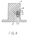
- Figure 4 is cross section of an assembled valve of the present invention.
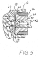
- Figure 5 is an enlarged partial cross section of an assembled valve of the present invention.
- valve 10 includes a valve body 12 having a valve cavity 18 further opening into separate channels 20, 24 for directing a fluid through the valve body 12.
- a counterbored penetration or bore 22 receives a sleeve 16 and a seat member 14 that are preassembled prior to insertion into the bore 22.
- a diaphragm 28 is installed over the seat member 14, and a collet 34 is then installed in the valve cavity 18 over the diaphragm 28.
- a lower portion 26 of the valve cavity 18, including an annular ridge 30 extending outwardly from the valve cavity 18 and the diaphragm 28 define an enclosed region 32 for permitting the selective flow of fluid between the channels 20, 24.
- a nut 36 having a tapered shoulder 62 is threadedly engaged to abut a corresponding tapered surface of the collet 34 in the valve cavity 18.
- a valve member 38 is slidably disposed in an aperture 40 formed in the collet 34 for abutting the diaphragm 28.
- a stem 42 applies an axial force, such as by a pressurized fluid directed through a passageway 44 formed in the stem 42.
- other means such as springs (not shown) can also provide the axial forces.
- valve member 38 Upon application of sufficient axial forces by or through stem 42, valve member 38 is urged into contact with diaphragm 28 so that diaphragm 28 abuts seat member 14 to interrupt fluid communication between channels 20 and 24.
- a portion of the resilient diaphragm 28 is urged into abutting contact with the seat member 14 to interrupt fluid flow between channels 20, 24.
- seat member 14 Prior to assembly, seat member 14 includes an outer tapered portion 58, which extends from an end 64 to an annular shoulder 60 that terminates in an opposite end 66.
- the inner surface of seat member 14 has a substantially uniform inside diameter that receives an end 68 of sleeve 16.
- sleeve 16 is a hollow cylinder of substantially constant cross section and substantially constant outside diameter.
- the end opposite end 68 of sleeve 16 is flared 52.
- seat member 14 is composed of a resilient polymeric material such as polychlorotrifluoroethylene, polyetheretherketone or other suitable materials.
- Sleeve 16 is preferably composed of metal or a material of sufficient structural strength and compatibility with valve applications and materials, and also having a substantially similar thermal coefficient of expansion/contraction as the valve body 12.
- the inside diameter of seat member 14 and the outside diameter of seat 16 are sized so that end 68 of seat 16 can be directed inside of end 64 of seat member 14. Once seat member 14 and sleeve 16 have been preassembled, end 64 of seat 16 is directed into a bore 22 and pressed into position.
- bore 22 is disposed at the entrance to channel 20.
- bore 22 includes bore portions 70, 72, 74 that are substantially concentric with respect to axis 76.
- Bore portion 70 has the smallest diameter of bore portions 70, 72, 74 and terminates at a base 50 in channel 20.
- Adjacent to bore portion 70 is bore portion 72 which has a slightly larger diameter than bore portion 70 with the juncture between bore portions 70, 72 defining a ridge 48.
- bore portion 74 adjacent to bore portion 72 is bore portion 74 which has a slightly larger diameter than bore portion 72 with the juncture between bore portions 72, 74 defining a ridge 46.
- bore portions 70, 72, 74 define a tapered profile, although the circumferential walls of the bore portions 70, 72, 74 are substantially parallel to each other. Additionally, annular ridges 46, 48 preferably are substantially perpendicular to axis 76. It is also to be understood that bore 22 can include more than three base portions, if desired, and that none of the bore portions are necessarily of the same length. It is also not required that the difference in diameter between adjacent bore portions are equal.
- base portions 70, 72, 74 are not limited to a circular profile, and can include, for example, an ovular profile, nor must annular ridges 46, 48 necessarily be planar, that is, for example, the ridge profiles can be curved.
- both the base portions 70, 72, 74 and ridges 46, 48 must each be symmetric about a plane that is coincident with the axis 76 so that resultant forces developed between seat member 14, base portions 70, 72, 74, and sleeve 16, during installation as well as during operation, i.e., due to pressurized fluid or temperature, are substantially equally applied to each half of the seat member 14 and sleeve 16.
- sleeve 16 has a matching profile with respect to base portions 70, 72, 74 so as to ensure the spacing is also symmetric, and thus, the resulting installation and operational forces between the base portions 70, 72, 74 and the sleeve 16 are also symmetric. That is, if the base portions 70, 72, 74 are non-circular, sleeve 16 has a similarly configured non-circular profile.
- a tool such as tool 54, is required to maintain the seat member 14 and sleeve 16 in alignment with axis 76 and to additionally urge seat member 14 and sleeve 16 toward an installed or seated position in bore 22.
- flared end 52 of sleeve 16 abuts base 50 of bore portion 70 and the juncture of shoulder 60 and tapered portion 58 of seat member 14 abuts ridge 46. Flared end 52 helps provide a fluid tight seal between the sleeve 16 and base 50 of base 22.
- End 66 of seat member 14 extends both upwardly and outwardly from bore 22 a predetermined distance for interacting with the diaphragm 28 to control fluid flow between channels 20, 24.
- the inside diameter of ridge 48 is less than the outside diameter of at least a portion of tapered portion 58. Stated another way, during installation of the seat member 14 inside of bore 22, at least a portion of the surface of the tapered portion 58 is plastically deformed by ridge 48 as the tapered portion 58 is further pressed into the bore 22 by the installation tool 54.
- the seat member 14 is plastically deformed to fit the space provided between sleeve 16 and bore 22.
- the tapered portion 58 of seat member 14 is forced to conform to the bore portions 70, 72.
- a small gap 56 in bore portion 50 between end 64 of the seat member 14 and the base 50 of the bore portion 70 can remain, if desired, by sizing the bore 22, seat member 14 and sleeve 16 to account for thermal expansion of the seat member 14.
- the arrangement of the bore 22, tapered seat member 14 and sleeve 16 provide numerous benefits.
- increased fluid pressure in channel 20 results in sleeve 16 applying additional compressive forces to the seat member 14, creating an even tighter seal.
- the arrangement does not allow the polymeric seat member material to expand due to thermal expansion or to swell due to liquid or gas permeability into the polymeric seal material. This expansion prevention is due to the sleeve 16 providing substantially constant compression to the seat member, as well as the sleeve 16 being of sufficient structural strength to react the forces created by the polymeric seat member material during swelling or expansion.
- the seat member would otherwise be susceptible to thermal cycling, due to the polymeric seat member having a thermal coefficient of expansion/contraction that is an order of magnitude greater than that of metal, with the risk of the polymeric material "working loose” over time.
- the seat member 14 is sufficiently compressed so that at the extreme operating temperature, i.e., cold temperatures, the seat member 14 doesn't pull away from the bore 22. That is, at lower temperatures when the seat member 14 is maximally contracted, the level of compression experienced by the seat member is reduced, but not eliminated, while continuing to maintain contact with the bore 22.
- a further advantage is its utility in response to raised valve temperatures.
- the polymeric seat member material becomes more flexible, typically lowering its ability to counteract fluid pressure.
- tapered seat member 14 and sleeve 16 in response to rising valve temperature, sleeve 16 expands, tightening the seal with the polymeric material. Tightening this seal provides improved seal integrity at raised temperatures.
- the seat member 14 is not susceptible to permanent plastic deformation due to prolonged exposure to stress or elevated temperature or creep. This is essentially due to the sleeve 16 being constructed of materials not susceptible to creep.
- an additional advantage of the arrangement of the present invention is that removal of the seat member 14 can be achieved using a common manual tool, such as a hand tap (not shown).
- the tapping tool can be used to engage sleeve 16 to easily and conveniently remove both the sleeve 16 and seat member 14, requiring only manual force. Ease of removal is possible due to the tapered construction of bore 22.
Landscapes
- Engineering & Computer Science (AREA)
- General Engineering & Computer Science (AREA)
- Mechanical Engineering (AREA)
- Lift Valve (AREA)
- Fluid-Driven Valves (AREA)
- Mechanically-Actuated Valves (AREA)
- Feeding And Controlling Fuel (AREA)
- Separation Using Semi-Permeable Membranes (AREA)
Claims (15)
- Membranventil, das Folgendes umfasst:einen Ventilkörper (12) mit einer Kammer (31) in Fluidverbindung mit einem ersten Kanal (20) und einem zweiten Kanal (24);eine in der Kammer (31) angeordnete Membran (28);ein Sitzelement (14), das wenigstens teilweise in dem ersten Kanal (20) angeordnet ist;eine Manschette (16), die im Sitzelement (14) zwischen dem Sitzelement (14) und dem ersten Kanal (20) kompressiv angeordnet ist, um eine fluidundurchlässige Dichtung zwischen dem Sitzelement (14) und dem ersten Kanal (20) zu halten; undein Ventilelement (38), das beweglich ist, um die Membran (28) steuerbar in den und aus dem Eingriff mit dem Sitzelement (14) zu drücken, um den Fluss von Fluid zwischen dem ersten Kanal (20) und dem zweiten Kanal (24) zu steuern,gekennzeichnet durcheine Bohrung (22) mit einem ersten Bohrungsabschnitt (70) und einem zweiten Bohrungsabschnitt (72) im ersten Kanal (20), wobei der erste Bohrungsabschnitt (70) und der zweite Bohrungsabschnitt (72) einen Grat (48) definieren, undwobei das Sitzelement (14) einen konischen Abschnitt (58) hat, wobei der konische Abschnitt (58) im ersten Kanal (20) verfügbar angeordnet ist, wobei der konische Abschnitt (58) des Sitzelementes (14) von dem Grat (48) plastisch verformt wird, wenn das Sitzelement (14) in die Bohrung (22) gepresst wird.
- Ventil nach Anspruch 1, wobei der erste Kanal (20) wenigstens eine Senkung zur Aufnahme des Sitzelementes (14) aufweist.
- Ventil nach Anspruch 2, wobei die wenigstens eine Senkung konzentrisch ist.
- Ventil nach Anspruch 3, wobei die wenigstens eine Senkung drei unterschiedlich große Bohrungsabschnitte (70, 72, 74) hat, die zwei Grate (46, 48) zwischen den drei unterschiedlich großen Bohrungsabschnitten (70, 72, 74) definieren.
- Ventil nach Anspruch 1, wobei das Sitzelement (14) aus einem polymerischen Material ist.
- Ventil nach Anspruch 1, wobei das Sitzelement (14) bei der Installation des Sitzelementes (14) im ersten Kanal (20) zwischen dem ersten Kanal (20) und der Manschette (16) plastisch verformt und komprimiert wird.
- Ventil nach Anspruch 1, wobei die Manschette (16) ein aufgeweitetes Ende (52) hat.
- Ventil nach Anspruch 1, wobei ein Ende der Manschette (16) an eine im ersten Kanal (20) ausgebildete Basis (50) anstößt.
- Ventil nach Anspruch 7, wobei das aufgeweitete Ende (52) an eine im ersten Kanal (20) ausgebildete Basis (50) anstößt.
- Ventil nach Anspruch 1, wobei die Manschette (16) aus einem Material besteht, das sich von dem des Sitzelementes (14) unterscheidet.
- Ventil nach Anspruch 10, wobei ein Expansions-/Kontraktionskoeffizient der Manschette (16) geringer ist als ein Expansions-/Kontraktionskoeffizient des Sitzelementes (14).
- Verfahren zum Konstruieren eines Membranventils, das Folgendes beinhaltet:Bereitstellen eines Ventilkörpers (12) mit einer Kammer (31) in Fluidverbindung mit einem ersten Kanal (20) und einem zweiten Kanal (24), wobei eine Bohrung (22) mit einem ersten Bohrungsabschnitt (70) und einem zweiten Bohrungsabschnitt (72) im ersten Kanal (20) ist, wobei der erste Bohrungsabschnitt (70) und der zweite Bohrungsabschnitt (72) einen Grat (48) definieren;Einführen einer Manschette (16) in ein Sitzelement (14) mit einem konischen Abschnitt (58);Einführen des Sitzelementes (14) in die Bohrung (22), wobei das Sitzelement (14) von dem Grat (48) plastisch verformt wird, so dass es in einen Raum zwischen der Manschette (16) und der Bohrung (22) passt;Einführen einer Membran (28) in die Kammer (31) zwischen dem Ventilelement (38) und dem ersten Kanal (20) und dem zweiten Kanal (24);Einführen eines Ventilelements (38) in den Ventilkörper (12);wobei das Ventilelement (38) beweglich ist, um die Membran (28) steuerbar in den und aus dem Eingriff mit dem Sitzelement (14) zu drücken, um den Fluss von Fluid zwischen dem ersten Kanal (20) und dem zweiten Kanal (24) zu steuern: undwobei sich der konische Abschnitt (58) innerhalb des Ventilkörpers (12) befinden kann.
- Verfahren nach Anspruch 12, wobei der Schritt des Einführens einer Manschette (16) in das Sitzelement (14) vor dem Schritt des Einführens des Sitzelementes (14) wenigstens teilweise in den ersten Kanal (20) erfolgt.
- Verfahren nach Anspruch 12, wobei der Schritt des Einführens einer Manschette (16) in das Sitzelement (14) vor dem Schritt des Entfernens der Manschette (16) und des Sitzelementes (14) erfolgt, ohne den ersten Kanal (20) zu beschädigen.
- Verfahren nach Anspruch 12, wobei bei dem Schritt des Einführens des Sitzelementes (14) wenigstens teilweise in den ersten Kanal (20) das Sitzelement (14) zwischen dem ersten Kanal (20) und der Manschette (16) plastisch verformt und komprimiert wird.
Applications Claiming Priority (2)
| Application Number | Priority Date | Filing Date | Title |
|---|---|---|---|
| US11/319,336 US7686280B2 (en) | 2005-12-28 | 2005-12-28 | Removable valve seat member for diaphragm valve |
| PCT/US2006/062165 WO2007102914A2 (en) | 2005-12-28 | 2006-12-15 | Removable valve seat member for diaphragm valve |
Publications (2)
| Publication Number | Publication Date |
|---|---|
| EP1969264A2 EP1969264A2 (de) | 2008-09-17 |
| EP1969264B1 true EP1969264B1 (de) | 2011-05-04 |
Family
ID=38192530
Family Applications (1)
| Application Number | Title | Priority Date | Filing Date |
|---|---|---|---|
| EP06850303A Not-in-force EP1969264B1 (de) | 2005-12-28 | 2006-12-15 | Abnehmbares sitzventilelement für ein membranenventil |
Country Status (10)
| Country | Link |
|---|---|
| US (1) | US7686280B2 (de) |
| EP (1) | EP1969264B1 (de) |
| JP (1) | JP5280208B2 (de) |
| KR (1) | KR101359348B1 (de) |
| CN (1) | CN101313164B (de) |
| AT (1) | ATE508305T1 (de) |
| DE (1) | DE602006021798D1 (de) |
| MY (1) | MY146714A (de) |
| NO (1) | NO339358B1 (de) |
| WO (1) | WO2007102914A2 (de) |
Families Citing this family (37)
| Publication number | Priority date | Publication date | Assignee | Title |
|---|---|---|---|---|
| US8430378B2 (en) * | 2008-05-30 | 2013-04-30 | South Bend Controls Holdings Llc | High flow proportional valve |
| US9718156B2 (en) | 2008-08-28 | 2017-08-01 | Whitaker Tools, Inc. | Injector sleeve removal tool |
| US8490263B2 (en) | 2008-08-28 | 2013-07-23 | Whitaker Tools, Inc. | Injector sleeve removal tool |
| EP2724060B1 (de) * | 2011-06-24 | 2019-11-27 | Equilibar, LLC | Gegendruckregler mit gleitringdichtungsträger |
| WO2014123618A1 (en) | 2013-02-06 | 2014-08-14 | Agilent Technologies, Inc. | Fluidic coupling devices, assemblies, and related methods |
| US9827656B2 (en) | 2013-05-06 | 2017-11-28 | Whitaker Tools, Inc. | Injector sleeve installation tool and removal tool kit |
| SG11201600995TA (en) * | 2013-08-26 | 2016-03-30 | Parker Hannifin Corp | High cycle and speed valve |
| JP6273820B2 (ja) * | 2013-12-17 | 2018-02-07 | 株式会社アドヴィックス | 弁ユニットの圧入固定構造 |
| SG10201811422RA (en) * | 2014-05-12 | 2019-01-30 | Swagelok Co | Valve with seat insertion and extraction tool |
| US10851898B2 (en) * | 2016-09-29 | 2020-12-01 | Hitachi Metals, Ltd. | Flow control valve and mass flow controller using the same |
| US10696906B2 (en) | 2017-09-29 | 2020-06-30 | Marathon Petroleum Company Lp | Tower bottoms coke catching device |
| CN109723877B (zh) * | 2017-10-27 | 2021-06-18 | 浙江三花制冷集团有限公司 | 一种电动阀 |
| JP7045839B2 (ja) * | 2017-12-08 | 2022-04-01 | 株式会社キッツエスシーティー | 流体制御バルブ |
| US12000720B2 (en) | 2018-09-10 | 2024-06-04 | Marathon Petroleum Company Lp | Product inventory monitoring |
| US12031676B2 (en) | 2019-03-25 | 2024-07-09 | Marathon Petroleum Company Lp | Insulation securement system and associated methods |
| US11975316B2 (en) | 2019-05-09 | 2024-05-07 | Marathon Petroleum Company Lp | Methods and reforming systems for re-dispersing platinum on reforming catalyst |
| CA3212045A1 (en) | 2019-05-30 | 2020-11-30 | Marathon Petroleum Company Lp | Methods and systems for minimizing nox and co emissions in natural draft heaters |
| KR102774030B1 (ko) * | 2019-08-30 | 2025-02-27 | 아사히 유키자이 가부시키가이샤 | 밸브 장치 |
| CA3109606C (en) | 2020-02-19 | 2022-12-06 | Marathon Petroleum Company Lp | Low sulfur fuel oil blends for paraffinic resid stability and associated methods |
| JP7407616B2 (ja) * | 2020-02-21 | 2024-01-04 | 株式会社キッツエスシーティー | ダイヤフラムバルブとそのバルブ用弁座の交換方法 |
| TWI770615B (zh) * | 2020-09-22 | 2022-07-11 | 和正豐科技股份有限公司 | 氟樹脂膜片閥 |
| US11702600B2 (en) | 2021-02-25 | 2023-07-18 | Marathon Petroleum Company Lp | Assemblies and methods for enhancing fluid catalytic cracking (FCC) processes during the FCC process using spectroscopic analyzers |
| US12461022B2 (en) | 2021-02-25 | 2025-11-04 | Marathon Petroleum Company Lp | Methods and assemblies for determining and using standardized spectral responses for calibration of spectroscopic analyzers |
| US20250012744A1 (en) | 2021-02-25 | 2025-01-09 | Marathon Petroleum Company Lp | Methods and assemblies for enhancing control of refining processes using spectroscopic analyzers |
| US11898109B2 (en) | 2021-02-25 | 2024-02-13 | Marathon Petroleum Company Lp | Assemblies and methods for enhancing control of hydrotreating and fluid catalytic cracking (FCC) processes using spectroscopic analyzers |
| US12473500B2 (en) | 2021-02-25 | 2025-11-18 | Marathon Petroleum Company Lp | Assemblies and methods for enhancing control of fluid catalytic cracking (FCC) processes using spectroscopic analyzers |
| US11905468B2 (en) | 2021-02-25 | 2024-02-20 | Marathon Petroleum Company Lp | Assemblies and methods for enhancing control of fluid catalytic cracking (FCC) processes using spectroscopic analyzers |
| US11467172B1 (en) | 2021-09-23 | 2022-10-11 | Marathon Petroleum Company Lp | Dispensing assembly to facilitate dispensing of fluid from a sample cylinder and related methods |
| US11692141B2 (en) | 2021-10-10 | 2023-07-04 | Marathon Petroleum Company Lp | Methods and systems for enhancing processing of hydrocarbons in a fluid catalytic cracking unit using a renewable additive |
| US11802257B2 (en) | 2022-01-31 | 2023-10-31 | Marathon Petroleum Company Lp | Systems and methods for reducing rendered fats pour point |
| US11761547B1 (en) | 2022-04-07 | 2023-09-19 | Horiba Stec, Co., Ltd. | Valve orifice insert |
| US12311305B2 (en) | 2022-12-08 | 2025-05-27 | Marathon Petroleum Company Lp | Removable flue gas strainer and associated methods |
| US12306076B2 (en) | 2023-05-12 | 2025-05-20 | Marathon Petroleum Company Lp | Systems, apparatuses, and methods for sample cylinder inspection, pressurization, and sample disposal |
| US12533615B2 (en) | 2023-06-02 | 2026-01-27 | Marathon Petroleum Company Lp | Methods and systems for reducing contaminants in a feed stream |
| JP2025014385A (ja) * | 2023-07-18 | 2025-01-30 | Ckd株式会社 | 流体制御弁 |
| US12415962B2 (en) | 2023-11-10 | 2025-09-16 | Marathon Petroleum Company Lp | Systems and methods for producing aviation fuel |
| US12599848B2 (en) | 2024-06-03 | 2026-04-14 | Marathon Petroleum Company Lp | Systems, analyzers, controllers, and associated methods to enhance fluid separation for distillation operations |
Family Cites Families (39)
| Publication number | Priority date | Publication date | Assignee | Title |
|---|---|---|---|---|
| US1364848A (en) * | 1920-04-16 | 1921-01-04 | William F Walsh | Globe-valve |
| US2192339A (en) * | 1938-03-05 | 1940-03-05 | Wylie G Wilson | Reciprocating valve |
| US2301355A (en) * | 1940-04-09 | 1942-11-10 | Elwin B Hall | Flow bean |
| US3044743A (en) * | 1958-10-02 | 1962-07-17 | W R Ladewig Company | Valve construction |
| US3572633A (en) * | 1969-07-25 | 1971-03-30 | Fisher Controls Co | Attachment means for valve components |
| US3844532A (en) * | 1972-06-12 | 1974-10-29 | H Buck | Valve seat |
| US4337788A (en) * | 1981-02-02 | 1982-07-06 | Smith International Inc. | High pressure valve |
| US4421295A (en) * | 1981-08-13 | 1983-12-20 | American Standard, Inc. | Valve diaphragm |
| US4540400A (en) * | 1983-02-17 | 1985-09-10 | Cordis Corporation | Non-invasively adjustable valve |
| US4520842A (en) * | 1983-11-09 | 1985-06-04 | Elliott Robert E | High pressure valve for positive pressure pumps including means for installing and removing the valve |
| US4667931A (en) * | 1985-11-01 | 1987-05-26 | Wingaersheek Division Of Victor Equipment Co. | Cam-actuated diaphragm valve |
| US4671490A (en) * | 1986-05-16 | 1987-06-09 | Nupro Co. | Diaphragm valve |
| US4715578A (en) * | 1986-12-22 | 1987-12-29 | Cla-Val Company | Diaphragm valve |
| US5131627A (en) * | 1990-10-17 | 1992-07-21 | Nupro Company | Diaphragm valve |
| US5215286A (en) * | 1992-05-26 | 1993-06-01 | Nupro Company | High pressure diaphragm valve |
| US5335691A (en) * | 1992-05-26 | 1994-08-09 | Nupro Company | High pressure diaphragm valve |
| JP3280119B2 (ja) | 1993-06-02 | 2002-04-30 | 清原 まさ子 | ダイヤフラム弁 |
| US5429116A (en) * | 1993-06-28 | 1995-07-04 | Brown; Stephen L. | Adjustable ventilator |
| US5326078A (en) * | 1993-07-08 | 1994-07-05 | Benkan Corporation | Metal diaphragm valve |
| JP3291152B2 (ja) * | 1995-02-15 | 2002-06-10 | 株式会社フジキン | ダイヤフラム弁 |
| US5725007A (en) * | 1995-07-07 | 1998-03-10 | Stubbs; William L. | Valve mechanism and method for making same |
| MX9704959A (es) * | 1995-11-02 | 1997-10-31 | Standex Int Corp | Bomba que tiene un asiento de valvula de seguridad, libre de restriccion estructural directa. |
| KR100514761B1 (ko) * | 1997-02-03 | 2005-09-15 | 스와겔로크 컴패니 | 다이어프램 밸브 |
| JPH10332003A (ja) * | 1997-05-28 | 1998-12-15 | Ckd Corp | ガス制御バルブ |
| US6189862B1 (en) * | 1998-10-21 | 2001-02-20 | Westinghouse Air Brake Company | Replaceable valve seat |
| JP4137267B2 (ja) * | 1999-01-28 | 2008-08-20 | 忠弘 大見 | オリフィス内蔵弁 |
| AR028278A1 (es) * | 2001-03-23 | 2003-04-30 | Antoff Hector Alberto | Porta asiento y asiento roscado para valvula con sello cuadruple |
| US6554022B2 (en) * | 2001-05-30 | 2003-04-29 | Illinois Tool Works Inc. | Regulator with improved seat |
| JP4700234B2 (ja) * | 2001-07-31 | 2011-06-15 | 株式会社フジキン | ダイヤフラム弁 |
| US20030042459A1 (en) * | 2001-08-29 | 2003-03-06 | Gregoire Roger J. | Unitary diaphragm and seat assembly |
| US6688577B2 (en) * | 2002-01-30 | 2004-02-10 | W. T. David Abbott | Self draining valve |
| JP2004183678A (ja) * | 2002-11-29 | 2004-07-02 | Nippon M K S Kk | 電磁バルブ |
| TW572164U (en) * | 2002-12-06 | 2004-01-11 | Ind Tech Res Inst | Diaphragm valve |
| US6752377B1 (en) * | 2003-01-24 | 2004-06-22 | Taylor Innovations L.L.C. | Pressure relief valve with selectable orifice size |
| US6923429B2 (en) * | 2003-06-24 | 2005-08-02 | Fisher Controls International Llc | Electrical grounding assembly for control valve |
| US6907897B2 (en) * | 2003-06-26 | 2005-06-21 | Planar Systems, Inc. | Diaphragm valve for high-temperature precursor supply in atomic layer deposition |
| US7021330B2 (en) | 2003-06-26 | 2006-04-04 | Planar Systems, Inc. | Diaphragm valve with reliability enhancements for atomic layer deposition |
| US6997440B2 (en) * | 2004-03-29 | 2006-02-14 | Tescom Corporation | Packless valve apparatus |
| US20060011883A1 (en) * | 2004-07-16 | 2006-01-19 | Martin Richard L | Threaded polymer valve seat and valve employing same |
-
2005
- 2005-12-28 US US11/319,336 patent/US7686280B2/en active Active
-
2006
- 2006-12-15 CN CN2006800433571A patent/CN101313164B/zh not_active Expired - Fee Related
- 2006-12-15 DE DE602006021798T patent/DE602006021798D1/de active Active
- 2006-12-15 AT AT06850303T patent/ATE508305T1/de not_active IP Right Cessation
- 2006-12-15 WO PCT/US2006/062165 patent/WO2007102914A2/en not_active Ceased
- 2006-12-15 JP JP2008548805A patent/JP5280208B2/ja not_active Expired - Fee Related
- 2006-12-15 KR KR1020087018582A patent/KR101359348B1/ko not_active Expired - Fee Related
- 2006-12-15 EP EP06850303A patent/EP1969264B1/de not_active Not-in-force
- 2006-12-22 MY MYPI20064757A patent/MY146714A/en unknown
-
2008
- 2008-07-22 NO NO20083242A patent/NO339358B1/no not_active IP Right Cessation
Also Published As
| Publication number | Publication date |
|---|---|
| HK1121219A1 (en) | 2009-04-17 |
| WO2007102914A2 (en) | 2007-09-13 |
| WO2007102914A3 (en) | 2007-11-29 |
| KR101359348B1 (ko) | 2014-02-10 |
| ATE508305T1 (de) | 2011-05-15 |
| US20070145321A1 (en) | 2007-06-28 |
| MY146714A (en) | 2012-09-14 |
| CN101313164A (zh) | 2008-11-26 |
| JP5280208B2 (ja) | 2013-09-04 |
| CN101313164B (zh) | 2013-09-18 |
| US7686280B2 (en) | 2010-03-30 |
| JP2009522517A (ja) | 2009-06-11 |
| NO20083242L (no) | 2008-09-15 |
| KR20080099250A (ko) | 2008-11-12 |
| EP1969264A2 (de) | 2008-09-17 |
| DE602006021798D1 (de) | 2011-06-16 |
| NO339358B1 (no) | 2016-12-05 |
Similar Documents
| Publication | Publication Date | Title |
|---|---|---|
| EP1969264B1 (de) | Abnehmbares sitzventilelement für ein membranenventil | |
| EP2140180B1 (de) | Kugelventil mit entfernbarem mittel zum festhalten der axialdichtung | |
| US4687017A (en) | Inverted bellows valve | |
| KR101429577B1 (ko) | 밸런스 포핏식 전자 밸브 | |
| JP6974834B2 (ja) | レギュレータ | |
| JP2024538387A (ja) | チェックバルブ | |
| US10094494B2 (en) | Ferrule with features for softening ferrule crush and related methods | |
| CN101910697A (zh) | 控制阀内件和密封 | |
| US10876635B2 (en) | Valve component arrangement and a control valve with a valve component arrangement | |
| US5979499A (en) | Undersea hydraulic coupling with hollow metal seal | |
| KR20210107124A (ko) | 가스용 릴리프 밸브 | |
| JP2025535285A (ja) | 電子膨張弁及び組み立て方法 | |
| US7472716B2 (en) | Valve packing removal device | |
| US20050249615A1 (en) | High pressure reciprocating pump | |
| US20260078831A1 (en) | Check valve | |
| HK1121219B (en) | Removable valve seat member for diaphragm valve | |
| CN115176106A (zh) | 用于非常高压力的气体阀的关闭构件 | |
| WO2007136274A1 (en) | Valve | |
| RU2382923C2 (ru) | Узел затвора клиновой задвижки | |
| WO2025240822A2 (en) | Check valve | |
| JP2022149525A (ja) | レギュレータ | |
| ITMI20000035A1 (it) | Raccordo ad innesto e disinnesto rapido | |
| GB2488588A (en) | A sealing arrangement for forming a seal between two surfaces in a hydraulic system |
Legal Events
| Date | Code | Title | Description |
|---|---|---|---|
| PUAI | Public reference made under article 153(3) epc to a published international application that has entered the european phase |
Free format text: ORIGINAL CODE: 0009012 |
|
| 17P | Request for examination filed |
Effective date: 20080728 |
|
| AK | Designated contracting states |
Kind code of ref document: A2 Designated state(s): AT BE BG CH CY CZ DE DK EE ES FI FR GB GR HU IE IS IT LI LT LU LV MC NL PL PT RO SE SI SK TR |
|
| 17Q | First examination report despatched |
Effective date: 20100326 |
|
| GRAP | Despatch of communication of intention to grant a patent |
Free format text: ORIGINAL CODE: EPIDOSNIGR1 |
|
| GRAJ | Information related to disapproval of communication of intention to grant by the applicant or resumption of examination proceedings by the epo deleted |
Free format text: ORIGINAL CODE: EPIDOSDIGR1 |
|
| GRAP | Despatch of communication of intention to grant a patent |
Free format text: ORIGINAL CODE: EPIDOSNIGR1 |
|
| GRAS | Grant fee paid |
Free format text: ORIGINAL CODE: EPIDOSNIGR3 |
|
| GRAA | (expected) grant |
Free format text: ORIGINAL CODE: 0009210 |
|
| AK | Designated contracting states |
Kind code of ref document: B1 Designated state(s): AT BE BG CH CY CZ DE DK EE ES FI FR GB GR HU IE IS IT LI LT LU LV MC NL PL PT RO SE SI SK TR |
|
| REG | Reference to a national code |
Ref country code: GB Ref legal event code: FG4D |
|
| REG | Reference to a national code |
Ref country code: CH Ref legal event code: EP |
|
| REG | Reference to a national code |
Ref country code: IE Ref legal event code: FG4D |
|
| REF | Corresponds to: |
Ref document number: 602006021798 Country of ref document: DE Date of ref document: 20110616 Kind code of ref document: P |
|
| REG | Reference to a national code |
Ref country code: DE Ref legal event code: R096 Ref document number: 602006021798 Country of ref document: DE Effective date: 20110616 |
|
| REG | Reference to a national code |
Ref country code: NL Ref legal event code: T3 |
|
| PG25 | Lapsed in a contracting state [announced via postgrant information from national office to epo] |
Ref country code: PT Free format text: LAPSE BECAUSE OF FAILURE TO SUBMIT A TRANSLATION OF THE DESCRIPTION OR TO PAY THE FEE WITHIN THE PRESCRIBED TIME-LIMIT Effective date: 20110905 Ref country code: SE Free format text: LAPSE BECAUSE OF FAILURE TO SUBMIT A TRANSLATION OF THE DESCRIPTION OR TO PAY THE FEE WITHIN THE PRESCRIBED TIME-LIMIT Effective date: 20110504 Ref country code: LT Free format text: LAPSE BECAUSE OF FAILURE TO SUBMIT A TRANSLATION OF THE DESCRIPTION OR TO PAY THE FEE WITHIN THE PRESCRIBED TIME-LIMIT Effective date: 20110504 |
|
| PG25 | Lapsed in a contracting state [announced via postgrant information from national office to epo] |
Ref country code: IS Free format text: LAPSE BECAUSE OF FAILURE TO SUBMIT A TRANSLATION OF THE DESCRIPTION OR TO PAY THE FEE WITHIN THE PRESCRIBED TIME-LIMIT Effective date: 20110904 Ref country code: SI Free format text: LAPSE BECAUSE OF FAILURE TO SUBMIT A TRANSLATION OF THE DESCRIPTION OR TO PAY THE FEE WITHIN THE PRESCRIBED TIME-LIMIT Effective date: 20110504 Ref country code: CY Free format text: LAPSE BECAUSE OF FAILURE TO SUBMIT A TRANSLATION OF THE DESCRIPTION OR TO PAY THE FEE WITHIN THE PRESCRIBED TIME-LIMIT Effective date: 20110504 Ref country code: BE Free format text: LAPSE BECAUSE OF FAILURE TO SUBMIT A TRANSLATION OF THE DESCRIPTION OR TO PAY THE FEE WITHIN THE PRESCRIBED TIME-LIMIT Effective date: 20110504 Ref country code: GR Free format text: LAPSE BECAUSE OF FAILURE TO SUBMIT A TRANSLATION OF THE DESCRIPTION OR TO PAY THE FEE WITHIN THE PRESCRIBED TIME-LIMIT Effective date: 20110805 Ref country code: LV Free format text: LAPSE BECAUSE OF FAILURE TO SUBMIT A TRANSLATION OF THE DESCRIPTION OR TO PAY THE FEE WITHIN THE PRESCRIBED TIME-LIMIT Effective date: 20110504 Ref country code: ES Free format text: LAPSE BECAUSE OF FAILURE TO SUBMIT A TRANSLATION OF THE DESCRIPTION OR TO PAY THE FEE WITHIN THE PRESCRIBED TIME-LIMIT Effective date: 20110815 Ref country code: AT Free format text: LAPSE BECAUSE OF FAILURE TO SUBMIT A TRANSLATION OF THE DESCRIPTION OR TO PAY THE FEE WITHIN THE PRESCRIBED TIME-LIMIT Effective date: 20110504 Ref country code: FI Free format text: LAPSE BECAUSE OF FAILURE TO SUBMIT A TRANSLATION OF THE DESCRIPTION OR TO PAY THE FEE WITHIN THE PRESCRIBED TIME-LIMIT Effective date: 20110504 |
|
| PG25 | Lapsed in a contracting state [announced via postgrant information from national office to epo] |
Ref country code: CZ Free format text: LAPSE BECAUSE OF FAILURE TO SUBMIT A TRANSLATION OF THE DESCRIPTION OR TO PAY THE FEE WITHIN THE PRESCRIBED TIME-LIMIT Effective date: 20110504 Ref country code: EE Free format text: LAPSE BECAUSE OF FAILURE TO SUBMIT A TRANSLATION OF THE DESCRIPTION OR TO PAY THE FEE WITHIN THE PRESCRIBED TIME-LIMIT Effective date: 20110504 |
|
| PG25 | Lapsed in a contracting state [announced via postgrant information from national office to epo] |
Ref country code: DK Free format text: LAPSE BECAUSE OF FAILURE TO SUBMIT A TRANSLATION OF THE DESCRIPTION OR TO PAY THE FEE WITHIN THE PRESCRIBED TIME-LIMIT Effective date: 20110504 Ref country code: SK Free format text: LAPSE BECAUSE OF FAILURE TO SUBMIT A TRANSLATION OF THE DESCRIPTION OR TO PAY THE FEE WITHIN THE PRESCRIBED TIME-LIMIT Effective date: 20110504 Ref country code: RO Free format text: LAPSE BECAUSE OF FAILURE TO SUBMIT A TRANSLATION OF THE DESCRIPTION OR TO PAY THE FEE WITHIN THE PRESCRIBED TIME-LIMIT Effective date: 20110504 Ref country code: PL Free format text: LAPSE BECAUSE OF FAILURE TO SUBMIT A TRANSLATION OF THE DESCRIPTION OR TO PAY THE FEE WITHIN THE PRESCRIBED TIME-LIMIT Effective date: 20110504 |
|
| PLBE | No opposition filed within time limit |
Free format text: ORIGINAL CODE: 0009261 |
|
| STAA | Information on the status of an ep patent application or granted ep patent |
Free format text: STATUS: NO OPPOSITION FILED WITHIN TIME LIMIT |
|
| 26N | No opposition filed |
Effective date: 20120207 |
|
| PG25 | Lapsed in a contracting state [announced via postgrant information from national office to epo] |
Ref country code: IT Free format text: LAPSE BECAUSE OF FAILURE TO SUBMIT A TRANSLATION OF THE DESCRIPTION OR TO PAY THE FEE WITHIN THE PRESCRIBED TIME-LIMIT Effective date: 20110504 |
|
| REG | Reference to a national code |
Ref country code: DE Ref legal event code: R097 Ref document number: 602006021798 Country of ref document: DE Effective date: 20120207 |
|
| PG25 | Lapsed in a contracting state [announced via postgrant information from national office to epo] |
Ref country code: MC Free format text: LAPSE BECAUSE OF NON-PAYMENT OF DUE FEES Effective date: 20111231 |
|
| REG | Reference to a national code |
Ref country code: CH Ref legal event code: PL |
|
| REG | Reference to a national code |
Ref country code: IE Ref legal event code: MM4A |
|
| PG25 | Lapsed in a contracting state [announced via postgrant information from national office to epo] |
Ref country code: IE Free format text: LAPSE BECAUSE OF NON-PAYMENT OF DUE FEES Effective date: 20111215 Ref country code: CH Free format text: LAPSE BECAUSE OF NON-PAYMENT OF DUE FEES Effective date: 20111231 Ref country code: LI Free format text: LAPSE BECAUSE OF NON-PAYMENT OF DUE FEES Effective date: 20111231 |
|
| PG25 | Lapsed in a contracting state [announced via postgrant information from national office to epo] |
Ref country code: LU Free format text: LAPSE BECAUSE OF NON-PAYMENT OF DUE FEES Effective date: 20111215 |
|
| PG25 | Lapsed in a contracting state [announced via postgrant information from national office to epo] |
Ref country code: BG Free format text: LAPSE BECAUSE OF FAILURE TO SUBMIT A TRANSLATION OF THE DESCRIPTION OR TO PAY THE FEE WITHIN THE PRESCRIBED TIME-LIMIT Effective date: 20110804 |
|
| PG25 | Lapsed in a contracting state [announced via postgrant information from national office to epo] |
Ref country code: TR Free format text: LAPSE BECAUSE OF FAILURE TO SUBMIT A TRANSLATION OF THE DESCRIPTION OR TO PAY THE FEE WITHIN THE PRESCRIBED TIME-LIMIT Effective date: 20110504 |
|
| PG25 | Lapsed in a contracting state [announced via postgrant information from national office to epo] |
Ref country code: HU Free format text: LAPSE BECAUSE OF FAILURE TO SUBMIT A TRANSLATION OF THE DESCRIPTION OR TO PAY THE FEE WITHIN THE PRESCRIBED TIME-LIMIT Effective date: 20110504 |
|
| REG | Reference to a national code |
Ref country code: FR Ref legal event code: PLFP Year of fee payment: 10 |
|
| REG | Reference to a national code |
Ref country code: FR Ref legal event code: PLFP Year of fee payment: 11 |
|
| REG | Reference to a national code |
Ref country code: FR Ref legal event code: PLFP Year of fee payment: 12 |
|
| REG | Reference to a national code |
Ref country code: DE Ref legal event code: R082 Ref document number: 602006021798 Country of ref document: DE Representative=s name: KUTZENBERGER WOLFF & PARTNER PATENTANWALTSPART, DE Ref country code: DE Ref legal event code: R081 Ref document number: 602006021798 Country of ref document: DE Owner name: CRANE INSTRUMENTATION & SAMPLING, INC., SPARTA, US Free format text: FORMER OWNER: CIRCOR INSTRUMENTATION TECHNOLOGIES, INC., SPARTANBURG, S.C., US |
|
| REG | Reference to a national code |
Ref country code: NL Ref legal event code: HC Owner name: CRANE INSTRUMENTATION & SAMPLING, INC.; US Free format text: DETAILS ASSIGNMENT: CHANGE OF OWNER(S), CHANGE OF OWNER(S) NAME; FORMER OWNER NAME: CIRCOR INSTRUMENTATION TECHNOLOGIES, INC. Effective date: 20201117 |
|
| PGFP | Annual fee paid to national office [announced via postgrant information from national office to epo] |
Ref country code: DE Payment date: 20201216 Year of fee payment: 15 Ref country code: GB Payment date: 20201222 Year of fee payment: 15 Ref country code: FR Payment date: 20201218 Year of fee payment: 15 |
|
| PGFP | Annual fee paid to national office [announced via postgrant information from national office to epo] |
Ref country code: NL Payment date: 20201217 Year of fee payment: 15 |
|
| REG | Reference to a national code |
Ref country code: DE Ref legal event code: R119 Ref document number: 602006021798 Country of ref document: DE |
|
| REG | Reference to a national code |
Ref country code: NL Ref legal event code: MM Effective date: 20220101 |
|
| GBPC | Gb: european patent ceased through non-payment of renewal fee |
Effective date: 20211215 |
|
| PG25 | Lapsed in a contracting state [announced via postgrant information from national office to epo] |
Ref country code: NL Free format text: LAPSE BECAUSE OF NON-PAYMENT OF DUE FEES Effective date: 20220101 |
|
| PG25 | Lapsed in a contracting state [announced via postgrant information from national office to epo] |
Ref country code: GB Free format text: LAPSE BECAUSE OF NON-PAYMENT OF DUE FEES Effective date: 20211215 Ref country code: DE Free format text: LAPSE BECAUSE OF NON-PAYMENT OF DUE FEES Effective date: 20220701 |
|
| PG25 | Lapsed in a contracting state [announced via postgrant information from national office to epo] |
Ref country code: FR Free format text: LAPSE BECAUSE OF NON-PAYMENT OF DUE FEES Effective date: 20211231 |