EP1968101A2 - Leuchte mit Einrichtung zur Kühlung der Lampe - Google Patents
Leuchte mit Einrichtung zur Kühlung der Lampe Download PDFInfo
- Publication number
- EP1968101A2 EP1968101A2 EP08004150A EP08004150A EP1968101A2 EP 1968101 A2 EP1968101 A2 EP 1968101A2 EP 08004150 A EP08004150 A EP 08004150A EP 08004150 A EP08004150 A EP 08004150A EP 1968101 A2 EP1968101 A2 EP 1968101A2
- Authority
- EP
- European Patent Office
- Prior art keywords
- luminous element
- luminaire
- inlet
- outlet
- luminaire according
- Prior art date
- Legal status (The legal status is an assumption and is not a legal conclusion. Google has not performed a legal analysis and makes no representation as to the accuracy of the status listed.)
- Granted
Links
- 238000001816 cooling Methods 0.000 title description 2
- 239000002826 coolant Substances 0.000 claims abstract description 9
- 239000011521 glass Substances 0.000 claims description 14
- 238000010438 heat treatment Methods 0.000 claims description 12
- 238000009434 installation Methods 0.000 claims description 6
- 229920003023 plastic Polymers 0.000 claims description 2
- XLYOFNOQVPJJNP-UHFFFAOYSA-N water Substances O XLYOFNOQVPJJNP-UHFFFAOYSA-N 0.000 description 7
- 239000000872 buffer Substances 0.000 description 1
- 230000007547 defect Effects 0.000 description 1
- 230000000694 effects Effects 0.000 description 1
- 238000005868 electrolysis reaction Methods 0.000 description 1
- 238000012423 maintenance Methods 0.000 description 1
- 238000011084 recovery Methods 0.000 description 1
Images

Classifications
-
- H—ELECTRICITY
- H01—ELECTRIC ELEMENTS
- H01K—ELECTRIC INCANDESCENT LAMPS
- H01K1/00—Details
- H01K1/58—Cooling arrangements
-
- H—ELECTRICITY
- H01—ELECTRIC ELEMENTS
- H01J—ELECTRIC DISCHARGE TUBES OR DISCHARGE LAMPS
- H01J61/00—Gas-discharge or vapour-discharge lamps
- H01J61/02—Details
- H01J61/52—Cooling arrangements; Heating arrangements; Means for circulating gas or vapour within the discharge space
-
- H—ELECTRICITY
- H10—SEMICONDUCTOR DEVICES; ELECTRIC SOLID-STATE DEVICES NOT OTHERWISE PROVIDED FOR
- H10N—ELECTRIC SOLID-STATE DEVICES NOT OTHERWISE PROVIDED FOR
- H10N10/00—Thermoelectric devices comprising a junction of dissimilar materials, i.e. devices exhibiting Seebeck or Peltier effects
- H10N10/10—Thermoelectric devices comprising a junction of dissimilar materials, i.e. devices exhibiting Seebeck or Peltier effects operating with only the Peltier or Seebeck effects
- H10N10/13—Thermoelectric devices comprising a junction of dissimilar materials, i.e. devices exhibiting Seebeck or Peltier effects operating with only the Peltier or Seebeck effects characterised by the heat-exchanging means at the junction
-
- F—MECHANICAL ENGINEERING; LIGHTING; HEATING; WEAPONS; BLASTING
- F21—LIGHTING
- F21V—FUNCTIONAL FEATURES OR DETAILS OF LIGHTING DEVICES OR SYSTEMS THEREOF; STRUCTURAL COMBINATIONS OF LIGHTING DEVICES WITH OTHER ARTICLES, NOT OTHERWISE PROVIDED FOR
- F21V7/00—Reflectors for light sources
- F21V7/005—Reflectors for light sources with an elongated shape to cooperate with linear light sources
Definitions
- the invention relates to a luminaire with a luminous element, which is arranged in a housing which comprises a reflector and a light exit window, and with means for dissipating heat from the luminous element.
- FR-PS 904 049 a lamp with a light bulb known as a light element.
- the neck of the bulb having the terminal contacts of the bulb is passed through a sealed opening in the housing wall, and the housing has an inlet and an outlet for heat dissipating heat from the bulb.
- the invention has for its object to provide a new lamp of the type mentioned above, which requires less maintenance and installation compared to conventional such lights.
- the luminaire according to the invention which achieves this object is characterized in that the luminous element is enclosed in a casing which has an inlet and an outlet for a coolant flowing between the luminous element and the inner wall surface of the casing.
- the flow through the luminaire with coolant remains limited to the nearer surroundings of the luminous element.
- the luminosity impairing deposits on the reflector can be avoided.
- the concentrated in the vicinity of the luminous element flow develops an intensive, deposits on the light-emitting element or the shell preventing rinsing effect.
- lighting element and shell are combined in a structural unit and possibly integrally connected to each other. This allows the lamp to be mounted conveniently.
- the luminous element is elongated and the shell comprises a tube surrounding the luminous means.
- the coolant may enter the tube at one end of the tube and flow out of the tube at the other end, evenly dissipating heat from the bulb over its entire length.
- the luminous element has an electrical connection contact at opposite ends.
- the terminal contacts of the luminous element are electrically insulated from the flow-through interior of the shell.
- electrolysis-based current flow through the cooling medium is excluded.
- the shell may be made of glass and / or a transparent plastic.
- the inlet and outlet can be arranged in the interior of the housing and connecting lines can be provided to an inlet or outlet on the housing.
- the inlet and the outlet are respectively located on an end face of the shell and, viewed in the longitudinal direction of the luminous element, within the contour of an opening on the housing.
- the luminaire or the luminous element may be part of a lighting system, which is in flow communication with a heating element.
- a lighting system which is in flow communication with a heating element.
- the lights of an airport lighting can be associated with runway heating elements that keep the web free of snow and ice.
- the heating element can serve to heat a heat accumulator, wherein thermoelectric elements can be used to convert the thermal energy into electrical energy.
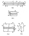
- An in Fig. 1 shown luminous element has a first glass tube 1, in which a coiled filament 2 is arranged. The two ends of the filament 2 are each connected to a terminal pin 3 and 4, which is melted into a glass tube 1 at the end closing glass block 5 and 6 respectively.
- the first glass tube 1 surrounds a second, to the first glass tube coaxial glass tube 7 with end walls 8 and 9, which are integrally connected to the first glass tube 1 and the glass blocks 5 and 6 respectively.
- a space 10 formed between the first and second glass tubes has an inlet 11 and an outlet 12 each in the form of a connecting piece.
- FIG. 2 While in the embodiment of Fig. 1 the inlet and outlet openings provided in the tube wall and the connecting pieces run perpendicular to the longitudinal axis of the glass tubes, has an in Fig. 2 shown light emitting element with a first glass tube 1 a and a second glass tube 7a at the end faces an inlet or outlet. In Fig. 2 the inlet 11a is shown on the front side 8a.
- Fig. 3 shows embodiments for lights, wherein on the left side of Fig. 3 a lamp with the in Fig. 1 shown arrangement of luminous element and shell and on the right side of Fig. 3 a lamp with the in Fig. 2 shown sheathed luminous element is shown.
- the inlet 11a on the end face 8a of the shell visible, and the housing 14 has correspondingly large openings 16th on the sides, through which the luminous element can be connected both electrically and to a coolant circuit.
- FIG. 1 When using the light element of Fig. 1 smaller openings 17 are provided in the side walls of the housing 13. A hose 18 connects the inlet and outlet of the light emitting element with an inlet or outlet on the housing. In Fig. 3 an outlet 19 is shown on the housing 13.
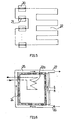
- Fig. 5 schematically shows a lighting system with lights 20 after 3 or 4 ,
- the interspersed with a coolant, such as water, interiors of the lighting elements 21 of the lights 20 are connected together in a series arrangement and are in communication with a heating element 22 in the form of a cooling coil.
- the heating element 22 may for example be embedded in the runway of an airfield. As heat supplier, all lights of the lighting system of the airfield could be included.
- buffers e.g. be provided with a water filling, to absorb heat.
- a heating element 22a corresponding to the heating element 22a may heat water in a hot water storage tank 23.
- the hot water storage tank 23 is surrounded by an array of parallel and series connected thermoelectric elements 24, which are exposed on the one hand the high temperature of the hot water tank 23 and on the other hand, the low temperature of a water circuit 25 with an inlet 26 and a drain 27.
- the thermocouples can be tapped at 28 electrical energy.
- Fig. 7 shows a further arrangement of a luminous element 1 b and a shell.
- the shell consists of a double tube with an outer tube 7b and an inner tube 28.
- the inner tube is directly against the light-emitting element 1b, so that the heat transfer from the light-emitting element 1b is not hindered in a space 10b through which coolant can flow.
- the light-emitting element 1 b can be pushed out of the inner tube 28 or into it. In the case of a defect of the luminous element, this can therefore easily be replaced.
Landscapes
- Arrangement Of Elements, Cooling, Sealing, Or The Like Of Lighting Devices (AREA)
- Non-Portable Lighting Devices Or Systems Thereof (AREA)
Abstract
Description
- Die Erfindung betrifft eine Leuchte mit einem Leuchtelement, das in einem Gehäuse angeordnet ist, welches einen Reflektor und ein Lichtaustrittsfenster umfasst, und mit Einrichtungen zur Abführung von Wärme von dem Leuchtelement.
- Aus der
FR-PS 904 049 - Der Erfindung liegt die Aufgabe zugrunde, eine neue Leuchte der eingangs erwähnten Art zu schaffen, die gegenüber herkömmlichen solchen Leuchten einen geringeren Wartungs- und Montageaufwand erfordert.
- Die diese Aufgabe lösende Leuchte nach der Erfindung ist dadurch gekennzeichnet, dass das Leuchtelement in einer Hülle eingeschlossen ist, welche einen Einlass und einen Auslass für ein zwischen dem Leuchtelement und der Innenwandfläche der Hülle strömendes Kühlmittel aufweist.
- Vorteilhaft bleibt die Durchströmung der Leuchte mit Kühlmittel auf die nähere Umgebung des Leuchtelements beschränkt. Die Leuchtkraft beeinträchtigende Ablagerungen am Reflektor werden vermieden. Die in der Umgebung des Leuchtelements konzentrierte Strömung entwickelt eine intensive, Ablagerungen am Leuchtelement bzw. der Hülle verhindernde Spülwirkung.
- Zweckmäßig sind Leuchtelement und Hülle in einer Baueinheit zusammengefasst und ggf. einstückig miteinander verbunden. So lässt sich die Leuchte bequem montieren.
- In einer bevorzugten Ausführungsform der Erfindung ist das Leuchtelement länglich und die Hülle umfasst eine das Leuchtmittel umgebende Röhre. Das Kühlmittel kann an einem Ende der Röhre in die Röhre ein- und am anderen Ende aus der Röhre ausströmen und dabei gleichmäßig Wärme von dem Leuchtmittel auf dessen gesamter Länge abführen.
- In der bevorzugten Ausführungsform weist das Leuchtelement an entgegengesetzten Enden jeweils einen elektrischen Anschlusskontakt auf. Vorzugsweise sind die Anschlusskontakte des Leuchtelements gegen den durchströmten Innenraum der Hülle elektrisch isoliert. Somit ist ein auf Elektrolyse basierender Stromfluss durch das Kühlmedium hindurch ausgeschlossen.
- Die Hülle kann aus Glas oder/und einem durchsichtigen Kunststoff bestehen.
- Der Ein- und Auslass können im Innenraum des Gehäuses angeordnet und Verbindungsleitungen zu einem Einlass bzw. Auslass am Gehäuse vorgesehen sein.
- Alternativ liegen der Einlass und der Auslass jeweils an einer Stirnseite der Hülle und, in Längsrichtung des Leuchtelements gesehen, innerhalb der Kontur einer Öffnung am Gehäuse.
- Die Leuchte bzw. das Leuchtelement kann Bestandteil einer Beleuchtungsanlage sein, die in Strömungsverbindung mit einem Heizelement steht. Beispielsweise können die Leuchten einer Flughafenbeleuchtung in Verbindung mit Heizelementen für die Start- und Landebahn stehen, durch die die Bahn schnee- und eisfrei gehalten wird.
- Das Heizelement kann zur Aufheizung eines Wärmespeichers dienen, wobei durch thermoelektrische Elemente eine Umwandlung der Wärmeenergie in elektrische Energie erfolgen kann.
- Die Erfindung wird nachfolgend anhand von Ausführungsbeispielen und der beiliegenden, sich auf diese Ausführungsbeispiele beziehenden Zeichnungen näher erläutert. Es zeigen:
- Fig. 1
- ein Leuchtelement mit einer Hülle in einem Längsschnitt gemäß einem ersten Ausführungsbeispiel für die vorliegende Erfindung,
- Fig. 2
- eine Teildarstellung eines Leuchtelements mit einer Hülle in einem Längsschnitt gemäß einem zweiten Ausführungsbeispiel für die Erfindung,
- Fig. 3
- eine erfindungsgemäße Leuchte mit einem umhüllten Leuchtelement gemäß
Fig. 1 bzw.Fig. 2 , - Fig. 4
- die Leuchte von
Fig. 3 in einer Seitenansicht, - Fig. 5
- eine Beleuchtungsanlage mit erfindungsgemäßen Leuchten, die in Strömungsverbindung mit einem Heizelement stehen,
- Fig. 6
- eine Anlage zur Rückgewinnung elektrischer Energie aus Wärme, die von Leuchten nach der Erfindung abgeführt worden ist, und
- Fig. 7
- ein weiteres Leuchtelement mit einer Hülle.
- Ein in
Fig. 1 gezeigtes Leuchtelement weist eine erste Glasröhre 1 auf, in der ein gewendelter Glühdraht 2 angeordnet ist. Die beiden Enden des Glühdrahts 2 sind jeweils mit einem Anschlusskontaktstift 3 bzw. 4 verbunden, welcher in einen die Glasröhre 1 endseitig verschließenden Glasblock 5 bzw. 6 eingeschmolzen ist. - Die erste Glasröhre 1 umgibt eine zweite, zu der ersten Glasröhre koaxiale Glasröhre 7 mit Stirnwänden 8 und 9, die einstückig mit der ersten Glasröhre 1 bzw. den Glasblöcken 5 und 6 verbunden sind. Ein zwischen der ersten und zweiten Glasröhre gebildeter Raum 10 weist einen Einlass 11 und einen Auslass 12 jeweils in Form eines Anschlussstutzens auf.
- Während bei dem Ausführungsbeispiel von
Fig. 1 die Ein- und Auslassöffnung in der Röhrenwand vorgesehen und die Anschlussstutzen senkrecht zur Längsachse der Glasröhren verlaufen, weist ein inFig. 2 gezeigtes Leuchtelement mit einer ersten Glasröhre 1 a und einer zweiten Glasröhre 7a an den Stirnseiten einen Einlass bzw. Auslass auf. InFig. 2 ist der Einlass 11a an der Stirnseite 8a gezeigt. -
Fig. 3 zeigt Ausführungsbeispiele für Leuchten, wobei auf der linken Seite vonFig. 3 eine Leuchte mit der inFig. 1 gezeigten Anordnung aus Leuchtelement und Hülle und auf der rechten Seite vonFig. 3 eine Leuchte mit dem inFig. 2 gezeigten umhüllten Leuchtelement dargestellt ist. - Dementsprechend ist in der Seitenansicht von
Fig. 4 der Einlass 11 a an der Stirnseite 8a der Hülle sichtbar, und das Gehäuse 14 weist entsprechend große Öffnungen 16 an den Seiten auf, durch die hindurch sich das Leuchtelement sowohl elektrisch als auch an einen Kühlmittelkreislauf anzuschließen lässt. - Bei Verwendung des Leuchtelements von
Fig. 1 sind kleinere Öffnungen 17 in den Seitenwänden des Gehäuses 13 vorgesehen. Ein Schlauch 18 verbindet den Ein- bzw. Auslass des Leuchtelements mit einem Einlass bzw. Auslass am Gehäuse. InFig. 3 ist ein Auslass 19 am Gehäuse 13 gezeigt. -
Fig. 5 zeigt schematisch eine Beleuchtungsanlage mit Leuchten 20 nachFig. 3 oder 4 . Die mit einem Kühlmittel, z.B. Wasser, durchströmbaren Innenräume der Leuchtelemente 21 der Leuchten 20 sind in einer Reihenanordnung miteinander verbunden und stehen in Verbindung mit einem Heizelement 22 in Form einer Kühlschlange. Das Heizelement 22 kann z.B. in der Start- und Landebahn eines Flugplatzes eingebettet sein. Als Wärmelieferanten ließen sich sämtliche Leuchten der Beleuchtungsanlage des Flugplatzes einbeziehen. - Es versteht sich, dass Reihen- und Parallelschaltungen der Leuchten miteinander kombiniert werden können.
- Ferner könnten Zwischenspeicher, z.B. mit einer Wasserfüllung, zur Aufnahme von Wärme vorgesehen sein.
- Gemäß
Fig. 4 kann ein dem Heizelement 22 entsprechendes Heizelement 22a Wasser in einem Heißwasserspeicher 23 aufheizen. Der Heißwasserspeicher 23 ist von einer Anordnung parallel und in Reihe geschalteter thermoelektrischer Elemente 24 umgeben, welche einerseits der hohen Temperatur des Heißwasserspeichers 23 und andererseits der niedrigen Temperatur eines Wasserkreislaufs 25 mit einem Zulauf 26 und einem Ablauf 27 ausgesetzt sind. An den Thermoelementen lässt sich bei 28 elektrische Energie abgreifen. -
Fig. 7 zeigt eine weitere Anordnung aus einem Leuchtelement 1 b und einer Hülle. Die Hülle besteht aus einem Doppelrohr mit einer Außenröhre 7b und einer Innenröhre 28. Die Innenröhre liegt unmittelbar gegen das Leuchtelement 1 b an, so dass der Wärmedurchgang vom Leuchtelement 1 b in einen mit Kühlmittel durchströmbaren Raum 10b nicht behindert ist. Das Leuchtelement 1 b lässt sich aus der innenröhre 28 heraus bzw. in diese hineinschieben. Bei einem Defekt des Leuchtelements lässt sich dieses daher leicht auswechseln.
Claims (15)
- Leuchte mit einem Leuchtelement (1), das in einem Gehäuse (13) angeordnet ist, welches einen Reflektor (14) und ein Lichtaustrittsfenster (15) umfasst und mit Einrichtungen zur Abführung von Wärme von dem Leuchtelement (1),
dadurch gekennzeichnet,
dass das Leuchtelement (1) in einer Hülle (7-9) eingeschlossen ist, welche einen Einlass (11) und einen Auslass (12) für ein zwischen dem Leuchtelement (1) und der Innenwandfläche der Hülle (7-9) strömendes Kühlmittel aufweist. - Leuchte nach Anspruch 1,
dadurch gekennzeichnet,
dass das Leuchtelement (1) und die Hülle (7-9) in einer Baueinheit (21) zusammengefasst sind. - Leuchte nach Anspruch 1 oder 2,
dadurch gekennzeichnet,
dass das Leuchtelement (1) länglich und die Hülle (7-9) eine das Leuchtelement (1) umgebenden Röhre (7) umfasst. - Leuchte nach einem der Ansprüche 1 bis 3,
dadurch gekennzeichnet,
dass das Leuchtelement (1) an entgegengesetzten Enden jeweils einen Anschlusskontakt (3,4) aufweist. - Leuchte nach einem der Ansprüche 1 bis 4,
dadurch gekennzeichnet,
dass die Anschlusskontakte (3,4) des Leuchtelements (1) gegen den durchströmten Innenraum (10) der Hülle (7-9) elektrisch isoliert sind. - Leuchte nach einem der Ansprüche 1 bis 5,
dadurch gekennzeichnet,
dass die Hülle (7-9) Glas oder/und einen Kunststoff aufweist. - Leuchte nach einem der Ansprüche 1 bis 6,
dadurch gekennzeichnet,
dass der Ein- und Auslass (11,12) im Innenraum des Gehäuses (13) angeordnet und Verbindungsleitungen (18) zu einem Einlass bzw. Auslass am Gehäuse (13) vorgesehen sind. - Leuchte nach einem der Ansprüche 1 bis 7,
dadurch gekennzeichnet,
dass der Einlass (11 a) und der Auslass in Längsrichtung des Leuchtelements gesehen innerhalb der Kontur einer Öffnung (16) im Gehäuse (13) liegen. - Leuchte nach einem der Ansprüche 1 bis 8,
dadurch gekennzeichnet,
dass die Hülle ein Doppelrohr mit einer Außenröhre (7b) und einer Innenröhre (28) umfasst, wobei die Innenröhre (28) gegen das Leuchtelement (1b) anliegt und das Leuchtelement (1 b) in der Innenröhre (28) verschiebbar ist. - Baueinheit mit einem Leuchtelement (1) und einer Hülle (7-9) für eine Leuchte nach einem der Ansprüche 1 bis 9.
- Beleuchtungsanlage mit wenigstens einer Leuchte (20) nach einem der Ansprüche 1 bis 10.
- Beleuchtungsanlage nach Anspruch 11,
dadurch gekennzeichnet,
dass die wenigstens eine Leuchte (20) in Strömungsverbindung mit einem Heizelement (22) steht. - Beleuchtungsanlage nach Anspruch 11,
dadurch gekennzeichnet,
dass das Heizelement (22) zur Beheizung einer Start- und Landebahn auf einem Flugplatz vorgesehen ist. - Beleuchtungsanlage nach einem der Ansprüche 11 bis 13,
dadurch gekennzeichnet,
dass das Heizelement (22a) zur Übertragung von Wärme an einen Wärmespeicher (23) vorgesehen ist. - Beleuchtungsanlage nach Anspruch 14,
dadurch gekennzeichnet,
dass thermoelektrische Elemente (24) zur Umwandlung in dem Wärmespeicher (23) gespeicherter Wärme in elektrische Energie vorgesehen sind.
Priority Applications (2)
| Application Number | Priority Date | Filing Date | Title |
|---|---|---|---|
| PL08004150T PL1968101T3 (pl) | 2007-03-06 | 2008-03-06 | Oprawa oświetleniowa z urządzeniem do chłodzenia żarówki |
| EP11002268A EP2365516A1 (de) | 2007-03-06 | 2008-03-06 | Beleuchtungsanlage für einen Flugplatz mit Einrichtung zur Kühlung der Lampe |
Applications Claiming Priority (1)
| Application Number | Priority Date | Filing Date | Title |
|---|---|---|---|
| DE102007011260A DE102007011260A1 (de) | 2007-03-06 | 2007-03-06 | Leuchte |
Related Child Applications (1)
| Application Number | Title | Priority Date | Filing Date |
|---|---|---|---|
| EP11002268A Division-Into EP2365516A1 (de) | 2007-03-06 | 2008-03-06 | Beleuchtungsanlage für einen Flugplatz mit Einrichtung zur Kühlung der Lampe |
Publications (3)
| Publication Number | Publication Date |
|---|---|
| EP1968101A2 true EP1968101A2 (de) | 2008-09-10 |
| EP1968101A3 EP1968101A3 (de) | 2009-07-29 |
| EP1968101B1 EP1968101B1 (de) | 2012-09-26 |
Family
ID=39587020
Family Applications (2)
| Application Number | Title | Priority Date | Filing Date |
|---|---|---|---|
| EP11002268A Withdrawn EP2365516A1 (de) | 2007-03-06 | 2008-03-06 | Beleuchtungsanlage für einen Flugplatz mit Einrichtung zur Kühlung der Lampe |
| EP08004150A Not-in-force EP1968101B1 (de) | 2007-03-06 | 2008-03-06 | Leuchte mit Einrichtung zur Kühlung der Lampe |
Family Applications Before (1)
| Application Number | Title | Priority Date | Filing Date |
|---|---|---|---|
| EP11002268A Withdrawn EP2365516A1 (de) | 2007-03-06 | 2008-03-06 | Beleuchtungsanlage für einen Flugplatz mit Einrichtung zur Kühlung der Lampe |
Country Status (4)
| Country | Link |
|---|---|
| EP (2) | EP2365516A1 (de) |
| DE (1) | DE102007011260A1 (de) |
| DK (1) | DK1968101T3 (de) |
| PL (1) | PL1968101T3 (de) |
Cited By (1)
| Publication number | Priority date | Publication date | Assignee | Title |
|---|---|---|---|---|
| DE102011012035A1 (de) | 2011-02-22 | 2012-08-23 | Werner Quinten | Vorrichtung zur Beheizung einer Flugzeugstart- und -landebahn |
Citations (1)
| Publication number | Priority date | Publication date | Assignee | Title |
|---|---|---|---|---|
| FR904049A (fr) | 1943-12-09 | 1945-10-24 | Thomson Houston Comp Francaise | Dispositif d'éclairage électrique à refroidissement par liquide |
Family Cites Families (15)
| Publication number | Priority date | Publication date | Assignee | Title |
|---|---|---|---|---|
| FR648623A (fr) | 1928-02-10 | 1928-12-12 | Anciens Ets Barbier | Perfectionnements aux appareils d'éclairage sans ombres portées |
| US2105430A (en) * | 1929-09-18 | 1938-01-11 | Gen Electric | Electric lamp |
| DE707528C (de) | 1938-03-08 | 1941-06-25 | Hugo Schneider Akt Ges | Kuehlvorrichtung fuer insbesondere an Scheinwerfern angebrachte Polarisationseinrichtungen |
| DE740922C (de) * | 1939-03-21 | 1943-10-30 | Patra Patent Treuhand | Anordnung zum Betrieb einer wassergekuehlten Quecksilberhochdruckentladungslampe |
| US2346304A (en) * | 1940-05-20 | 1944-04-11 | Eulalia C Henderson | Aviation landing field |
| US2572451A (en) * | 1947-04-08 | 1951-10-23 | Warren A Custer | Lighting means and systems for airplane landing runways |
| US2588154A (en) * | 1947-07-15 | 1952-03-04 | American Gas Accumulator Compa | High-intensity lighting unit |
| US3567917A (en) * | 1968-08-06 | 1971-03-02 | Structural Electric Products C | Runway light |
| US3869605A (en) * | 1970-06-24 | 1975-03-04 | Integrated Dev & Manufacturing | Environmental growth control apparatus |
| US4877991A (en) * | 1987-12-21 | 1989-10-31 | Colterjohn Jr Walter L | Optical radiation source |
| US6443596B1 (en) * | 1998-03-27 | 2002-09-03 | Hill-Rom Services, Inc. | Surgical light apparatus with improved cooling |
| WO2001065676A1 (fr) * | 2000-03-02 | 2001-09-07 | Baret Marie Therese | Dispositif pour chauffer et eclairer des pistes d'aviation au moyen de l'energie solaire |
| US20020145875A1 (en) * | 2001-04-10 | 2002-10-10 | Perkinelmer Optoelectronics N.C., Inc. | Compact water-cooled multi-kilowatt lamp |
| US20050000559A1 (en) * | 2003-03-24 | 2005-01-06 | Yuma Horio | Thermoelectric generator |
| DE102004041956A1 (de) | 2004-08-31 | 2006-03-02 | Quinten, Margret | Beleuchtungseinheit |
-
2007
- 2007-03-06 DE DE102007011260A patent/DE102007011260A1/de not_active Withdrawn
-
2008
- 2008-03-06 DK DK08004150.2T patent/DK1968101T3/da active
- 2008-03-06 PL PL08004150T patent/PL1968101T3/pl unknown
- 2008-03-06 EP EP11002268A patent/EP2365516A1/de not_active Withdrawn
- 2008-03-06 EP EP08004150A patent/EP1968101B1/de not_active Not-in-force
Patent Citations (1)
| Publication number | Priority date | Publication date | Assignee | Title |
|---|---|---|---|---|
| FR904049A (fr) | 1943-12-09 | 1945-10-24 | Thomson Houston Comp Francaise | Dispositif d'éclairage électrique à refroidissement par liquide |
Cited By (1)
| Publication number | Priority date | Publication date | Assignee | Title |
|---|---|---|---|---|
| DE102011012035A1 (de) | 2011-02-22 | 2012-08-23 | Werner Quinten | Vorrichtung zur Beheizung einer Flugzeugstart- und -landebahn |
Also Published As
| Publication number | Publication date |
|---|---|
| DE102007011260A1 (de) | 2008-09-11 |
| EP1968101A3 (de) | 2009-07-29 |
| EP2365516A1 (de) | 2011-09-14 |
| PL1968101T3 (pl) | 2013-02-28 |
| DK1968101T3 (da) | 2013-01-07 |
| EP1968101B1 (de) | 2012-09-26 |
Similar Documents
| Publication | Publication Date | Title |
|---|---|---|
| DE3005017C2 (de) | ||
| DE102007030186B4 (de) | Lineare LED-Lampe und Leuchtensystem mit derselben | |
| WO1997044612A1 (de) | Leuchteinrichtung für flughäfen, insbesondere unterflurfeuer | |
| WO2013135527A1 (de) | Leuchtdiodenlampe und verfahren zum fertigen einer leuchtdiodenlampe | |
| DE4014918C2 (de) | ||
| DE19822829A1 (de) | Kurzwelliger Infrarot-Flächenstrahler | |
| EP1968101B1 (de) | Leuchte mit Einrichtung zur Kühlung der Lampe | |
| DE10209905B4 (de) | Elektrisches Heizgerät, insbesondere Durchlauferhitzer | |
| WO2010052538A1 (de) | Led-beleuchtungsvorrichtung, insbesondere für tunnels | |
| DE102008056498A1 (de) | Unterwasserscheinwerfer | |
| DE102019104999A1 (de) | Scheinwerfer, insbesondere Kraftfahrzeugscheinwerfer | |
| DE202017102535U1 (de) | Ladekabel für Elektrofahrzeuge | |
| DE102007047271A1 (de) | Leuchte zur Unterwasser-Illumination | |
| DE202017106579U1 (de) | Nahtlose Verbindung ermöglichende LED-Leuchte mit weitwinkliger Abstrahlung | |
| DE69703594T2 (de) | Durch Wärmeleitung gekühlter Blitzlampe | |
| DE19603025A1 (de) | Lichtgenerator zur Einspeisung in Lichtleitfasern | |
| DE102007040076B4 (de) | Heizrohranordnung | |
| EP1611773B1 (de) | Strahlermodul | |
| DE19643784A1 (de) | Leuchtmittel | |
| DE102006041959A1 (de) | Beleuchtungssystem zum Erzeugen von Licht und zum Einkoppeln des Lichts in ein proximales Ende eines Lichtleitkabels einer Beobachtungsvorrichtung für die Endoskopie oder Mikroskopie | |
| DE202010005528U1 (de) | Leuchte | |
| DE102014217043B4 (de) | Kraftfahrzeug-Beleuchtungsvorrichtung | |
| DE19843059C2 (de) | Verfahren zum Temperieren einer Halogenlampe, Temperierelement und dessen Verwendung | |
| DE102023109084A1 (de) | Kabelbaugruppe | |
| DE19581852B4 (de) | Strahlungsprojektor und Verfahren zu dessen Herstellung |
Legal Events
| Date | Code | Title | Description |
|---|---|---|---|
| PUAI | Public reference made under article 153(3) epc to a published international application that has entered the european phase |
Free format text: ORIGINAL CODE: 0009012 |
|
| AK | Designated contracting states |
Kind code of ref document: A2 Designated state(s): AT BE BG CH CY CZ DE DK EE ES FI FR GB GR HR HU IE IS IT LI LT LU LV MC MT NL NO PL PT RO SE SI SK TR |
|
| AX | Request for extension of the european patent |
Extension state: AL BA MK RS |
|
| PUAL | Search report despatched |
Free format text: ORIGINAL CODE: 0009013 |
|
| AK | Designated contracting states |
Kind code of ref document: A3 Designated state(s): AT BE BG CH CY CZ DE DK EE ES FI FR GB GR HR HU IE IS IT LI LT LU LV MC MT NL NO PL PT RO SE SI SK TR |
|
| AX | Request for extension of the european patent |
Extension state: AL BA MK RS |
|
| RIC1 | Information provided on ipc code assigned before grant |
Ipc: F21V 29/02 20060101ALI20090623BHEP Ipc: H01K 1/58 20060101ALI20090623BHEP Ipc: F21S 8/00 20060101ALI20090623BHEP Ipc: H02N 11/00 20060101ALI20090623BHEP Ipc: H01J 61/52 20060101AFI20080716BHEP Ipc: B64F 1/20 20060101ALI20090623BHEP |
|
| 17P | Request for examination filed |
Effective date: 20100115 |
|
| 17Q | First examination report despatched |
Effective date: 20100215 |
|
| AKX | Designation fees paid |
Designated state(s): AT BE BG CH CY CZ DE DK EE ES FI FR GB GR HR HU IE IS IT LI LT LU LV MC MT NL NO PL PT RO SE SI SK TR |
|
| REG | Reference to a national code |
Ref country code: DE Ref legal event code: R079 Ref document number: 502008008239 Country of ref document: DE Free format text: PREVIOUS MAIN CLASS: H01J0061520000 Ipc: H01L0035300000 |
|
| GRAP | Despatch of communication of intention to grant a patent |
Free format text: ORIGINAL CODE: EPIDOSNIGR1 |
|
| RIC1 | Information provided on ipc code assigned before grant |
Ipc: H01K 1/58 20060101ALI20111121BHEP Ipc: H01J 61/52 20060101ALI20111121BHEP Ipc: H01L 35/30 20060101AFI20111121BHEP |
|
| RIC1 | Information provided on ipc code assigned before grant |
Ipc: H01K 1/58 20060101ALI20111219BHEP Ipc: F21S 8/00 20060101ALI20111219BHEP Ipc: H02N 11/00 20060101ALI20111219BHEP Ipc: B64F 1/20 20060101ALI20111219BHEP Ipc: F21V 29/02 20060101ALI20111219BHEP Ipc: H01J 61/52 20060101ALI20111219BHEP Ipc: H01L 35/30 20060101AFI20111219BHEP |
|
| GRAS | Grant fee paid |
Free format text: ORIGINAL CODE: EPIDOSNIGR3 |
|
| GRAA | (expected) grant |
Free format text: ORIGINAL CODE: 0009210 |
|
| AK | Designated contracting states |
Kind code of ref document: B1 Designated state(s): AT BE BG CH CY CZ DE DK EE ES FI FR GB GR HR HU IE IS IT LI LT LU LV MC MT NL NO PL PT RO SE SI SK TR |
|
| REG | Reference to a national code |
Ref country code: GB Ref legal event code: FG4D Free format text: NOT ENGLISH |
|
| REG | Reference to a national code |
Ref country code: CH Ref legal event code: EP |
|
| REG | Reference to a national code |
Ref country code: AT Ref legal event code: REF Ref document number: 577381 Country of ref document: AT Kind code of ref document: T Effective date: 20121015 |
|
| REG | Reference to a national code |
Ref country code: IE Ref legal event code: FG4D Free format text: LANGUAGE OF EP DOCUMENT: GERMAN |
|
| REG | Reference to a national code |
Ref country code: DE Ref legal event code: R096 Ref document number: 502008008239 Country of ref document: DE Effective date: 20121122 |
|
| REG | Reference to a national code |
Ref country code: CH Ref legal event code: NV Representative=s name: ALDO ROEMPLER PATENTANWALT, CH |
|
| REG | Reference to a national code |
Ref country code: DK Ref legal event code: T3 |
|
| REG | Reference to a national code |
Ref country code: NL Ref legal event code: T3 |
|
| PG25 | Lapsed in a contracting state [announced via postgrant information from national office to epo] |
Ref country code: NO Free format text: LAPSE BECAUSE OF FAILURE TO SUBMIT A TRANSLATION OF THE DESCRIPTION OR TO PAY THE FEE WITHIN THE PRESCRIBED TIME-LIMIT Effective date: 20121226 Ref country code: FI Free format text: LAPSE BECAUSE OF FAILURE TO SUBMIT A TRANSLATION OF THE DESCRIPTION OR TO PAY THE FEE WITHIN THE PRESCRIBED TIME-LIMIT Effective date: 20120926 Ref country code: LT Free format text: LAPSE BECAUSE OF FAILURE TO SUBMIT A TRANSLATION OF THE DESCRIPTION OR TO PAY THE FEE WITHIN THE PRESCRIBED TIME-LIMIT Effective date: 20120926 Ref country code: HR Free format text: LAPSE BECAUSE OF FAILURE TO SUBMIT A TRANSLATION OF THE DESCRIPTION OR TO PAY THE FEE WITHIN THE PRESCRIBED TIME-LIMIT Effective date: 20120926 |
|
| REG | Reference to a national code |
Ref country code: LT Ref legal event code: MG4D Effective date: 20120926 |
|
| PG25 | Lapsed in a contracting state [announced via postgrant information from national office to epo] |
Ref country code: GR Free format text: LAPSE BECAUSE OF FAILURE TO SUBMIT A TRANSLATION OF THE DESCRIPTION OR TO PAY THE FEE WITHIN THE PRESCRIBED TIME-LIMIT Effective date: 20121227 Ref country code: LV Free format text: LAPSE BECAUSE OF FAILURE TO SUBMIT A TRANSLATION OF THE DESCRIPTION OR TO PAY THE FEE WITHIN THE PRESCRIBED TIME-LIMIT Effective date: 20120926 Ref country code: SI Free format text: LAPSE BECAUSE OF FAILURE TO SUBMIT A TRANSLATION OF THE DESCRIPTION OR TO PAY THE FEE WITHIN THE PRESCRIBED TIME-LIMIT Effective date: 20120926 Ref country code: SE Free format text: LAPSE BECAUSE OF FAILURE TO SUBMIT A TRANSLATION OF THE DESCRIPTION OR TO PAY THE FEE WITHIN THE PRESCRIBED TIME-LIMIT Effective date: 20120926 |
|
| REG | Reference to a national code |
Ref country code: PL Ref legal event code: T3 |
|
| PG25 | Lapsed in a contracting state [announced via postgrant information from national office to epo] |
Ref country code: IS Free format text: LAPSE BECAUSE OF FAILURE TO SUBMIT A TRANSLATION OF THE DESCRIPTION OR TO PAY THE FEE WITHIN THE PRESCRIBED TIME-LIMIT Effective date: 20130126 Ref country code: ES Free format text: LAPSE BECAUSE OF FAILURE TO SUBMIT A TRANSLATION OF THE DESCRIPTION OR TO PAY THE FEE WITHIN THE PRESCRIBED TIME-LIMIT Effective date: 20130106 Ref country code: RO Free format text: LAPSE BECAUSE OF FAILURE TO SUBMIT A TRANSLATION OF THE DESCRIPTION OR TO PAY THE FEE WITHIN THE PRESCRIBED TIME-LIMIT Effective date: 20120926 Ref country code: EE Free format text: LAPSE BECAUSE OF FAILURE TO SUBMIT A TRANSLATION OF THE DESCRIPTION OR TO PAY THE FEE WITHIN THE PRESCRIBED TIME-LIMIT Effective date: 20120926 |
|
| PG25 | Lapsed in a contracting state [announced via postgrant information from national office to epo] |
Ref country code: SK Free format text: LAPSE BECAUSE OF FAILURE TO SUBMIT A TRANSLATION OF THE DESCRIPTION OR TO PAY THE FEE WITHIN THE PRESCRIBED TIME-LIMIT Effective date: 20120926 Ref country code: PT Free format text: LAPSE BECAUSE OF FAILURE TO SUBMIT A TRANSLATION OF THE DESCRIPTION OR TO PAY THE FEE WITHIN THE PRESCRIBED TIME-LIMIT Effective date: 20130128 Ref country code: CY Free format text: LAPSE BECAUSE OF FAILURE TO SUBMIT A TRANSLATION OF THE DESCRIPTION OR TO PAY THE FEE WITHIN THE PRESCRIBED TIME-LIMIT Effective date: 20120926 |
|
| PG25 | Lapsed in a contracting state [announced via postgrant information from national office to epo] |
Ref country code: BG Free format text: LAPSE BECAUSE OF FAILURE TO SUBMIT A TRANSLATION OF THE DESCRIPTION OR TO PAY THE FEE WITHIN THE PRESCRIBED TIME-LIMIT Effective date: 20121226 |
|
| PLBE | No opposition filed within time limit |
Free format text: ORIGINAL CODE: 0009261 |
|
| STAA | Information on the status of an ep patent application or granted ep patent |
Free format text: STATUS: NO OPPOSITION FILED WITHIN TIME LIMIT |
|
| PG25 | Lapsed in a contracting state [announced via postgrant information from national office to epo] |
Ref country code: IT Free format text: LAPSE BECAUSE OF FAILURE TO SUBMIT A TRANSLATION OF THE DESCRIPTION OR TO PAY THE FEE WITHIN THE PRESCRIBED TIME-LIMIT Effective date: 20120926 |
|
| 26N | No opposition filed |
Effective date: 20130627 |
|
| REG | Reference to a national code |
Ref country code: DE Ref legal event code: R097 Ref document number: 502008008239 Country of ref document: DE Effective date: 20130627 |
|
| PG25 | Lapsed in a contracting state [announced via postgrant information from national office to epo] |
Ref country code: MC Free format text: LAPSE BECAUSE OF NON-PAYMENT OF DUE FEES Effective date: 20130331 |
|
| REG | Reference to a national code |
Ref country code: IE Ref legal event code: MM4A |
|
| PG25 | Lapsed in a contracting state [announced via postgrant information from national office to epo] |
Ref country code: IE Free format text: LAPSE BECAUSE OF NON-PAYMENT OF DUE FEES Effective date: 20130306 |
|
| REG | Reference to a national code |
Ref country code: DE Ref legal event code: R082 Ref document number: 502008008239 Country of ref document: DE Representative=s name: PATENTANWAELTE BERNHARDT/WOLFF PARTNERSCHAFT, DE |
|
| PG25 | Lapsed in a contracting state [announced via postgrant information from national office to epo] |
Ref country code: MT Free format text: LAPSE BECAUSE OF FAILURE TO SUBMIT A TRANSLATION OF THE DESCRIPTION OR TO PAY THE FEE WITHIN THE PRESCRIBED TIME-LIMIT Effective date: 20120926 |
|
| REG | Reference to a national code |
Ref country code: FR Ref legal event code: PLFP Year of fee payment: 8 |
|
| PGFP | Annual fee paid to national office [announced via postgrant information from national office to epo] |
Ref country code: DK Payment date: 20150325 Year of fee payment: 8 Ref country code: NL Payment date: 20150323 Year of fee payment: 8 Ref country code: CZ Payment date: 20150225 Year of fee payment: 8 Ref country code: LU Payment date: 20150312 Year of fee payment: 8 Ref country code: CH Payment date: 20150303 Year of fee payment: 8 Ref country code: DE Payment date: 20150304 Year of fee payment: 8 |
|
| PGFP | Annual fee paid to national office [announced via postgrant information from national office to epo] |
Ref country code: GB Payment date: 20150324 Year of fee payment: 8 Ref country code: AT Payment date: 20150320 Year of fee payment: 8 Ref country code: FR Payment date: 20150310 Year of fee payment: 8 Ref country code: PL Payment date: 20150209 Year of fee payment: 8 |
|
| PG25 | Lapsed in a contracting state [announced via postgrant information from national office to epo] |
Ref country code: TR Free format text: LAPSE BECAUSE OF FAILURE TO SUBMIT A TRANSLATION OF THE DESCRIPTION OR TO PAY THE FEE WITHIN THE PRESCRIBED TIME-LIMIT Effective date: 20120926 |
|
| PG25 | Lapsed in a contracting state [announced via postgrant information from national office to epo] |
Ref country code: HU Free format text: LAPSE BECAUSE OF FAILURE TO SUBMIT A TRANSLATION OF THE DESCRIPTION OR TO PAY THE FEE WITHIN THE PRESCRIBED TIME-LIMIT; INVALID AB INITIO Effective date: 20080306 |
|
| PGFP | Annual fee paid to national office [announced via postgrant information from national office to epo] |
Ref country code: BE Payment date: 20150318 Year of fee payment: 8 |
|
| PG25 | Lapsed in a contracting state [announced via postgrant information from national office to epo] |
Ref country code: BE Free format text: LAPSE BECAUSE OF NON-PAYMENT OF DUE FEES Effective date: 20160331 |
|
| REG | Reference to a national code |
Ref country code: DE Ref legal event code: R119 Ref document number: 502008008239 Country of ref document: DE |
|
| REG | Reference to a national code |
Ref country code: DK Ref legal event code: EBP Effective date: 20160331 |
|
| PG25 | Lapsed in a contracting state [announced via postgrant information from national office to epo] |
Ref country code: LU Free format text: LAPSE BECAUSE OF NON-PAYMENT OF DUE FEES Effective date: 20160306 |
|
| REG | Reference to a national code |
Ref country code: CH Ref legal event code: PL |
|
| REG | Reference to a national code |
Ref country code: AT Ref legal event code: MM01 Ref document number: 577381 Country of ref document: AT Kind code of ref document: T Effective date: 20160306 |
|
| REG | Reference to a national code |
Ref country code: NL Ref legal event code: MM Effective date: 20160401 |
|
| GBPC | Gb: european patent ceased through non-payment of renewal fee |
Effective date: 20160306 |
|
| PG25 | Lapsed in a contracting state [announced via postgrant information from national office to epo] |
Ref country code: CZ Free format text: LAPSE BECAUSE OF NON-PAYMENT OF DUE FEES Effective date: 20160306 |
|
| REG | Reference to a national code |
Ref country code: FR Ref legal event code: ST Effective date: 20161130 |
|
| PG25 | Lapsed in a contracting state [announced via postgrant information from national office to epo] |
Ref country code: LI Free format text: LAPSE BECAUSE OF NON-PAYMENT OF DUE FEES Effective date: 20160331 Ref country code: NL Free format text: LAPSE BECAUSE OF NON-PAYMENT OF DUE FEES Effective date: 20160401 Ref country code: CH Free format text: LAPSE BECAUSE OF NON-PAYMENT OF DUE FEES Effective date: 20160331 Ref country code: GB Free format text: LAPSE BECAUSE OF NON-PAYMENT OF DUE FEES Effective date: 20160306 Ref country code: DE Free format text: LAPSE BECAUSE OF NON-PAYMENT OF DUE FEES Effective date: 20161001 Ref country code: FR Free format text: LAPSE BECAUSE OF NON-PAYMENT OF DUE FEES Effective date: 20160331 |
|
| PG25 | Lapsed in a contracting state [announced via postgrant information from national office to epo] |
Ref country code: AT Free format text: LAPSE BECAUSE OF NON-PAYMENT OF DUE FEES Effective date: 20160306 |
|
| PG25 | Lapsed in a contracting state [announced via postgrant information from national office to epo] |
Ref country code: DK Free format text: LAPSE BECAUSE OF NON-PAYMENT OF DUE FEES Effective date: 20160331 |
|
| PG25 | Lapsed in a contracting state [announced via postgrant information from national office to epo] |
Ref country code: PL Free format text: LAPSE BECAUSE OF NON-PAYMENT OF DUE FEES Effective date: 20160306 |