EP1968048A1 - Support de stockage optique et appareil de lecture des données respectives - Google Patents
Support de stockage optique et appareil de lecture des données respectives Download PDFInfo
- Publication number
- EP1968048A1 EP1968048A1 EP07103729A EP07103729A EP1968048A1 EP 1968048 A1 EP1968048 A1 EP 1968048A1 EP 07103729 A EP07103729 A EP 07103729A EP 07103729 A EP07103729 A EP 07103729A EP 1968048 A1 EP1968048 A1 EP 1968048A1
- Authority
- EP
- European Patent Office
- Prior art keywords
- partitioned
- storage medium
- marks
- optical storage
- optical
- Prior art date
- Legal status (The legal status is an assumption and is not a legal conclusion. Google has not performed a legal analysis and makes no representation as to the accuracy of the status listed.)
- Pending
Links
- 230000003287 optical effect Effects 0.000 title claims abstract description 94
- 230000005669 field effect Effects 0.000 claims abstract description 6
- 239000000463 material Substances 0.000 claims abstract 2
- 238000001514 detection method Methods 0.000 claims description 5
- 238000000638 solvent extraction Methods 0.000 claims description 3
- 239000007787 solid Substances 0.000 claims description 2
- 230000000063 preceeding effect Effects 0.000 claims 4
- 238000005192 partition Methods 0.000 abstract description 2
- 230000010287 polarization Effects 0.000 description 30
- 239000010410 layer Substances 0.000 description 14
- 230000033228 biological regulation Effects 0.000 description 4
- 230000000694 effects Effects 0.000 description 4
- 239000011248 coating agent Substances 0.000 description 2
- 238000000576 coating method Methods 0.000 description 2
- 230000005684 electric field Effects 0.000 description 2
- 239000012782 phase change material Substances 0.000 description 2
- 238000002310 reflectometry Methods 0.000 description 2
- 229910000763 AgInSbTe Inorganic materials 0.000 description 1
- 229910000618 GeSbTe Inorganic materials 0.000 description 1
- 229910052782 aluminium Inorganic materials 0.000 description 1
- XAGFODPZIPBFFR-UHFFFAOYSA-N aluminium Chemical compound [Al] XAGFODPZIPBFFR-UHFFFAOYSA-N 0.000 description 1
- 150000001875 compounds Chemical class 0.000 description 1
- 239000002355 dual-layer Substances 0.000 description 1
- 238000005516 engineering process Methods 0.000 description 1
- 238000005286 illumination Methods 0.000 description 1
- 238000004519 manufacturing process Methods 0.000 description 1
- 238000005259 measurement Methods 0.000 description 1
- 229910044991 metal oxide Inorganic materials 0.000 description 1
- 150000004706 metal oxides Chemical class 0.000 description 1
- 229920000642 polymer Polymers 0.000 description 1
- 239000000758 substrate Substances 0.000 description 1
Images
Classifications
-
- G—PHYSICS
- G11—INFORMATION STORAGE
- G11B—INFORMATION STORAGE BASED ON RELATIVE MOVEMENT BETWEEN RECORD CARRIER AND TRANSDUCER
- G11B7/00—Recording or reproducing by optical means, e.g. recording using a thermal beam of optical radiation by modifying optical properties or the physical structure, reproducing using an optical beam at lower power by sensing optical properties; Record carriers therefor
- G11B7/24—Record carriers characterised by shape, structure or physical properties, or by the selection of the material
- G11B7/2407—Tracks or pits; Shape, structure or physical properties thereof
- G11B7/24085—Pits
-
- G—PHYSICS
- G11—INFORMATION STORAGE
- G11B—INFORMATION STORAGE BASED ON RELATIVE MOVEMENT BETWEEN RECORD CARRIER AND TRANSDUCER
- G11B7/00—Recording or reproducing by optical means, e.g. recording using a thermal beam of optical radiation by modifying optical properties or the physical structure, reproducing using an optical beam at lower power by sensing optical properties; Record carriers therefor
- G11B7/08—Disposition or mounting of heads or light sources relatively to record carriers
- G11B7/09—Disposition or mounting of heads or light sources relatively to record carriers with provision for moving the light beam or focus plane for the purpose of maintaining alignment of the light beam relative to the record carrier during transducing operation, e.g. to compensate for surface irregularities of the latter or for track following
- G11B7/0901—Disposition or mounting of heads or light sources relatively to record carriers with provision for moving the light beam or focus plane for the purpose of maintaining alignment of the light beam relative to the record carrier during transducing operation, e.g. to compensate for surface irregularities of the latter or for track following for track following only
-
- G—PHYSICS
- G11—INFORMATION STORAGE
- G11B—INFORMATION STORAGE BASED ON RELATIVE MOVEMENT BETWEEN RECORD CARRIER AND TRANSDUCER
- G11B7/00—Recording or reproducing by optical means, e.g. recording using a thermal beam of optical radiation by modifying optical properties or the physical structure, reproducing using an optical beam at lower power by sensing optical properties; Record carriers therefor
- G11B7/24—Record carriers characterised by shape, structure or physical properties, or by the selection of the material
- G11B7/2407—Tracks or pits; Shape, structure or physical properties thereof
- G11B7/24073—Tracks
- G11B7/24079—Width or depth
Definitions
- the present invention relates to an optical storage medium, in particular an optical disc comprising a super resolution near field structure for storing of data with a high data density in a read only region, and to an apparatus for reading of respective data from the storage medium.
- Optical storage media are media in which data are stored in an optically readable manner, for example by means of a pickup comprising a laser for illuminating the optical storage medium and a photo-detector for detecting the reflected light of the laser beam when reading the data.
- a large variety of optical storage media are known, which are operated with different laser wavelength, and which have different sizes for providing storage capacities from below one Gigabyte up to 50 Gigabyte (GB).
- the formats include read-only formats such as Audio CD and Video DVD, write-once optical media as well as rewritable formats like CD-RW, DVD-RW, DVD+RW and DVD-RAM for example. Digital data are stored in these media along tracks in one or more layers of the media.
- the storage medium with the highest data capacity is at present the Blu-Ray disc (BD), which allows to store 50 GB on a dual layer disc.
- Available formats are at present read-only BD-ROM, re-writable BD-RE and write once BD-R discs.
- BD-Ray disc For reading and writing of a Blu-Ray disc an optical pickup with a laser wavelength of 405 nm is used.
- a track pitch of 320 nm and a mark length from 2T to 8T, maximum 9T is used, where T is the channel bit length, which corresponds with a minimum mark length of 138 - 160 nm.
- Further information about the Blu-Ray disc system is available for example from the Blu-Ray group via Internet: www.blu-raydisc.com.
- New optical storage media with a super resolution near-field structure offer the possibility to increase the data density of the optical storage medium by a factor of three or four in one dimension in comparison with the Blu-Ray disc. This is possible by using a socalled Super-RENS structure or layer, which is placed above an information layer of the optical storage medium, and which significantly reduces the effective size of a light spot used for reading from or writing to the optical storage medium.
- the super resolution layer is also called a mask layer because it is arranged above the data layer and only the high intensity center part of a laser beam can penetrate the mask layer.
- the Super-RENS effect allows to record and read data stored in marks of an optical disc, which have a size below the resolution limit of a laser beam used for reading or writing the data on the disc.
- the diffraction limit of the resolution of the laser beam is about lambda/(2x NA), where lambda is the wavelength and NA the numerical aperture of the objective lens of the optical pickup.
- a Super-RENS optical disc comprising a super resolution near-field structure formed of a metal oxide or a polymer compound and a phase change layer formed of a GeSbTe or a AgInSbTe based structure for recording of data and reproducing of data is known from WO 2005/081242 and US 2004/0257968 . Further examples of super-resolution optical media are described in WO 2004/032123 and by Tominaga et al., Appl. Phys. Lett. Vol. 73, No. 15, 12 October 1998 .
- the super RENS effect allows to increase the resolution of the optical pickup for reading of the marks on an optical disc, but does not allow to reduce the track pitch.
- phase depth of the pits of an optical disc depends strongly on the polarization of the incident optical beam.
- ⁇ is the wavelength of the incident light
- phase depth for TM polarized light remains essential constant, but shows a strong dependence on the pit widths for TE polarized light.
- the optical storage medium according to the invention comprises tracks with a mark/space data structure, wherein the tracks comprise alternately partitioned marks and not partitioned marks.
- the partitioned marks are partitioned in particular in tracking direction and are partitioned in two parts, advantageously in two equal parts.
- the partitions are arranged in a preferred embodiment such that one track comprises not partitioned marks and a neighboring track comprises partitioned marks, for reducing the track pitch of the optical storage medium and for providing an increased data capacity.
- the optical storage medium is in a preferred embodiment an optical disc, and the data structure of the optical disc comprises two spirals which have either tracks with partitioned marks or tracks with not partitioned marks, and in which the partitioned marks are partitioned in radial direction.
- the optical storage medium is an optical disc comprising a mask layer with a phase change material for providing a super resolution near field effect (Super-RENS).
- Super-RENS storage medium with such a track structure allows to reduce the track pitch for a read-only storage medium for example to a value of about 200 nm, when a laser with a wavelength of 405 nm is used. This allows to increase the data density in tracking direction by a factor of about 1.6 with regard to a Blu-Ray disc.
- a polarized laser beam has to be used comprising both TE and TM polarization components, because the phase depth of the pits of the storage medium depend on the polarization. There is no dependency on the width of the pits for the TM polarization component, but for the TE polarization component.
- An apparatus for reading the data of a respective optical storage medium comprises a pickup unit with a laser and a first optical element for providing a TM polarized beam and a TE polarized beam, a second optical element, for example a polarizing beam splitter, for separating the reflected TM and TE polarized beams, and a first and a second detector.
- the TM polarized beam is guided to the first detector for providing a data signal and the TE polarized beam is guided to the second detector for providing a tracking signal.
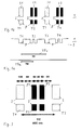
- Figure 1a shows in a cross section a part of an embossed pit structure of an optical storage medium 1 comprising pits P arranged in tracks T1 - T4.
- the optical storage medium 1 is in particular an optical ROM disc.
- the pit structure is made for example by means of a stamper on a substrate layer S in a known manner and comprises a reflective coating, for example an aluminum coating, or a super resolution near-field structure (Super-RENS) layer stack, for providing a high reflectivity for incident laser light of an optical pickup of a corresponding apparatus for reading the digital data.
- a reflective coating for example an aluminum coating
- Super-RENS super resolution near-field structure
- FIG 1b a small part of the optical storage medium 1 of figure 1a is shown in a top view.
- the pits P are arranged along tracks T1 - T4 on the storage medium 1 and represent a mark/space data structure corresponding with digitally coded data.
- the tracks comprise alternatingly partitioned marks and not partitioned marks.
- the first track T1 comprises not partitioned marks 2 and the neighboring second track T2 comprises partitioned marks 3.
- the further tracks T3, T4 are arranged in tracking direction and comprise alternatingly also not partitioned marks 2 and partitioned marks 3.
- the tracks T1 - T4 correspond with two spirals S1, S2, wherein for the first spiral S1 only not partitioned marks 2 are used and for the second spiral S2 partitioned marks 3 are used.
- the spiral S1 with the not partitioned marks 2 corresponds for example in principle with the mark/space data structure of known optical ROM discs, in which also the pits are arranged in a spiral.
- the pits P respectively marks 2 of the track T1 are not partitioned and have different length in accordance with coded digital data.
- the marks of the track T2 are partitioned in two parts in tracking direction and each of the two parts of a mark 3 has in particular the same length along the track.
- the partitioned marks 3 are partitioned advantageously in two equal parts.
- the marks 3 of the track T2 have also different length in accordance with coded digital data, in correspondence with the coding scheme for the marks of the track T1.
- An optical disc in accordance with the optical storage medium 1 as described with regard to figures 1a, 1b comprises in particular a mask layer providing a super resolution near field effect (Super-RENS) for increasing the data density with regard to a Blu-Ray disc.
- Super-RENS super resolution near field effect
- the data density can be increased only in one dimension by using the Super-RENS effect.
- the data density can be increased also in radial direction, by utilizing the different reflectivity factors for the TE polarization component and the TM polarization component of the incident light.
- the incident laser light of a corresponding pickup unit has the polarization direction TM, corresponding with the magnetic field vector pointing in the radial, tracking direction, and the electric field vector pointing in the tangential direction along the track, there is only a small difference in the reflected light between the pits of the track T1 and the partitioned pits of the track T2, because according to this polarization the light penetrates into the holes and is reflected at the bottom of the pits P.
- the pits P of the track T1 have for example a width in radial direction in the range of about 100 nm, and the width of the partitioned marks P of the track T2 is correspondingly smaller, when a pickup unit comprising a blue laser is used for reading of the data.
- the effective phase depth for the pit structure of the track T2 is very different with regard to the pit structure of the track T1, because this polarization direction cannot penetrate into the pits of track T2 and therefore no light is reflected from the bottom of these pits.
- the pit depth of the pits P is advantageously between lambda/8 and lambda/4, which provides both a good HF data and a sufficient push-pull signal for the tracking control of a corresponding optical pickup unit.
- adjacent tracks T1, T2 look different and essentially only the pits of the tracks T1 and T3 contribute to a tracking signal, when the TE polarization component is used for tracking control, because the pits of the track T2 do not provide a relevant signal contribution to the reflected TE polarized light.
- the track width between adjacent tracks T1, T2 is reduced by a factor of 2, in comparison with a Blu-Ray disc, still a push-pull signal can be seen.
- the effective track pitch TPe for the TE polarization component is therefore by a factor of two larger with regard to the track pitch TPm for the TM polarization component, as indicated in figure 1a . Therefore, a track pitch of 400 nm for the TE polarization component can be resolved easily by a pickup unit having a numerical aperture similar to a Blu-Ray pickup.
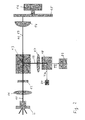
- the apparatus comprises a motor 16 with a turntable, on which an optical disc 15 is placed, and a pickup unit with a laser L.
- the laser L generates a light beam 10, which is collimated by a collimator lens 11 in the direction of an objective lens 14, which provides a beam spot with a very small focus and a high beam intensity on the disc 15.
- the apparatus comprises further a tracking and focusing mechanism, not shown, which moves the pickup unit or the objective lens 14 across the rotating disc 15 for reading of the coded data.
- This mechanism which can be a conventional actuator or a swing arm, performs in particular a tracking movement and a focus movement for keeping the beam spot of the laser L onto one of the tracks of the optical disc 15, for reading the data as contained in a specific track.
- the laser L is for example a blue laser diode providing a wavelength of about 405 nm, and the mechanism comprises mechanical and electrical means, not shown, as known for example from a Blu-Ray disc recorder or reader. Also further means of the apparatus, which are not relevant for the present invention, are omitted for the sake of simplicity, for example the servo system for the motor 16 and signal processing means for obtaining the digital data from the output voltage signal of the pickup unit.
- the pickup unit comprises further a first optical element 12 for providing a beam with a TE polarization and a beam with a TM polarization for the illumination of the disc 15.
- the optical element 12 is for example a half-wave plate, by means of which the intensity of the TE and TM polarized components can be adjusted.
- the optical element 12 is arranged in the beam 10 between the laser L and a non-polarizing beam-splitter 13, which is arranged such that the beam 10 coming form the laser L passes through the beam-splitter 13 essentially unaffected, and the reflected beam 19 coming from the disc 15 is directed to a detection unit, without changing the polarization of the beams 10 and 19.
- the detection unit of the pickup unit comprises a second optical element 18 for separating the TM and TE polarization components, as reflected from the disc 15, a first detector D1 and a second detector D2.
- the second optical element 18 is for example a polarizing beam-splitter, which reflects the TM polarization component under an angle of 90° into the direction of the first detector D1, and which is arranged such that the TE polarization component passes through the polarizing beam-splitter 18 essentially unaffected onto the second detector D2.
- the detection unit comprises advantageously further a focus lens 17 ahead of the second optical element 18, in particular an astigmatic focus lens, for focusing the reflected beam 19 onto the detectors D1, D2.
- the TM polarization component as detected by detector D1 contains the digital data signal of the disc 15, and the TE polarization component received by the detector D2 is used for providing a push-pull tracking signal, as explained before with regard to figures 1a, 1b .
- the detector D2 is for example a four-segment detector with segments A - D, as known.
- the partitioned marks 3, as shown in figures 1a, 1b are dimensioned in particular such that they interact preferably with the TM polarized beam of the pickup unit, but not with the TE polarized beam, and the not partitioned marks 2 are dimensioned such that they interact preferably with the TE polarized beam or with the TM polarized beam and the TE polarized beam the pickup unit.
- the detector D2 can be used also, in a further aspect of the invention, for providing a tracking signal and a data signal.
- the TE polarized beam as received by detector D2 does not see the neighboring partitioned marks 3 of tracks T2 and T4 and therefore no crosstalk from tracks T2, T4 is included in the data signal of the reflected TE polarized beam of the track T3.
- the pickup unit When the pickup unit reads the data of the track T2 comprising partitioned marks 3, the TE polarized beam sees only the neighboring not partitioned marks 2 of tracks T1 and T3 providing a crosstalk signal.
- the TM polarized beam as received by detector D1 sees the data signal of the track T2 and the crosstalk of the tracks T1 and T3. Therefore, by subtracting the crosstalk signal received by detector D2 from the signal of the detector D1 yields a data signal essentially free of crosstalk.
- the track pitch of tracks T1 - T4 of the storage medium 1 can be reduced when using such a pickup unit, even without requiring a mask layer for providing a super resolution near field effect for the storage medium 1.
- the invention is applicable also not only for ROM storage media comprising a pit/land structure, as described with regard to figures 1a, 1b , but can be used also for writable or re-writable storage media comprising for example a data layer with a phase change material.
- the expression "marks" is therefore used in this specification and the claims for describing tracks with a pit/land data structure as well as for describing tracks with a mark/space data structure.
- a first track T1 comprises not partitioned marks 2, respectively pits, having a width of 100 nm.
- a second, neighboring track T2 comprises partitioned marks 3, consisting each of two equal parts P1, P2 having each a width of 50 nm, and which are separated by 30 nm.
- the tracks T1 and T2 are separated by 85 nm.
- the next track T3 corresponds with the first track T1 having again not partitioned marks 2, which track is also separated from the neighboring track T2 by 85 nm.
- the resulting track pitch TPe for such a mark/space data structure as seen by the TE polarization component is therefore 400 nm, which can be easily resolved by a pickup unit as described before with regard to figure 2 , when using a laser with a wavelength of 405 nm.
- An apparatus for reading data from an optical disk with a track structure as described in figure 3 comprises for example a pickup unit with an objective lens and a numerical aperture in correspondence with a Blu-Ray pickup.
- a Blu-Ray pickup the minimum track pitch which can be resolved is about 280 nm, and the standard track pitch of a Blu-Ray disc is 320 nm, to provide a safety margin.
- the reason for this resolution limitation is, that for a push pull signal the 0 th order and the 1 st order beams have to be collected by the objective lens of the pickup for generating an interference signal on the detector segments responsible for the tracking signal.
- a track pitch of 400 nm for the TE polarization component can be resolved therefore easily by a pickup unit having a numerical aperture in correspondence with a Blu-Ray pickup.
- the TM polarization component sees a track pitch of only 200 nm for the track structure of the optical disc of figure 3 , because for reading the data of the tracks T1, T2 a Super-RENS near field effect is utilized, which does not depend on the numerical aperture of the objective lens, and because the TM polarization component is sensitive both to the partitioned marks 2 and to the not partitioned marks 3, as explained before.
- a pit structure utilizing the dimensions as defined for the tracks T1, T2 shown in figure 3 is more complicated to manufacture with regard to not partitioned marks, but it is already compatible with current mastering technology.
- the shortest marks of the track T2 can be made as not partitioned, solid marks because the smallest partitioned marks are the most complicated for mastering. A few not-partitioned marks within a track T2 of predominantly partitioned marks would not have a negative influence for the tracking control of the pickup unit, when reading the data of the tracks T1, T2.
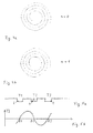
- the data structure for a storage disc as explained with regard to figure 3 may consist of two spirals S1, S2, as explained with regard to figures 1a, 1b , wherein the spiral S1 comprises only not partitioned marks 2 and the spiral S2 comprises only partitioned marks 3.
- a single spiral may be used as shown in figures 4a and 4b .
- the optical disc 1 as shown in figure 4a comprises one spiral S1 which changes always after 360° from partitioned marks to not partitioned marks and vice versa.
- the zero crossing Z2 has to be used.
- the tracking regulation signal TS is inverted. Therefore, only the sign of the signal TS has to be inverted for keeping the pickup unit on the same track.
- the invention is in particular not limited for a use with a pickup unit comprising a Blu-Ray disc type pickup, and is also not only applicable for Super-RENS optical storage media, but can be used also for other optical storage media providing a high data density in tracking direction.
- the invention may be used also for optical storage media comprising concentric tracks, as known from hard disks used in magnetic hard disk drives. The invention resides therefore in the claims herein after appended.
Priority Applications (6)
| Application Number | Priority Date | Filing Date | Title |
|---|---|---|---|
| EP07103729A EP1968048A1 (fr) | 2007-03-08 | 2007-03-08 | Support de stockage optique et appareil de lecture des données respectives |
| TW097105258A TWI447724B (zh) | 2007-03-08 | 2008-02-15 | 軌道具有標記/空間結構之光學儲存媒體及其資料之閱讀裝置 |
| US12/034,909 US8259558B2 (en) | 2007-03-08 | 2008-02-21 | Optical storage medium and apparatus for reading of respective data |
| EP08300107A EP1968050A3 (fr) | 2007-03-08 | 2008-02-22 | Support de stockage optique et appareil de lecture des données respectives |
| CN2008100831315A CN101295517B (zh) | 2007-03-08 | 2008-03-07 | 光学存储介质和用于读取各个数据的装置 |
| JP2008059714A JP5255867B2 (ja) | 2007-03-08 | 2008-03-10 | 光記録媒体とデータ読み出し装置 |
Applications Claiming Priority (1)
| Application Number | Priority Date | Filing Date | Title |
|---|---|---|---|
| EP07103729A EP1968048A1 (fr) | 2007-03-08 | 2007-03-08 | Support de stockage optique et appareil de lecture des données respectives |
Publications (1)
| Publication Number | Publication Date |
|---|---|
| EP1968048A1 true EP1968048A1 (fr) | 2008-09-10 |
Family
ID=38229958
Family Applications (2)
| Application Number | Title | Priority Date | Filing Date |
|---|---|---|---|
| EP07103729A Pending EP1968048A1 (fr) | 2007-03-08 | 2007-03-08 | Support de stockage optique et appareil de lecture des données respectives |
| EP08300107A Withdrawn EP1968050A3 (fr) | 2007-03-08 | 2008-02-22 | Support de stockage optique et appareil de lecture des données respectives |
Family Applications After (1)
| Application Number | Title | Priority Date | Filing Date |
|---|---|---|---|
| EP08300107A Withdrawn EP1968050A3 (fr) | 2007-03-08 | 2008-02-22 | Support de stockage optique et appareil de lecture des données respectives |
Country Status (5)
| Country | Link |
|---|---|
| US (1) | US8259558B2 (fr) |
| EP (2) | EP1968048A1 (fr) |
| JP (1) | JP5255867B2 (fr) |
| CN (1) | CN101295517B (fr) |
| TW (1) | TWI447724B (fr) |
Cited By (3)
| Publication number | Priority date | Publication date | Assignee | Title |
|---|---|---|---|---|
| EP2172934A1 (fr) * | 2008-10-06 | 2010-04-07 | Thomson Licensing | Support de stockage optique comprenant des marques d'orientation différente et appareil correspondant pour la lecture de données |
| EP2246854A1 (fr) * | 2009-04-28 | 2010-11-03 | Thomson Licensing | Support de stockage optique comprenant des codes de modulation différents et appareil correspondant pour la lecture de données |
| US8493832B2 (en) | 2009-04-28 | 2013-07-23 | Thomson Licensing, LLC | Optical storage medium having different dimension of recorded marks and spaces on different tracks |
Families Citing this family (2)
| Publication number | Priority date | Publication date | Assignee | Title |
|---|---|---|---|---|
| JP2012164383A (ja) * | 2011-02-04 | 2012-08-30 | Sony Corp | 光情報記録媒体およびその製造方法 |
| CN111028865B (zh) * | 2019-12-04 | 2022-04-29 | 富通尼激光科技(东莞)有限公司 | 一种在光学信息存储盘上形成机器可读代码的方法 |
Citations (4)
| Publication number | Priority date | Publication date | Assignee | Title |
|---|---|---|---|---|
| EP1107238A1 (fr) * | 1998-08-05 | 2001-06-13 | Seiko Instruments Inc. | Support d'enregistrement, dispositif d'enregistrement d'informations et dispositif de reproduction d'informations |
| WO2003034412A2 (fr) * | 2001-10-19 | 2003-04-24 | Koninklijke Philips Electronics N.V. | Support d'enregistrement optique et dispositif de lecture optique |
| US20040257968A1 (en) * | 2003-06-23 | 2004-12-23 | Samsung Electronics Co., Ltd. | Optical disc with super-resolution near-field structure |
| WO2006056947A1 (fr) * | 2004-11-29 | 2006-06-01 | Koninklijke Philips Electronics N.V. | Support d'enregistrement optique code bidimensionnel comprenant des bits de donnees elliptiques |
Family Cites Families (19)
| Publication number | Priority date | Publication date | Assignee | Title |
|---|---|---|---|---|
| JPS5758248A (en) | 1980-09-24 | 1982-04-07 | Nec Corp | Readout method of high density light beam |
| JPH02123523A (ja) * | 1988-11-02 | 1990-05-11 | Hitachi Ltd | 光学的情報再生装置並びに光学的情報記録媒体並びにカッティング装置および半導体レーザ光源 |
| TW213519B (fr) * | 1991-08-01 | 1993-09-21 | Philips Nv | |
| JPH05182203A (ja) * | 1992-01-07 | 1993-07-23 | Victor Co Of Japan Ltd | 光学的記録媒体円盤 |
| US5982738A (en) * | 1995-02-14 | 1999-11-09 | Hitachi, Ltd. | Optical recording medium having at least wobbled synchronous information shared between tracks |
| JP3159363B2 (ja) * | 1996-02-16 | 2001-04-23 | 日本電気株式会社 | 光再生媒体とその再生方法 |
| JPH11273156A (ja) * | 1998-03-24 | 1999-10-08 | Sanyo Electric Co Ltd | 光ディスク |
| DE60034734T2 (de) * | 1999-04-08 | 2008-01-17 | Pioneer Corporation | Optischer Aufzeichnungsträger |
| JPWO2002039434A1 (ja) * | 2000-11-07 | 2004-03-18 | 松下電器産業株式会社 | 光ディスク、光ディスクの記録装置、光ディスクの再生装置、光ディスクの再生方法及び光ディスクの生産方法 |
| JP2005524192A (ja) * | 2002-05-01 | 2005-08-11 | エルジー エレクトロニクス インコーポレーテッド | 高密度再生専用光ディスクとそれによる光ディスク装置及び方法 |
| KR20050057098A (ko) * | 2002-09-05 | 2005-06-16 | 코닌클리케 필립스 일렉트로닉스 엔.브이. | 2개의 서브그루브를 포함하는 기록형 광 기록매체 |
| US20050281177A1 (en) | 2002-10-04 | 2005-12-22 | Koninklijke Philips Electronics, N.V. | High track density super resolution mo-rom medium |
| JP2004227622A (ja) * | 2003-01-20 | 2004-08-12 | Toshiba Corp | 光記録媒体および光記録再生方法 |
| JP2005243218A (ja) * | 2004-01-30 | 2005-09-08 | Victor Co Of Japan Ltd | 光記録媒体 |
| KR20050086305A (ko) | 2004-02-25 | 2005-08-30 | 삼성전자주식회사 | 초해상 정보 저장매체 및 재생 신호 안정화 방법 |
| JP4289213B2 (ja) * | 2004-05-18 | 2009-07-01 | 日本電気株式会社 | 光ヘッド装置及び光学式情報記録再生装置 |
| JP4412065B2 (ja) * | 2004-06-14 | 2010-02-10 | 日本電気株式会社 | 光ヘッド装置及び光学式情報記録再生装置 |
| JP4393340B2 (ja) * | 2004-10-19 | 2010-01-06 | 三洋電機株式会社 | 光記録媒体、光記録方法、光再生方法、光記録装置および光再生装置。 |
| US20060280091A1 (en) * | 2005-06-13 | 2006-12-14 | Samsung Electronics Co., Ltd. | Information recording medium including a predetermined pattern for detecting and RF signal, a method of determining an optimal recording condition using the predetermined pattern, and a recording and/or reproducing apparatus using the information recording medium |
-
2007
- 2007-03-08 EP EP07103729A patent/EP1968048A1/fr active Pending
-
2008
- 2008-02-15 TW TW097105258A patent/TWI447724B/zh not_active IP Right Cessation
- 2008-02-21 US US12/034,909 patent/US8259558B2/en not_active Expired - Fee Related
- 2008-02-22 EP EP08300107A patent/EP1968050A3/fr not_active Withdrawn
- 2008-03-07 CN CN2008100831315A patent/CN101295517B/zh not_active Expired - Fee Related
- 2008-03-10 JP JP2008059714A patent/JP5255867B2/ja not_active Expired - Fee Related
Patent Citations (4)
| Publication number | Priority date | Publication date | Assignee | Title |
|---|---|---|---|---|
| EP1107238A1 (fr) * | 1998-08-05 | 2001-06-13 | Seiko Instruments Inc. | Support d'enregistrement, dispositif d'enregistrement d'informations et dispositif de reproduction d'informations |
| WO2003034412A2 (fr) * | 2001-10-19 | 2003-04-24 | Koninklijke Philips Electronics N.V. | Support d'enregistrement optique et dispositif de lecture optique |
| US20040257968A1 (en) * | 2003-06-23 | 2004-12-23 | Samsung Electronics Co., Ltd. | Optical disc with super-resolution near-field structure |
| WO2006056947A1 (fr) * | 2004-11-29 | 2006-06-01 | Koninklijke Philips Electronics N.V. | Support d'enregistrement optique code bidimensionnel comprenant des bits de donnees elliptiques |
Cited By (3)
| Publication number | Priority date | Publication date | Assignee | Title |
|---|---|---|---|---|
| EP2172934A1 (fr) * | 2008-10-06 | 2010-04-07 | Thomson Licensing | Support de stockage optique comprenant des marques d'orientation différente et appareil correspondant pour la lecture de données |
| EP2246854A1 (fr) * | 2009-04-28 | 2010-11-03 | Thomson Licensing | Support de stockage optique comprenant des codes de modulation différents et appareil correspondant pour la lecture de données |
| US8493832B2 (en) | 2009-04-28 | 2013-07-23 | Thomson Licensing, LLC | Optical storage medium having different dimension of recorded marks and spaces on different tracks |
Also Published As
| Publication number | Publication date |
|---|---|
| TW200837750A (en) | 2008-09-16 |
| JP2008226436A (ja) | 2008-09-25 |
| US20090028040A1 (en) | 2009-01-29 |
| JP5255867B2 (ja) | 2013-08-07 |
| CN101295517B (zh) | 2013-04-17 |
| TWI447724B (zh) | 2014-08-01 |
| EP1968050A2 (fr) | 2008-09-10 |
| CN101295517A (zh) | 2008-10-29 |
| US8259558B2 (en) | 2012-09-04 |
| EP1968050A3 (fr) | 2009-01-21 |
Similar Documents
| Publication | Publication Date | Title |
|---|---|---|
| US20100027406A1 (en) | Optical storage medium comprising tracks with different width and respective production method | |
| US8259558B2 (en) | Optical storage medium and apparatus for reading of respective data | |
| US20100195476A1 (en) | Optical storage medium comprising tracks with positive and negative marks, and stampers and production methods for manufacturing of the optical storage medium | |
| US8027241B2 (en) | Optical storage medium, mastering method and apparatus for reading of respective data | |
| US7876650B2 (en) | Apparatus comprising a pickup providing three beams for reading data from or writing data to an optical storage medium, and respective optical storage medium | |
| KR20080021052A (ko) | 광학계 | |
| CN101189671A (zh) | 具有3点径向跟踪的光学系统 | |
| JP2005135459A (ja) | 情報記録方法及び情報記録装置 | |
| KR101442007B1 (ko) | 호환성 광 레코딩 매체 | |
| US8213278B2 (en) | System comprising an optical disc and an apparatus for reading of respective data | |
| JP2012226809A (ja) | 光記録媒体及び駆動装置 | |
| US8493832B2 (en) | Optical storage medium having different dimension of recorded marks and spaces on different tracks | |
| JP2004318958A (ja) | 光学ヘッド、記録及び/又は再生装置 | |
| EP2246854A1 (fr) | Support de stockage optique comprenant des codes de modulation différents et appareil correspondant pour la lecture de données | |
| EP2172934A1 (fr) | Support de stockage optique comprenant des marques d'orientation différente et appareil correspondant pour la lecture de données | |
| KR20110047221A (ko) | 호환 가능한 광 기록 매체 |
Legal Events
| Date | Code | Title | Description |
|---|---|---|---|
| PUAI | Public reference made under article 153(3) epc to a published international application that has entered the european phase |
Free format text: ORIGINAL CODE: 0009012 |
|
| AK | Designated contracting states |
Kind code of ref document: A1 Designated state(s): AT BE BG CH CY CZ DE DK EE ES FI FR GB GR HU IE IS IT LI LT LU LV MC MT NL PL PT RO SE SI SK TR |
|
| AX | Request for extension of the european patent |
Extension state: AL BA HR MK RS |
|
| AKX | Designation fees paid | ||
| STAA | Information on the status of an ep patent application or granted ep patent |
Free format text: STATUS: THE APPLICATION IS DEEMED TO BE WITHDRAWN |