EP1966871B1 - Elektrische maschine, insbesondere wechselstrommaschine - Google Patents
Elektrische maschine, insbesondere wechselstrommaschine Download PDFInfo
- Publication number
- EP1966871B1 EP1966871B1 EP06841632.0A EP06841632A EP1966871B1 EP 1966871 B1 EP1966871 B1 EP 1966871B1 EP 06841632 A EP06841632 A EP 06841632A EP 1966871 B1 EP1966871 B1 EP 1966871B1
- Authority
- EP
- European Patent Office
- Prior art keywords
- winding
- phase
- stator
- electrical machine
- machine according
- Prior art date
- Legal status (The legal status is an assumption and is not a legal conclusion. Google has not performed a legal analysis and makes no representation as to the accuracy of the status listed.)
- Not-in-force
Links
Images


Classifications
-
- H—ELECTRICITY
- H02—GENERATION; CONVERSION OR DISTRIBUTION OF ELECTRIC POWER
- H02K—DYNAMO-ELECTRIC MACHINES
- H02K3/00—Details of windings
- H02K3/04—Windings characterised by the conductor shape, form or construction, e.g. with bar conductors
- H02K3/28—Layout of windings or of connections between windings
-
- H—ELECTRICITY
- H02—GENERATION; CONVERSION OR DISTRIBUTION OF ELECTRIC POWER
- H02K—DYNAMO-ELECTRIC MACHINES
- H02K19/00—Synchronous motors or generators
- H02K19/16—Synchronous generators
- H02K19/36—Structural association of synchronous generators with auxiliary electric devices influencing the characteristic of the generator or controlling the generator, e.g. with impedances or switches
Definitions
- the invention relates to an electrical machine, in particular to an alternating current machine having a polyphase stator winding according to the preamble of claim 1.
- the electrical machine according to the invention with the features of claim 1 has the advantage that with the interconnection of a seven-phase stator winding over the known embodiments, a better electromagnetic utilization is achieved, thereby reducing the voltage and torque ripple, the performance curve is raised and the magnetic noise, in particular be largely suppressed in the lower speed range of the machine. Another advantage is to be considered that, especially in high-performance AC machines due to the reduced voltage and torque ripple and the mechanical loads on the machine can be reduced.
- phase strands are the same size, consist of at least one coil and are interconnected with an electrical angle ⁇ between 180 ° / 7 ⁇ 25.7 ° and 180 ° ° * 4 / 7 ⁇ 102.9 °.
- the individual phase strands consist of a plurality of coils, preferably connected in series, for producing the stator winding.
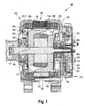
- Fig. 1 is a section through an electric machine in the embodiment shown as an alternator 10 for motor vehicles.
- This has inter alia a two-part housing 33, which consists of a first bearing plate 33.1 and a second bearing plate 33.2.
- the bearing plate 33.1 and the bearing plate 33.2 take in a stand 36, with an annular laminated core 18, in which inwardly open and axially extending grooves 35, a stator winding 11a is inserted.
- the annular stator 36 surrounds with its radially inwardly facing surface an electromagnetically excited rotor 12, which is designed as a claw-pole rotor.
- the rotor 12 is composed, inter alia, of two claw-pole plates 42 and 43, on the outer circumference of which claw-pole fingers 44 and 45 extending in the axial direction are arranged. Both claw pole boards 42 and 43 are arranged in the rotor 12 such that their axially extending claw pole fingers 44, 45 alternate at the periphery of the rotor 12 as north and south poles. This results in magnetically required Klauenpol thoroughlysammlung between the oppositely magnetized Klauenpolfingern 44 and 45, which extend slightly oblique to the machine axis because of tapering to its free ends towards Klauenpolfinger 44 and 45. For the following description of the invention, this course is simplified referred to as axial.
- the rotor 12 is rotatably supported in the respective end shields 33.1 and 33.2 by means of a shaft 47 and one respective rolling bearing 48 located on each side. It has two axial end faces, on each of which a fan 50 is attached. These fans 50 essentially consist of a plate-shaped or disc-shaped section from which fan blades originate in a known manner. These fans 50 serve to allow an air exchange between the outside and the interior of the electric machine 10 via openings 60 in the end shields 33.1 and 33.2. For this purpose, the openings 60 are provided at the axial ends of the end shields 33.1 and 33.2, via which by means of the fan 50 cooling air is sucked into the interior of the electric machine 10.
- This cooling air is accelerated radially outwards by the rotation of the fans 50 so that they can pass through cooling air-permeable winding heads 65 on the drive side and 66 on the electronics side (slip ring, brush or rectifier side). This effect cools the windings.
- the cooling air takes after passing through the winding heads, or after the flow around this winding heads a path radially outward through openings, not shown, between indicated webs.
- a protective cap 67 which protects various components from environmental influences.
- this protective cap 67 covers, for example, a slip ring assembly 69, which supplies a field winding 13 with exciting current.
- this slip ring assembly 69 around a heat sink 73 is arranged, which acts here as a plus heat sink.
- the bearing plate acts 33.2.
- a connection plate 76 is arranged, which fixed in the bearing plate 33.2 minus diodes 78 and in this Representation not shown plus diodes of a rectifier 15 in the heat sink 73 in the form of a bridge circuit interconnects.
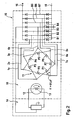
- FIG. 2 shows a schematic representation of an electrical machine according to the invention in the form of a designated 10 alternator for supplying the electrical system of motor vehicles.
- Such generators with a polyphase stator winding 11 are usually equipped with an electrically excited claw pole rotor 12, the field winding 13 is powered by a regulator 14 from the DC output of a rectifier unit 15 and attached together with the controller 14 on the rear bearing plate of the generator, not shown, and with this is permanently connected.
- a more or less wavy DC voltage is delivered to the vehicle electrical system, not shown, in the operation of the generator at the output of the rectifier unit 15, in which the plus and minus terminals 16 of the rectifier Assembly 15 are directly connected to a storage battery of the vehicle.
- the stator winding 11 of the alternator 10 is provided with a total of seven phase strands P1 to P7. All seven phase strands are equal in terms of their coil and number of turns and interconnected with the same electrical angle ⁇ .
- the phase strands P1 to P7 are connected in series with each other in such a way that in the series connection in each case an electrically subsequent phase strand is skipped. This results according to FIG. 2 in that the phase strings P1 to P7 are connected in series in the phase sequence P1-P3-P5-P7-P2-P4-P6.
- phase strands P1 to P7 are interconnected at an electrical angle ⁇ of 180/7 * 3 ° ⁇ 77.1 °.
- the seven phase strands can not be interconnected with the same electrical angle ⁇ with each other large pitch of their stator core.
- an electric machine in particular AC generator for a motor vehicle with a rotor 12 and extending in the axial direction Klauenpolfingern 44, 45 provided, which alternate at the periphery of the rotor 12 as north and south poles, a stator 36, the one Stator core 18 having a arranged in grooves 35 of the stator core 18 stator winding 11, wherein the stator 36 facing the rotor 12, wherein the stator 36 and the rotor 12 is supported by two end shields 33, with an annular coil-shaped field winding 13 which is attached to the rotor 12 is, wherein the stator winding 11 seven winding strands P1, P2, P3, P4, P5, P6, P7, which are connected with an at least approximately equal electrical angle ⁇ in series with each other, wherein in the series connection of the phase strands P1, P2, P3 , P4, P5, P6, P7 in each case at least one adjacent phase strand P1, P2, P3, P4, P5, P6, P7 is skipped.
- the interconnection or series connection of the phase strings P1, P2, P3, P4, P5, P6, P7 is such that the electrically effective Wicklungszug the stator winding 11 and thus the seven phase strands P1, P2, P3, P4, P5, P6, P7 closes after two rounds.
- stator winding 11 has winding heads 65, 66, which are each cooled by an approximately radial cooling air flow, which is caused by at least at one axial end of a claw pole 42, 43 mounted fan 50.
- FIG. 2 It can also be seen that the connections between the phase strings P1 to P7 are led out in each case to one of seven rectifier bridges B1 to B7 of the rectifier unit 15.
- the rectifier bridges B1 to B7 are connected in a conventional manner by means of two diodes to a two-way rectifier unit 15.
- the interconnection of the phase strands P1 to P7 takes place expediently at the rear end winding of the machine, in the region in the known manner, the rectifier assembly 15 is arranged. It is provided that of the connections between the phase strands P1 to P7 in each case only one connection 1a to 7a is guided to one of the seven rectifier bridges B1 to B7.
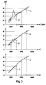
- FIG. 3 turns off the alternator FIG. 2 delivered speed-dependent noise characteristic compared with the noise characteristics of known alternators of the same size.
- the noise characteristic a of an alternator with known three-phase stator winding is shown on the upper axis n1. It shows in the lower speed range between 1500 and 4000 rpm a significantly increased noise, which are based on magnetic noise of the generator and are superimposed on the fan noise.
- FIG. 4 The power characteristics of the generators are shown in a diagram about the speed.
- the dashed line A shows the curve of the output power of an alternator with known three-phase stator winding whose rated power is rated at 100% and which is achieved at a speed n of 6000 rpm.
- the dash-dotted curve B shows the output power of a generator, the stator winding consists in a known manner of seven connected to a heptagon phases.
- the fully extended characteristic C shows the speed-dependent output power of a generator according to the invention with a seven-phase stator winding, according to FIG. 2 is interconnected.
- the inventively designed generator according to its characteristic C already reaches its rated power at about 5000 rpm and in particular can deliver significantly more power in the lower speed range than the known embodiments according to characteristic A and B.
- the power of about 51% according to characteristic curves A and B could be increased to 66% according to characteristic curve C.
- FIG. 5 schematically shows a winding diagram of a seven-phase stator winding 11a, wherein the seven phase strands P1 to P7 are used in the form of a wave winding in the grooves of a stator core, not shown.
- the machine has a two-pole rotor 12a.
- On the right side of the FIG. 4 is indicated by dashed lines that each phase strand P1 to P7 is inserted in several waves in the grooves N1 to N14, so that there is a coil consisting of several turns for each phase phase P1 to P7.
- the beginnings of the phase strands P1 to P7 are denoted by 1a to 7a and the ends by 1e to 7e.
- the winding step of this wave winding 11a is seven grooves.
- the ends 1e to 7e of the winding strands P1 to P7 in each case form the connections to the coil beginning of the subsequently connected in series phase strand. Since, in the series connection of the phase strands P1 to P7, the respectively following electrical coil string is also skipped in order to achieve optimum damping of the magnetic noise and the ripple, the series connection of the coil strands takes place in the same way as in the exemplary embodiment FIG.
- the end 1e of the first winding string P1 is connected to the winding start 3a of the phase string P3, whose end 3e is connected to the beginning 5a of the phase string P5, whose end 5e is connected to the beginning 7a of the phase string P7, whose end 7e becomes the beginning 2a is connected to the beginning 4a of the phase string P4, whose end 4e is connected to the beginning 6a of the phase string P6 and its end 6e is finally connected to the beginning 1a of the first phase string P1. All seven connections are on one and the same side at the rear end winding of the stator winding 11a, wherein the beginnings 1a to 7a of the phase strands P1 to P7 for connecting a rectifier assembly 15 with seven rectifier bridges according to FIG. 2 are led out of the machine.
- FIG. 6 is shown as a further embodiment, the winding diagram of a seven-phase stator winding in the form of a loop winding, which corresponds to a two-pole rotor according to FIG. 5 is also used in 14 grooves N1 to N14 of a stator core.
- the phase strands P1 to P7 are here each formed from two series-connected coils S1 to S14 with a winding step of seven slots.
- the first coil S1 with four turns for example, is placed in the slots N1 and N8, the coil beginning 1a being led out for connecting a rectifier unit 15 to the rear winding head.
- the second coil S2 is placed with four turns in the grooves N8 and N1 and their end 1e also led out to the rectifier unit 15.
- the coils S3 and S4 of the second phase string P2 are then inserted into the stator slots with four turns each, with the coil S3 in the slots N3 and N10 and the coil S4 in the slots N10 and N3.
- the beginning 2a of the coil strand P2 and the end 2e led out at the rear end winding to the rectifier assembly 15. This is repeated in the same way for the respective following phase strands P3 to P7.
- the interconnection of the seven phase phases in the phase sequence according to FIG. 2 takes place here by corresponding, not shown, conductor bridges within the rectifier assembly 15.
- the two series-connected coils S of each winding strand P are wound through with a winding wire 17.
- all seven phase strands P can be wound to achieve the desired series connection with a winding wire 17, in which case according to FIG. 4 the ends 1 to 7e of the winding strands P1 to P7 are laid as connections to the respective beginning 3a to 2a of the next phase phase P on the rectifier winding end of the machine.
- FIG. 7 shows an outbreak of a stator core 18 of the alternator 10 FIG. 2 with the seven-phase stator winding 11.
- the phase strands P1, P5, P2, P6 are each accommodated in adjacent slots N1, N2, N3, N4, each having eight conductors L.
- the phase strands P in each case according to FIG. 6 be made of two series-connected coils with four conductors L or according to FIG. 5 each of a wave winding with eight waves.
- FIG. 8 shows a further Verschaltungsnnenkeit the seven-phase stator winding 11 in which in the series connection of the individual phase strands P1 to P7 each two following phase strands P are skipped.
- the phase strands P in the phase sequence P1-P4-P7-P3-P6-P2-P5 are connected in series via the connections le to 7e.
- the beginnings 1a to 7a of the coil strands P1 to P7 for connecting a rectifier unit 15 according to FIG. 2 led out frontally.
- the phase strands P1 to P7 are connected in series with an electrical angle ⁇ of 180/7 ° ⁇ 25.7 °. This variant is possibly opposite to the execution FIG. 2 less noise and performance optimized.
- the invention is not based on the illustrated and described embodiments Figure 1 to 8 limited. Thus, it may well be appropriate to select an application of the invention of alternators for motor vehicles with a vehicle electrical system voltage of 14V, the number of conductors Z in the grooves N of the stator core 18 greater than 5 and less than 10, if this is necessary for the optimization of machine performance ,
- a preferred application of the invention is in alternators for motor vehicles having four- to eighteen-pole claw-pole rotors and a regulator-controlled excitation current.
- phase strands of the stator winding it may be expedient in high-performance electric machines to use prefabricated conductor bars in the grooves of the stator core and interconnect them on the winding head in a known technique with each other.
- the individual coils of the phase strands P can be connected both in series and in parallel with each other.
- a thick winding wire and two or more parallel winding wires can be wound into phase strands.
Landscapes
- Engineering & Computer Science (AREA)
- Power Engineering (AREA)
- Windings For Motors And Generators (AREA)
- Synchronous Machinery (AREA)
- Control Of Ac Motors In General (AREA)
- Motor Or Generator Cooling System (AREA)
Applications Claiming Priority (2)
| Application Number | Priority Date | Filing Date | Title |
|---|---|---|---|
| DE102005061892A DE102005061892A1 (de) | 2005-12-23 | 2005-12-23 | Elektrische Maschine, insbesondere Drehstrommaschine |
| PCT/EP2006/070225 WO2007074159A1 (de) | 2005-12-23 | 2006-12-27 | Elektrische maschine, insbesondere wechselstrommaschine |
Publications (2)
| Publication Number | Publication Date |
|---|---|
| EP1966871A1 EP1966871A1 (de) | 2008-09-10 |
| EP1966871B1 true EP1966871B1 (de) | 2014-11-05 |
Family
ID=37726709
Family Applications (1)
| Application Number | Title | Priority Date | Filing Date |
|---|---|---|---|
| EP06841632.0A Not-in-force EP1966871B1 (de) | 2005-12-23 | 2006-12-27 | Elektrische maschine, insbesondere wechselstrommaschine |
Country Status (8)
| Country | Link |
|---|---|
| US (1) | US8723386B2 (enExample) |
| EP (1) | EP1966871B1 (enExample) |
| JP (2) | JP5334590B2 (enExample) |
| CN (1) | CN101411038A (enExample) |
| BR (1) | BRPI0620634A2 (enExample) |
| DE (1) | DE102005061892A1 (enExample) |
| ES (1) | ES2525592T3 (enExample) |
| WO (1) | WO2007074159A1 (enExample) |
Families Citing this family (12)
| Publication number | Priority date | Publication date | Assignee | Title |
|---|---|---|---|---|
| FR2918815A1 (fr) * | 2007-07-11 | 2009-01-16 | Valeo Equip Electr Moteur | Stator polyphase pour machine electrique tournante a ventilation interne et machine electrique tournante comportant un tel stator. |
| DE102009055112A1 (de) * | 2008-12-19 | 2010-07-01 | Robert Bosch Gmbh | Elektrische Maschine, insbesondere Wechselstrommaschine |
| EP2312730A1 (en) * | 2009-10-19 | 2011-04-20 | Alstom Technology Ltd | Bushing Arrangement of an Electrical Generator |
| US8941961B2 (en) * | 2013-03-14 | 2015-01-27 | Boulder Wind Power, Inc. | Methods and apparatus for protection in a multi-phase machine |
| DE102014200947A1 (de) * | 2014-01-20 | 2015-08-06 | Wobben Properties Gmbh | Synchrongenerator einer getriebelosen Windenergieanlage |
| DE102014108100A1 (de) * | 2014-06-10 | 2015-12-17 | Dr. Ing. H.C. F. Porsche Aktiengesellschaft | Elektrische Maschine für ein Kraftfahrzeug und Verfahren zum Kühlen einer elektrischen Maschine |
| WO2016006114A1 (ja) * | 2014-07-11 | 2016-01-14 | 日産自動車株式会社 | 燃料電池のインピーダンス測定装置および燃料電池のインピーダンス測定方法 |
| CN105322748B (zh) * | 2014-08-05 | 2017-10-10 | 章昭晖 | 一种七相绕组永磁同步无刷直流电机及其控制方法 |
| DE102016108712A1 (de) | 2016-05-11 | 2017-11-16 | Wobben Properties Gmbh | Synchrongenerator einer getriebelosen Windenergieanlage sowie Verfahren zum Herstellen eines Synchrongenerators und Verwendung von Formspulen |
| US10608565B2 (en) * | 2017-12-07 | 2020-03-31 | General Electric Company | Systems and methods for rotating a crankshaft to start an engine |
| JPWO2020202711A1 (enExample) * | 2019-03-29 | 2020-10-08 | ||
| DE102021129198B3 (de) * | 2021-11-10 | 2023-02-02 | Bayerische Motoren Werke Aktiengesellschaft | Rotor mit verschaltbaren Spuleneinheiten, elektrische Antriebsmaschine sowie Kraftfahrzeug |
Family Cites Families (12)
| Publication number | Priority date | Publication date | Assignee | Title |
|---|---|---|---|---|
| US1974344A (en) * | 1932-12-08 | 1934-09-18 | Harriett Oswald | Induction motor |
| JPS5357415A (en) * | 1976-11-02 | 1978-05-24 | Mitsubishi Electric Corp | Solid commutator motor device |
| DE3345272C2 (de) * | 1983-12-14 | 1986-12-04 | Siemens AG, 1000 Berlin und 8000 München | Verfahren zum Betrieb einer stromrichtergespeisten elektrischen Drehfeldmaschine sowie Ankerwicklung zur Durchführung des Verfahrens |
| JPS60204240A (ja) * | 1984-03-26 | 1985-10-15 | Nippon Denso Co Ltd | 車両用交流発電機 |
| EP0454039B1 (en) * | 1990-04-24 | 1996-10-23 | Nippondenso Co., Ltd. | Alternating current generator having a plurality of independent three-phase windings |
| US6838791B2 (en) * | 2000-11-15 | 2005-01-04 | Borealis Technical Limited | Mesh connected electrical rotating machine with span changing |
| DE10103935A1 (de) * | 2000-02-03 | 2001-08-09 | Denso Corp | Statoranordnung einer elektrischen Umlaufmaschine für ein Fahrzeug |
| US20020125784A1 (en) * | 2001-03-08 | 2002-09-12 | Bramson Eric D. | Reduced magnetic noise and current ripple automotive alternator |
| JP3668938B2 (ja) * | 2001-12-11 | 2005-07-06 | 三菱電機株式会社 | 回転電機 |
| JP3858698B2 (ja) * | 2002-01-11 | 2006-12-20 | 株式会社デンソー | 車両用交流発電機 |
| JP4596820B2 (ja) * | 2004-05-28 | 2010-12-15 | 日立オートモティブシステムズ株式会社 | 車両用交流発電機 |
| JP4425006B2 (ja) * | 2004-01-19 | 2010-03-03 | 三菱電機株式会社 | 車両用回転電機 |
-
2005
- 2005-12-23 DE DE102005061892A patent/DE102005061892A1/de not_active Withdrawn
-
2006
- 2006-12-27 JP JP2008546492A patent/JP5334590B2/ja not_active Expired - Fee Related
- 2006-12-27 CN CNA2006800486386A patent/CN101411038A/zh active Pending
- 2006-12-27 BR BRPI0620634-4A patent/BRPI0620634A2/pt not_active Application Discontinuation
- 2006-12-27 US US12/158,786 patent/US8723386B2/en active Active
- 2006-12-27 WO PCT/EP2006/070225 patent/WO2007074159A1/de not_active Ceased
- 2006-12-27 EP EP06841632.0A patent/EP1966871B1/de not_active Not-in-force
- 2006-12-27 ES ES06841632.0T patent/ES2525592T3/es active Active
-
2012
- 2012-06-18 JP JP2012137359A patent/JP5436622B2/ja not_active Expired - Fee Related
Also Published As
| Publication number | Publication date |
|---|---|
| WO2007074159A1 (de) | 2007-07-05 |
| JP5334590B2 (ja) | 2013-11-06 |
| EP1966871A1 (de) | 2008-09-10 |
| US8723386B2 (en) | 2014-05-13 |
| JP2009521197A (ja) | 2009-05-28 |
| DE102005061892A1 (de) | 2007-06-28 |
| CN101411038A (zh) | 2009-04-15 |
| JP2012200142A (ja) | 2012-10-18 |
| US20090001840A1 (en) | 2009-01-01 |
| ES2525592T3 (es) | 2014-12-26 |
| JP5436622B2 (ja) | 2014-03-05 |
| BRPI0620634A2 (pt) | 2011-11-16 |
Similar Documents
| Publication | Publication Date | Title |
|---|---|---|
| DE60018022T2 (de) | Rotierende elektrische Maschine für Fahrzeuge | |
| DE60025655T2 (de) | Wechselstromgenerator | |
| EP2115858B1 (de) | Mehrphasige elektrische maschine | |
| EP0394527B1 (de) | Heteropolar erregte Synchronmaschine | |
| DE102014003658A1 (de) | Reluktanzmotor | |
| DE4334932A1 (de) | Rotierende elektrische Maschine | |
| WO2007141230A1 (de) | Wechselstromgenerator für kraftfahrzeuge | |
| DE10056558B4 (de) | Wechselstromgenerator zur Verwendung in einem Fahrzeug | |
| EP1966871B1 (de) | Elektrische maschine, insbesondere wechselstrommaschine | |
| DE102004023253A1 (de) | Elektrische Drehmaschine | |
| EP2089953A2 (de) | Elektrische maschine | |
| DE102006008054A1 (de) | Rotierende elektrische Maschine | |
| DE102011114139A1 (de) | Elektromotor, insbesondere polumschaltbarer Motor, Verfahren zum Betreiben eines Elektromotors und Elektromotor | |
| WO2006122985A1 (de) | Fünfphasiger generator | |
| EP1969697B1 (de) | Elektrische Maschine, insbesondere Wechselstromgenerator für ein Kraftfahrzeug | |
| WO2005034308A1 (de) | Ständer für eine elektrische maschine | |
| DE102016118995A1 (de) | Aufbau eines Motor/Generators mit zugehöriger Leistungselektronik für die kontrollierte Versorgung eines Zweispannungsbordnetzes mit Leistung | |
| WO2010070144A2 (de) | Elektrische maschine, insbesondere wechselstrommaschine | |
| WO2009068356A1 (de) | Elektrische maschine | |
| EP2228889B1 (de) | Elektrische Maschine und Verfahren zur Herstellung einer elektrischen Maschine | |
| DE102010001207A1 (de) | Elektrische Maschine zum Starten von Brennkraftmaschinen | |
| DE102008006399A1 (de) | Drehstromzahnspulenwicklung für Asynchronmaschinen | |
| DE102004054862A1 (de) | Flussmodifizierer für permanenterregten Bürstenmotor unter Verwendung von gewickelten Feldspulen in Kombination mit Permanentmagneten | |
| DE102016221416A1 (de) | Elektrische Maschine | |
| DE102004054898A1 (de) | Elektrische Maschine zur Wandlung von elektrischer Energie in mechanische Energie |
Legal Events
| Date | Code | Title | Description |
|---|---|---|---|
| PUAI | Public reference made under article 153(3) epc to a published international application that has entered the european phase |
Free format text: ORIGINAL CODE: 0009012 |
|
| 17P | Request for examination filed |
Effective date: 20080723 |
|
| AK | Designated contracting states |
Kind code of ref document: A1 Designated state(s): DE ES FR GB IT |
|
| DAX | Request for extension of the european patent (deleted) | ||
| RBV | Designated contracting states (corrected) |
Designated state(s): DE ES FR GB IT |
|
| 17Q | First examination report despatched |
Effective date: 20130708 |
|
| GRAP | Despatch of communication of intention to grant a patent |
Free format text: ORIGINAL CODE: EPIDOSNIGR1 |
|
| INTG | Intention to grant announced |
Effective date: 20140610 |
|
| GRAS | Grant fee paid |
Free format text: ORIGINAL CODE: EPIDOSNIGR3 |
|
| GRAA | (expected) grant |
Free format text: ORIGINAL CODE: 0009210 |
|
| AK | Designated contracting states |
Kind code of ref document: B1 Designated state(s): DE ES FR GB IT |
|
| REG | Reference to a national code |
Ref country code: GB Ref legal event code: FG4D Free format text: NOT ENGLISH |
|
| REG | Reference to a national code |
Ref country code: DE Ref legal event code: R096 Ref document number: 502006014062 Country of ref document: DE Effective date: 20141218 |
|
| REG | Reference to a national code |
Ref country code: ES Ref legal event code: FG2A Ref document number: 2525592 Country of ref document: ES Kind code of ref document: T3 Effective date: 20141226 |
|
| REG | Reference to a national code |
Ref country code: DE Ref legal event code: R097 Ref document number: 502006014062 Country of ref document: DE |
|
| PLBE | No opposition filed within time limit |
Free format text: ORIGINAL CODE: 0009261 |
|
| STAA | Information on the status of an ep patent application or granted ep patent |
Free format text: STATUS: NO OPPOSITION FILED WITHIN TIME LIMIT |
|
| 26N | No opposition filed |
Effective date: 20150806 |
|
| GBPC | Gb: european patent ceased through non-payment of renewal fee |
Effective date: 20150205 |
|
| REG | Reference to a national code |
Ref country code: FR Ref legal event code: PLFP Year of fee payment: 10 |
|
| PG25 | Lapsed in a contracting state [announced via postgrant information from national office to epo] |
Ref country code: GB Free format text: LAPSE BECAUSE OF NON-PAYMENT OF DUE FEES Effective date: 20150205 |
|
| REG | Reference to a national code |
Ref country code: FR Ref legal event code: PLFP Year of fee payment: 11 |
|
| REG | Reference to a national code |
Ref country code: DE Ref legal event code: R081 Ref document number: 502006014062 Country of ref document: DE Owner name: SEG AUTOMOTIVE GERMANY GMBH, DE Free format text: FORMER OWNER: ROBERT BOSCH GMBH, 70469 STUTTGART, DE |
|
| REG | Reference to a national code |
Ref country code: FR Ref legal event code: PLFP Year of fee payment: 12 |
|
| REG | Reference to a national code |
Ref country code: ES Ref legal event code: PC2A Owner name: SEG AUTOMOTIVE GERMANY GMBH Effective date: 20180119 |
|
| REG | Reference to a national code |
Ref country code: FR Ref legal event code: TP Owner name: SEG AUTOMOTIVE GERMANY GMBH, DE Effective date: 20180315 |
|
| REG | Reference to a national code |
Ref country code: DE Ref legal event code: R082 Ref document number: 502006014062 Country of ref document: DE Representative=s name: DEHNSGERMANY PARTNERSCHAFT VON PATENTANWAELTEN, DE |
|
| PGFP | Annual fee paid to national office [announced via postgrant information from national office to epo] |
Ref country code: FR Payment date: 20211220 Year of fee payment: 16 Ref country code: DE Payment date: 20211222 Year of fee payment: 16 |
|
| PGFP | Annual fee paid to national office [announced via postgrant information from national office to epo] |
Ref country code: IT Payment date: 20211223 Year of fee payment: 16 |
|
| PGFP | Annual fee paid to national office [announced via postgrant information from national office to epo] |
Ref country code: ES Payment date: 20220105 Year of fee payment: 16 |
|
| REG | Reference to a national code |
Ref country code: DE Ref legal event code: R119 Ref document number: 502006014062 Country of ref document: DE |
|
| PG25 | Lapsed in a contracting state [announced via postgrant information from national office to epo] |
Ref country code: DE Free format text: LAPSE BECAUSE OF NON-PAYMENT OF DUE FEES Effective date: 20230701 |
|
| PG25 | Lapsed in a contracting state [announced via postgrant information from national office to epo] |
Ref country code: FR Free format text: LAPSE BECAUSE OF NON-PAYMENT OF DUE FEES Effective date: 20221231 |
|
| PG25 | Lapsed in a contracting state [announced via postgrant information from national office to epo] |
Ref country code: IT Free format text: LAPSE BECAUSE OF NON-PAYMENT OF DUE FEES Effective date: 20221227 |
|
| REG | Reference to a national code |
Ref country code: ES Ref legal event code: FD2A Effective date: 20240201 |
|
| PG25 | Lapsed in a contracting state [announced via postgrant information from national office to epo] |
Ref country code: ES Free format text: LAPSE BECAUSE OF NON-PAYMENT OF DUE FEES Effective date: 20221228 |
|
| PG25 | Lapsed in a contracting state [announced via postgrant information from national office to epo] |
Ref country code: ES Free format text: LAPSE BECAUSE OF NON-PAYMENT OF DUE FEES Effective date: 20221228 |