EP1963781B1 - Abtastsystem zum abtasten einer objektoberfläche, insbesondere für eine koordinaten-messmaschine - Google Patents
Abtastsystem zum abtasten einer objektoberfläche, insbesondere für eine koordinaten-messmaschine Download PDFInfo
- Publication number
- EP1963781B1 EP1963781B1 EP06829248A EP06829248A EP1963781B1 EP 1963781 B1 EP1963781 B1 EP 1963781B1 EP 06829248 A EP06829248 A EP 06829248A EP 06829248 A EP06829248 A EP 06829248A EP 1963781 B1 EP1963781 B1 EP 1963781B1
- Authority
- EP
- European Patent Office
- Prior art keywords
- light
- transport module
- scanning
- module
- fluid
- Prior art date
- Legal status (The legal status is an assumption and is not a legal conclusion. Google has not performed a legal analysis and makes no representation as to the accuracy of the status listed.)
- Not-in-force
Links
- 238000005259 measurement Methods 0.000 title claims description 11
- 230000033001 locomotion Effects 0.000 claims description 34
- 230000003287 optical effect Effects 0.000 claims description 25
- 239000012530 fluid Substances 0.000 claims description 15
- 238000001514 detection method Methods 0.000 claims description 11
- 238000013519 translation Methods 0.000 claims description 10
- 230000000737 periodic effect Effects 0.000 claims description 2
- 230000002452 interceptive effect Effects 0.000 claims 1
- 238000000034 method Methods 0.000 description 12
- 238000003860 storage Methods 0.000 description 7
- 238000013461 design Methods 0.000 description 4
- 239000013307 optical fiber Substances 0.000 description 3
- 239000000523 sample Substances 0.000 description 3
- 238000005070 sampling Methods 0.000 description 3
- 238000012360 testing method Methods 0.000 description 3
- 230000008859 change Effects 0.000 description 2
- 230000001419 dependent effect Effects 0.000 description 2
- 238000006073 displacement reaction Methods 0.000 description 2
- 230000000694 effects Effects 0.000 description 2
- 238000005516 engineering process Methods 0.000 description 2
- 238000011089 mechanical engineering Methods 0.000 description 2
- 238000000926 separation method Methods 0.000 description 2
- 206010001497 Agitation Diseases 0.000 description 1
- 108010076504 Protein Sorting Signals Proteins 0.000 description 1
- 230000002411 adverse Effects 0.000 description 1
- 230000005540 biological transmission Effects 0.000 description 1
- 239000004020 conductor Substances 0.000 description 1
- 238000010276 construction Methods 0.000 description 1
- 230000008878 coupling Effects 0.000 description 1
- 238000010168 coupling process Methods 0.000 description 1
- 238000005859 coupling reaction Methods 0.000 description 1
- 230000006866 deterioration Effects 0.000 description 1
- 238000010586 diagram Methods 0.000 description 1
- 230000004069 differentiation Effects 0.000 description 1
- 230000005684 electric field Effects 0.000 description 1
- 230000005284 excitation Effects 0.000 description 1
- 230000002349 favourable effect Effects 0.000 description 1
- 239000000835 fiber Substances 0.000 description 1
- 238000007667 floating Methods 0.000 description 1
- 239000003365 glass fiber Substances 0.000 description 1
- 230000010354 integration Effects 0.000 description 1
- 239000007788 liquid Substances 0.000 description 1
- 238000012423 maintenance Methods 0.000 description 1
- 238000004519 manufacturing process Methods 0.000 description 1
- 230000010355 oscillation Effects 0.000 description 1
- 230000008569 process Effects 0.000 description 1
- 238000012545 processing Methods 0.000 description 1
- 230000000750 progressive effect Effects 0.000 description 1
- 238000005096 rolling process Methods 0.000 description 1
- 238000004904 shortening Methods 0.000 description 1
- 230000008054 signal transmission Effects 0.000 description 1
- 210000002023 somite Anatomy 0.000 description 1
- 230000007847 structural defect Effects 0.000 description 1
- 230000003746 surface roughness Effects 0.000 description 1
- 230000001360 synchronised effect Effects 0.000 description 1
- 230000000007 visual effect Effects 0.000 description 1
Images

Classifications
-
- G—PHYSICS
- G01—MEASURING; TESTING
- G01B—MEASURING LENGTH, THICKNESS OR SIMILAR LINEAR DIMENSIONS; MEASURING ANGLES; MEASURING AREAS; MEASURING IRREGULARITIES OF SURFACES OR CONTOURS
- G01B11/00—Measuring arrangements characterised by the use of optical techniques
- G01B11/002—Measuring arrangements characterised by the use of optical techniques for measuring two or more coordinates
- G01B11/005—Measuring arrangements characterised by the use of optical techniques for measuring two or more coordinates coordinate measuring machines
- G01B11/007—Measuring arrangements characterised by the use of optical techniques for measuring two or more coordinates coordinate measuring machines feeler heads therefor
-
- G—PHYSICS
- G01—MEASURING; TESTING
- G01B—MEASURING LENGTH, THICKNESS OR SIMILAR LINEAR DIMENSIONS; MEASURING ANGLES; MEASURING AREAS; MEASURING IRREGULARITIES OF SURFACES OR CONTOURS
- G01B11/00—Measuring arrangements characterised by the use of optical techniques
- G01B11/02—Measuring arrangements characterised by the use of optical techniques for measuring length, width or thickness
- G01B11/03—Measuring arrangements characterised by the use of optical techniques for measuring length, width or thickness by measuring coordinates of points
-
- G—PHYSICS
- G01—MEASURING; TESTING
- G01B—MEASURING LENGTH, THICKNESS OR SIMILAR LINEAR DIMENSIONS; MEASURING ANGLES; MEASURING AREAS; MEASURING IRREGULARITIES OF SURFACES OR CONTOURS
- G01B11/00—Measuring arrangements characterised by the use of optical techniques
- G01B11/24—Measuring arrangements characterised by the use of optical techniques for measuring contours or curvatures
Definitions
- the task is to accurately scan the surface of an object.
- to scan is to be understood in the general sense that it refers to any method in which a plurality of measuring points are obtained on a surface to information about their shape in the To get space. In particular, it is about the determination of the exact dimensions of an object (“dimensional testing"), but also about structural properties of the surface, so for example their roughness.
- the scanning system according to the invention is particularly suitable as a so-called "touch sensor” for coordinate measuring machines, which are used for example in industrial manufacturing plants, but also in laboratories for dimensional testing including the determination of surface structures and structural defects.
- coordinate measuring machines have a multi-dimensional high-precision drive with which a touch sensor is moved relative to the object to be tested, the surface of which is scanned by the touch sensor.
- Another important field of application is position robots.
- buttons are used, which touch the DUT with a thin tip or small ball, which contact is detected by electronic means.
- a very good accuracy of mechanical probe can be achieved down to the sub-micron range, however, the touch is when measuring objects associated with significant disadvantages, because on the one hand, the scanning speed and thus the entire measuring time is high and on the other hand in sensitive or elastic surfaces damage or measurement deviations are inevitable.
- Non-contact scanning sensors are generally based on image processing technology.
- the object to be measured is illuminated with special lighting techniques (dark field, bright field, transmitted light) and observed by means of video technology, the results being evaluated by means of image processing software and converted into the desired dimensional information.
- this technique is only suitable for certain objects and requires large and expensive sensors.
- sensors using optical means for example laser distance sensors especially recommended for rapidly measuring the flatness of a DUT and for measuring low curved free-form surfaces, or fiber optic sensors with very fine glass fibers whose distortion is visual when hitting the surface is observed.
- the invention deals with the technical problem of providing a compact, very accurate, fast and inexpensive to produce scanning system.
- the light emanating from the light source of the optical measuring arrangement used here is used as a primary light, which at the object or a Reference reflector reflected light called secondary light.
- the rotation-translation drive is preferably attached to the bearing part.
- the optical scanning sensor used in the invention with at least one fluid-mounted light transport module allows in a confined space and with a very small moving mass, the integration of the one hand for the light transport (optics) and on the other hand for the scanning (actuator) necessary functional components.
- the invention is fundamentally suitable for different optical measuring methods.
- a confocal measuring arrangement can be used, in which light is emitted and detected in a focused manner by the light transport module, whereby a differentiation in the beam direction (“longitudinal scanning") is achieved by varying the focusing.
- the invention is suitable for sampling by means of a short-coherence interferometer arrangement.
- short-coherence interferometers also known as “white-light interferometers”
- optical-optical Sensing by detecting the position of light-emitting locations located at different distances from the apparatus along a scan-direction (ie, longitudinal-scan) scan path. This method is also referred to as “Low Coherence Distance Scan (LCDS)".
- LCDS Low Coherence Distance Scan
- the interferometer arrangement usually comprises, in addition to the short-coherent light source (at least) a beam splitter, a reference reflector and the detector.
- the light paths between these elements form interferometer arms.
- the primary light passes from the light source through a light source arm to the beam splitter and is split there.
- a first portion of the primary light is irradiated as a measuring light via an object arm in the scanning direction on the object, while a second portion of the primary light passes as a reference light via a reflector arm to the reference reflector.
- Both light components are reflected (the measuring light at light-reflecting sites of the object to be examined, the reference light at the reference reflector) and, after reflection, returned to the beam splitter as secondary light on the same light path (object arm or reference arm).
- the secondary light components are combined and fed to the detector as detection light via a detection arm.
- a subsection of the measuring light path and preferably also a subsection of the reference light path runs within at least one fluid-supported light transport module.
- the longitudinal scan position is varied in rapid succession. This is usually done by changing the relation of the lengths of the reference light path and the Meßlichtweges. This will be the position on the scanning path changed, for which the condition for the interference of the measuring light and the reference light (namely, that differ the optical path length of both light paths at most by the coherence length of the light path from each other) is met.
- the current scanning position is in each case that position on the scanning path for which the optical length of the entire measuring light path coincides with the optical length of the entire reference light path in the respective interferometer arrangement ("coherence condition").
- the reference mirror is displaced in the direction of the reference beam, thereby shortening or lengthening the reference light path.
- WO 03/073041 is particularly concerned with a special LCDS method, which allows an extremely fast longitudinal scanning, which can not be achieved by moving a reference mirror: Also in the context of the present invention, this particular method is preferably used, but are also other prior art interferometer arrangements usable in conjunction with the present invention. Examples are in the DE 19819762 and in the publication citations of the WO 03/073041 described.
- a liquid or a gas is suitable as a fluid for the fluid storage of at least one light transport module according to the invention.
- the storage preferably takes place by means of a gas, in particular air.
- air is based on the fact that the air is forced by means of an external source of compressed air into a bearing gap between the light transport module and the bearing part. It is preferably limited on the one hand by the outer wall of a cylindrical bearing portion of the light transport module and on the other hand by the inner wall of the bearing part, which faces the bearing portion of the light transport module.
- the air pressure must be so Be high that is prevented by the air cushion formed between the bearing surfaces, a contact of the bearing surfaces under the forces occurring during operation of the scanning.
- the scanning sensor includes two light-transporting elements, both of which are fluid-mounted, preferably within a common bearing part.
- the storage is carried out but not necessarily by means of a single bearing gap.
- the invention also includes embodiments in which a second light transport module telescopically penetrates at least partially into a corresponding recess of the first light transport module and there is fluid-stored in a bearing gap between the two light transport modules. In this case, therefore, the fluid storage takes place at least partially not directly between the bearing part and the light transport module, but indirectly via the first light transport module.
- air bearings are primarily used to store shafts that rotate at extremely high speeds; used (see, eg DE 102 10 750 B4 ). In the context of the present invention, it is not about comparably high speeds. Also, the practical freedom from friction of air bearings is not important. Rather, the invention makes use of the property of an air bearing (or other fluid bearing) that it allows by means of the same bearing elements a "real" two-dimensional unrestricted axial mobility and rotation by means of a single bearing. In order to enable these two degrees of freedom of movement by means of roller bearings, separate axial and rotary bearings must be used in practice. A bearing, which also allows a longitudinal displacement in addition to the rotation of a (cylindrical) shaft, is also referred to as a "floating bearing" in mechanical engineering.
- such a bearing is combined with a rotational-translation drive, which can move the fluid-bearing light transport module both in rotation and in the axial direction.
- the rotation-translation drive is firmly connected to the bearing part.
- different drive concepts For example, (non-contact) electromagnetic drives used.
- a drive by means of transport elements which are intermittently pressed in the bearing section against the wall and thereby perform stepwise movements tangentially to the wall surface such that the light transport module is moved in the desired direction.
- a drive in which the transport elements are moved piezoelectrically.
- Piezoelectric drives which are also referred to as "piezomotor” have at least one leg ("Leg"), which consists of a plurality of stacked piezoceramic layers, between each of which is a conductive material. By means of a controlled electric field, the legs can be replaced in synchronous movements, by which a progressive movement of an adjacent surface can be effected. Although the length of the individual steps is typically a few ⁇ m, speeds of several cm / sec can be achieved with frequencies of several 10,000 steps / sec. Piezo motors of this kind are produced, for example, by Piezomotor AB Uppsala AB, Sweden.
- piezoelectric actuators allow a continuous and well controllable rotary motion and are very low maintenance.
- a disadvantage considered that they require a certain contact pressure, because the force required for the movement is transmitted by friction between the transport elements and the object to be moved.
- it has been found that such a drive in combination with the fluid bearing is very well suited for an inventive optical scanning system.
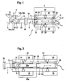
- the in FIG. 1 shown scanning sensor 1 has an elongated light transport module 2, which is air-bearing by means of a bearing part 3.
- the light transport module 2 is surrounded at least in a bearing section 5 by a cylindrical outer wall 6, which in turn is surrounded by the bearing part 3 such that therebetween a bearing gap 7 is present, is pressed into the air from a compressed air source, not shown.
- the design of the bearing section 5 and the bearing part 3 and the pressure of the air pressed into the bearing gap 7 must be matched to one another such that the light transport module 2 is stored without contact within the entire desired range of motion and taking into account the loads occurring during operation.
- the light transport module 2 has one or more cylindrical bearing sections with a relatively short extent in the axial direction, as far as their dimensions are sufficient to ensure the desired axial mobility.
- at least that part length of the light transport module 2, which is at least temporarily within the bearing part 3 during operation of the scanning sensor, is cylindrical.
- the light transport module 2 contains in its interior 8 a consisting of elements of the free-beam optics, in particular lenses 9,10 optical system is transported by the primary light from a light entry point 11 to an axially remote from this light exit point 12, in the present case, two light exit points 12a and 12b are provided, of which the primary light is emitted on the one hand in the axial direction and on the other hand in the radial direction on an object surface 13,14. Secondary light reflected by the object surface 13 or 14 enters the elongated light transport module 2 again at a secondary light entry point 16a, 16b matching the respective light exit point 12a, 12b and becomes a secondary light through the optical system present in its interior space 8 Outlet passage 17 passed, which coincides in the illustrated case with the primary light entry point 11.
- a light exit optics 19 which includes a prism 20 with a preferably wavelength-dependent beam splitter layer 21 in the illustrated case.
- the beam splitter layer 21 Through the beam splitter layer 21, the light in the spatial directions axially (light exit point 12a) and radially (light exit point 12b) divided, on the one hand in the axial direction in front of the light transport module 2 located object surface 13 and on the other hand in the radial direction laterally of the light transport module 2 object surface 14th to be able to feel.
- the scanning sensor 1 simultaneously allows both scanning directions, wherein the light components can be separated in a known manner. In the case shown, the separation takes place by means of the wavelength-dependent beam splitter layer in conjunction with different primary light wavelengths for the radial and axial scanning.
- the light exit optics 19 is not integrally formed (integrally) with the rest of the light transport module 2, but part of a exit optics module 23 which can be interchangeably connected by means of a clutch 24 with a Abtastmodulbasisteil 25, which includes in particular the bearing portion 5 and preferably all contains remaining parts of the light transport module.
- the light transport module 2 can be driven both in the axial direction and in rotation in the bearing part 3 by means of a rotational-translation drive 27, wherein the drive is preferably fastened to the bearing part 3 and acts on the drive rotor 2.
- a drive is preferably used which presses intermittently against the wall 8 thereof by means of transport elements 28 shown symbolically in the bearing section 5, wherein the transport elements 28 perform stepwise movements tangential to the wall surface such that the light transport module 2 in the desired direction is moved.
- the transport elements 28 are preferably moved piezoelectrically by means of a piezo drive electronics 29.
- separate transport elements 28 are provided for the axial movement and for the rotating movement, which perform tangential movements in the corresponding spatial directions (in the axial direction or transversely thereto), if the corresponding axial or rotating movement is desired.
- the axially acting transport elements are preferably in an operating state (for example, the second operating mode explained above), in which the rotational movement is hindered as little as possible.
- the transport elements 28 responsible for the rotation are in an operating state that hinders the axial movement as little as possible.
- the transport elements 28 are arranged distributed on the bearing portion 5 surrounding the bearing part 3 so that the forces exerted by them on the wall 6 cancel each other substantially. In any case, their force effects should compensate such that by the pressure of the transport elements 28, no radial movement of the bearing portion 5 and thus the light transport module 2 is caused, which disturbs the sampling ("compensation condition"). In the simplest case, therefore, the transport elements are arranged in pairs such that they press from opposite circumferential positions, but in the same axial position, against the wall 8 of the bearing portion 5 of the light transport module 2.
- a special feature of the scanning sensor 1 of FIG. 2 compared to FIG. 1 is that it has another fluid-bearing light transport module, referred to as the longitudinal scan module 35. It is precisely coaxial with the light transport module 2 guided so that it is movable in the same axial direction. It includes optical elements, such as lenses 36 and 37, through which the primary light is transported from a primary light entry point 39 through the interior space 38 of the longitudinal scan module 35 to an axially remote primary light exit point 40 of the longitudinal scan module 35 from which it leads Primary light entry point 11 of the first light transport module 2 is forwarded.
- optical elements such as lenses 36 and 37
- secondary light is also transported through the interior 38 of the longitudinal scan module 35, which passes from the primary light exit point 17 of the first light transport module 2 into the interior space 38 via a secondary light entry point 41, which preferably coincides with the primary light exit point 40 of the longitudinal scan module 35, and into it an axially remote secondary light exit point 42 of the longitudinal scanning module 35 is transported, which in turn preferably coincides with the primary light entry point 39.
- the longitudinal scan module 35 is preferably co-located with the first light transport module 2, ie the bearing section of the light transport module 2 and the longitudinal scan module 35 (at least a portion of its length [bearing section]), as in FIG FIG. 2 represented, surrounded by a common bearing part and characterized precise coaxial (in particular in a common cylindrical tube) out.
- FIG. 2 schematically the other necessary components of a preferred optical scanning system are shown, which in addition to the scanning sensor 1 further components of a short-coherence interferometer 45 includes.
- This includes a light source 46, from which primary light is transported via a light source arm 47 realized by means of an optical fiber to a first optical coupler 48. From there, a portion of the primary light passes via a connecting path 50 and a second optical coupler 51 to the primary light entry point 39 of the Lssens shimmerenabtastmoduls 35th
- a peculiarity of the interferometer arrangement shown is that a part of the reference light path designated R1 in a fluid-bearing light transport module (at FIG. 2 in the longitudinal scan module 35 and at FIG. 1 in the light transport module 2). It is the partial distance between the primary light entry point 39 (FIG. FIG. 2 ) or 11 ( FIG. 1 ) and a serving as a reference reflector 53 beam splitter plate which reflects a portion of the light and the remaining part on the Meßlichtweg M1 passes through at least one fluid-bearing light transport module of the scanning sensor 1 to the object surface 13 and 14 respectively.
- the large path length difference between the sections M1 and R1 is compensated by means of a path length compensation module 55, which contains a beam splitter plate 56 and a reflector 57.
- the distance between the beam splitter plate 56 and the reflector 57 is dimensioned such that the optical path length difference between R1 and M1 is compensated by a corresponding optical path length difference between the extending in the Weglynaus GmbHsmodul 55 sections M2 and R2.
- the optical couplers 48 and 51 By means of the optical couplers 48 and 51, the primary light emanating from the light source 46 is coupled into both the scanning sensor 1 and the path length compensation module 55. There are parts of the light to the beam splitter plates 53 and 56 and are reflected there. Other light components arrive in the scanning sensor 1 as far as the surface 13 or 14 to be scanned and are reflected there or pass in the path length compensation module 55 as far as the reflector 57 from which they are reflected. The reflected light travels back as a secondary light, wherein a proportion passes by means of the optical coupler 48 and 51 via a detection path to a detection unit 60.
- the detection unit 60 is designed such that it generates an interference signal only when incident on the one hand reflected by the reference reflector reference light and on the other hand from the surface to be scanned measuring light incident in an interference-capable phase relationship to the detector. Thus, only those light components are evaluated by the detection unit 60, which correspond to the respectively set Longitudinalabtastposition.
- the variation of the scanning position in the context of the invention does not take place by means of a movable reference mirror, but with a stationary reference mirror in combination with one according to the WO 03/073041 formed detection unit 60, which comprises a wavelength selection device 61 shown here only symbolically.
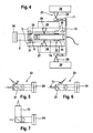
- FIG. 3 shows a further embodiment of a scanning sensor with two fluid-bearing light transport modules, namely a light transport module 2 and a Lssensabtysmodul 35.
- a scanning sensor with two fluid-bearing light transport modules, namely a light transport module 2 and a Lssensabtysmodul 35.
- the Longitudinalabtastmodul 35 with a dip portion 35a penetrates into a corresponding recess of the first light transport module 2. This allows a more favorable positioning of the adjacent optical elements (lenses) 37 and 9, respectively, of the two fluid-supported light transport modules 2, 35. This enables a more effective signal transmission.
- the longitudinal scan module 35 is connected via a flange 70 to drive elements 71 which extend forward from the flange 70 (ie towards the light exit optics).
- the transport elements 28 act on the drive elements 71 by means of a piezo drive electronics 29. This is advantageous if - as shown here - the longitudinal scan module 35 penetrates so far into the light transport module 2 that no sufficient part length of its outer wall is more accessible to the transport elements 28 of the piezo drive.
- FIG. 4 Another peculiarity of in FIG. 4 in that the longitudinal scanning module 35 is mounted in a bearing gap 74 which is formed between its outer wall and the corresponding inner wall of the recess of the first light transport module 2, into which the longitudinal scan module 35 telescopes.
- the Longitudinalabtastmodul 35 is thus not directly, but indirectly stored (via the light transport module 2) within the bearing part 3.
- rotation of the longitudinal scan module 35 is prevented by the driving members 71. It is therefore stored rotationally fixed. Therefore, in the embodiment according to FIG. 4 No rotation position sensor required to control the rotational position of the longitudinal scan module 35.
- the light transport modules are both axially and rotationally movable due to their fluid storage, this possibility does not have to be used in every application. Rather, the invention also extends to scanning systems in which one of the degrees of freedom of movement is not required and therefore the first light transport module (carrying the light exit optics) is moved either only axially or only rotationally. In these cases too, however, there is a translation-rotation drive which controls the movement with respect to both Degrees of freedom and it is preferably also position sensors for precise control of the axial and rotational position available.
- bearing part 3 can be composed of several individual parts, for example two half-shells.
Landscapes
- Physics & Mathematics (AREA)
- General Physics & Mathematics (AREA)
- Length Measuring Devices By Optical Means (AREA)
- Laminated Bodies (AREA)
- Moulds For Moulding Plastics Or The Like (AREA)
- Physical Vapour Deposition (AREA)
- Investigating Or Analysing Materials By Optical Means (AREA)
Applications Claiming Priority (2)
| Application Number | Priority Date | Filing Date | Title |
|---|---|---|---|
| DE102005062130A DE102005062130A1 (de) | 2005-12-23 | 2005-12-23 | Abtastsystem zum Abtasten einer Objektoberfläche, insbesondere für eine Koordinaten-Meßmaschine |
| PCT/EP2006/011586 WO2007079837A1 (de) | 2005-12-23 | 2006-12-02 | Abtastsystem zum abtasten einer objektoberfläche, insbesondere für eine koordinaten-messmaschine |
Publications (2)
| Publication Number | Publication Date |
|---|---|
| EP1963781A1 EP1963781A1 (de) | 2008-09-03 |
| EP1963781B1 true EP1963781B1 (de) | 2010-06-23 |
Family
ID=37697847
Family Applications (1)
| Application Number | Title | Priority Date | Filing Date |
|---|---|---|---|
| EP06829248A Not-in-force EP1963781B1 (de) | 2005-12-23 | 2006-12-02 | Abtastsystem zum abtasten einer objektoberfläche, insbesondere für eine koordinaten-messmaschine |
Country Status (8)
| Country | Link |
|---|---|
| US (1) | US20100220369A1 (enExample) |
| EP (1) | EP1963781B1 (enExample) |
| JP (1) | JP2009520955A (enExample) |
| AT (1) | ATE472089T1 (enExample) |
| AU (1) | AU2006334831A1 (enExample) |
| CA (1) | CA2634290A1 (enExample) |
| DE (2) | DE102005062130A1 (enExample) |
| WO (1) | WO2007079837A1 (enExample) |
Cited By (2)
| Publication number | Priority date | Publication date | Assignee | Title |
|---|---|---|---|---|
| US9494413B2 (en) | 2014-07-23 | 2016-11-15 | Tesa Sa | Probe holder for measuring system |
| US10054434B2 (en) | 2013-04-26 | 2018-08-21 | General Electric Company | Surface roughness measurement device |
Families Citing this family (7)
| Publication number | Priority date | Publication date | Assignee | Title |
|---|---|---|---|---|
| DE502007001288D1 (de) | 2007-01-02 | 2009-09-24 | Isis Sentronics Gmbh | Positionserkennungssystem zur berührungslosen interferometrischen Detektion der Ortsposition eines Zielobjektes und damit ausgestattetes Abtastsystem |
| DE102007008361B3 (de) | 2007-02-16 | 2008-04-03 | Isis Sentronics Gmbh | Abtastsensorsystem zum berührungslosen optischen Abtasten von Objektoberflächen |
| FR2979143B1 (fr) | 2011-08-16 | 2016-03-25 | Univ Joseph Fourier | Dispositif optique d'analyse interferometrique de l'etat de surface interne d'un tube |
| ES2747305T3 (es) * | 2015-10-14 | 2020-03-10 | Sturm Maschinen & Anlagenbau Gmbh | Dispositivo sensor y procedimiento para la inspección de la superficie de un receptáculo hueco cilíndrico |
| KR102499831B1 (ko) * | 2016-05-23 | 2023-02-14 | 코닝 인코포레이티드 | 글라스 시트의 무중력 형상 예측 방법 및 무중력 형상 기반 글라스 시트 품질 관리 방법 |
| CN114434442B (zh) * | 2022-01-21 | 2024-06-25 | 新拓三维技术(深圳)有限公司 | 一种基于协作机器人的自动化检测方法及系统 |
| CN115265359B (zh) * | 2022-06-23 | 2024-07-30 | 宿州捷创模具有限公司 | 汽车钣金验收检具 |
Family Cites Families (14)
| Publication number | Priority date | Publication date | Assignee | Title |
|---|---|---|---|---|
| US4585379A (en) * | 1980-12-27 | 1986-04-29 | Hitachi, Ltd. | Precision positioning device |
| US4928030A (en) * | 1988-09-30 | 1990-05-22 | Rockwell International Corporation | Piezoelectric actuator |
| JPH07167620A (ja) * | 1993-12-13 | 1995-07-04 | Nikon Corp | レーザ測定方法および測定針 |
| DE19640495C2 (de) * | 1996-10-01 | 1999-12-16 | Leica Microsystems | Vorrichtung zur konfokalen Oberflächenvermessung |
| DE19819762A1 (de) * | 1998-05-04 | 1999-11-25 | Bosch Gmbh Robert | Interferometrische Meßeinrichtung |
| DE60033272T2 (de) * | 1999-03-03 | 2007-11-29 | Riken, Wako | Sondenartiger formmessaufnehmer sowie nc-bearbeitungsvorrichtung und formmessverfahren unter verwendung des messaufnehmers |
| JP4262355B2 (ja) * | 1999-05-14 | 2009-05-13 | オリンパス株式会社 | 光イメージング装置 |
| US6687010B1 (en) * | 1999-09-09 | 2004-02-03 | Olympus Corporation | Rapid depth scanning optical imaging device |
| JP2001083077A (ja) * | 1999-09-09 | 2001-03-30 | Olympus Optical Co Ltd | 光イメージング装置 |
| DE19961684A1 (de) * | 1999-12-21 | 2001-06-28 | Philips Corp Intellectual Pty | Aktuator mit einer Kugel und piezo-elektrischen Antrieben |
| DE10207186C1 (de) * | 2002-02-21 | 2003-04-17 | Alexander Knuettel | Niederkohärenz-interferometrisches Gerät zur lichtoptischen Abtastung eines Objektes |
| DE10210750B4 (de) * | 2002-03-12 | 2004-02-12 | Precise Präzisionsspindeln GmbH | Schnellfrequenzspindel |
| JP3908226B2 (ja) * | 2004-02-04 | 2007-04-25 | 日本電産株式会社 | スキャニング型レンジセンサ |
| DE102004012426A1 (de) * | 2004-03-13 | 2005-09-29 | Knüttel, Alexander, Dr. | Niederkohärenz-interferometrisches Verfahren und Gerät zur lichtoptischen Abtastung von Oberflächen |
-
2005
- 2005-12-23 DE DE102005062130A patent/DE102005062130A1/de not_active Withdrawn
-
2006
- 2006-12-02 JP JP2008546175A patent/JP2009520955A/ja active Pending
- 2006-12-02 US US12/086,527 patent/US20100220369A1/en not_active Abandoned
- 2006-12-02 CA CA002634290A patent/CA2634290A1/en not_active Abandoned
- 2006-12-02 EP EP06829248A patent/EP1963781B1/de not_active Not-in-force
- 2006-12-02 WO PCT/EP2006/011586 patent/WO2007079837A1/de not_active Ceased
- 2006-12-02 AU AU2006334831A patent/AU2006334831A1/en not_active Abandoned
- 2006-12-02 DE DE502006007290T patent/DE502006007290D1/de active Active
- 2006-12-02 AT AT06829248T patent/ATE472089T1/de active
Cited By (2)
| Publication number | Priority date | Publication date | Assignee | Title |
|---|---|---|---|---|
| US10054434B2 (en) | 2013-04-26 | 2018-08-21 | General Electric Company | Surface roughness measurement device |
| US9494413B2 (en) | 2014-07-23 | 2016-11-15 | Tesa Sa | Probe holder for measuring system |
Also Published As
| Publication number | Publication date |
|---|---|
| US20100220369A1 (en) | 2010-09-02 |
| DE502006007290D1 (de) | 2010-08-05 |
| EP1963781A1 (de) | 2008-09-03 |
| CA2634290A1 (en) | 2007-07-19 |
| ATE472089T1 (de) | 2010-07-15 |
| JP2009520955A (ja) | 2009-05-28 |
| AU2006334831A1 (en) | 2007-07-19 |
| WO2007079837A1 (de) | 2007-07-19 |
| DE102005062130A1 (de) | 2007-06-28 |
Similar Documents
| Publication | Publication Date | Title |
|---|---|---|
| DE102012104008B3 (de) | Vorrichtung und Verfahren zum Messen von Form-, Lage- und Dimensionsmerkmalen an Maschinenelementen | |
| DE102014113283B4 (de) | Vorrichtung zur Remote-Laserbearbeitung mit Sensor-Scannereinrichtung | |
| DE102013008269B4 (de) | Bearbeitungskopf für eine Laserbearbeitungsvorrichtung und Verfahren zur Laserbearbeitung eines Werkstücks | |
| EP1794540B1 (de) | Optische messvorrichtung zur vermessung von mehreren flächen eines messobjektes | |
| DE112005000639B4 (de) | Vorrichtung und Verfahren zur kombinierten interferometrischen und abbildungsbasierten Geometrieerfassung, insbesondere in der Mikrosystemtechnik | |
| DE102017128158A1 (de) | Abstandsmessungsvorrichtung und Verfahren zur Messung von Abständen | |
| WO2014076649A1 (de) | Optische messverfahren und messvorrichtung mit einem messkopf zum erfassen einer oberflachentopographie mittels kalibrierung der orientierung des messkopfs | |
| DE102008060621B3 (de) | Optische Anordnung zum berührungslosen Messen oder Prüfen einer Körperoberfläche | |
| EP0618439A1 (de) | Bildgebender optischer Aufbau zur Untersuchung stark streuenden Medien | |
| EP2646770A1 (de) | Vorrichtung zur nicht-inkrementellen postions- und formvermessung bewegter festkörper | |
| DE202016006669U1 (de) | Optischer Sensor mit variierbaren Messkanälen | |
| EP3608625B1 (de) | Oct vermessung | |
| EP2592462A1 (de) | Verfahren und Anordnung zur Autofokussierung eines Mikroskops | |
| DE102015221599A1 (de) | Werkzeugmaschine | |
| EP1963781B1 (de) | Abtastsystem zum abtasten einer objektoberfläche, insbesondere für eine koordinaten-messmaschine | |
| DE112021001665T5 (de) | Messvorrichtung für Innenflächenformen und Justierverfahren und Kalibrierverfahren für Messvorrichtung für Innenflächenformen | |
| EP2002204B1 (de) | Verfahren und vorrichtung zur bestimmung und vermessung von formabweichungen und welligkeiten an rotationssymmetrischen teilen | |
| EP2447664A1 (de) | Vorrichtung zum Erfassen von Messinformationen von einer inneren Oberfläche eines Hohlkörpers, insbesondere einer Bohrung eines ein- oder zweiwelligen Extruderzylinders | |
| EP1728045A1 (de) | Niederkohärenz-interferometrisches verfahren und gerät zur lichtoptischen abtastung von oberflächen | |
| EP3435032A1 (de) | Optischer rauheitssensor für eine koordinatenmessmaschine | |
| DE10138656B4 (de) | Oberflächenprofilmesseinrichtung | |
| EP1532422B1 (de) | Tasteinrichtung für vielfältige messaufgaben | |
| EP0573950B1 (de) | Vorrichtung zur winkelauflösenden optischen Untersuchung einer Probe | |
| WO2015011201A1 (de) | Vorrichtung und verfahren zur aufnahme und auswertung von mikroskopischen und/oder speckle-bildern von proben oder oberflächen einer probenebene mit einem auflichtaufbau sowie deren verwendung | |
| DE102006060584B4 (de) | Verfahren und Vorrichtung zur Messung von Verschiebungen und/oder einer Geometrie von Mikrostrukturen |
Legal Events
| Date | Code | Title | Description |
|---|---|---|---|
| PUAI | Public reference made under article 153(3) epc to a published international application that has entered the european phase |
Free format text: ORIGINAL CODE: 0009012 |
|
| 17P | Request for examination filed |
Effective date: 20080614 |
|
| AK | Designated contracting states |
Kind code of ref document: A1 Designated state(s): AT BE BG CH CY CZ DE DK EE ES FI FR GB GR HU IE IS IT LI LT LU LV MC NL PL PT RO SE SI SK TR |
|
| 17Q | First examination report despatched |
Effective date: 20081216 |
|
| GRAP | Despatch of communication of intention to grant a patent |
Free format text: ORIGINAL CODE: EPIDOSNIGR1 |
|
| GRAS | Grant fee paid |
Free format text: ORIGINAL CODE: EPIDOSNIGR3 |
|
| GRAA | (expected) grant |
Free format text: ORIGINAL CODE: 0009210 |
|
| AK | Designated contracting states |
Kind code of ref document: B1 Designated state(s): AT BE BG CH CY CZ DE DK EE ES FI FR GB GR HU IE IS IT LI LT LU LV MC NL PL PT RO SE SI SK TR |
|
| REG | Reference to a national code |
Ref country code: CH Ref legal event code: EP |
|
| REG | Reference to a national code |
Ref country code: IE Ref legal event code: FG4D Free format text: LANGUAGE OF EP DOCUMENT: GERMAN |
|
| REG | Reference to a national code |
Ref country code: CH Ref legal event code: NV Representative=s name: ISLER & PEDRAZZINI AG |
|
| REF | Corresponds to: |
Ref document number: 502006007290 Country of ref document: DE Date of ref document: 20100805 Kind code of ref document: P |
|
| REG | Reference to a national code |
Ref country code: NL Ref legal event code: VDEP Effective date: 20100623 |
|
| PG25 | Lapsed in a contracting state [announced via postgrant information from national office to epo] |
Ref country code: LT Free format text: LAPSE BECAUSE OF FAILURE TO SUBMIT A TRANSLATION OF THE DESCRIPTION OR TO PAY THE FEE WITHIN THE PRESCRIBED TIME-LIMIT Effective date: 20100623 Ref country code: SE Free format text: LAPSE BECAUSE OF FAILURE TO SUBMIT A TRANSLATION OF THE DESCRIPTION OR TO PAY THE FEE WITHIN THE PRESCRIBED TIME-LIMIT Effective date: 20100623 |
|
| LTIE | Lt: invalidation of european patent or patent extension |
Effective date: 20100623 |
|
| PG25 | Lapsed in a contracting state [announced via postgrant information from national office to epo] |
Ref country code: SI Free format text: LAPSE BECAUSE OF FAILURE TO SUBMIT A TRANSLATION OF THE DESCRIPTION OR TO PAY THE FEE WITHIN THE PRESCRIBED TIME-LIMIT Effective date: 20100623 Ref country code: FI Free format text: LAPSE BECAUSE OF FAILURE TO SUBMIT A TRANSLATION OF THE DESCRIPTION OR TO PAY THE FEE WITHIN THE PRESCRIBED TIME-LIMIT Effective date: 20100623 Ref country code: LV Free format text: LAPSE BECAUSE OF FAILURE TO SUBMIT A TRANSLATION OF THE DESCRIPTION OR TO PAY THE FEE WITHIN THE PRESCRIBED TIME-LIMIT Effective date: 20100623 |
|
| PG25 | Lapsed in a contracting state [announced via postgrant information from national office to epo] |
Ref country code: PL Free format text: LAPSE BECAUSE OF FAILURE TO SUBMIT A TRANSLATION OF THE DESCRIPTION OR TO PAY THE FEE WITHIN THE PRESCRIBED TIME-LIMIT Effective date: 20100623 |
|
| PG25 | Lapsed in a contracting state [announced via postgrant information from national office to epo] |
Ref country code: EE Free format text: LAPSE BECAUSE OF FAILURE TO SUBMIT A TRANSLATION OF THE DESCRIPTION OR TO PAY THE FEE WITHIN THE PRESCRIBED TIME-LIMIT Effective date: 20100623 Ref country code: NL Free format text: LAPSE BECAUSE OF FAILURE TO SUBMIT A TRANSLATION OF THE DESCRIPTION OR TO PAY THE FEE WITHIN THE PRESCRIBED TIME-LIMIT Effective date: 20100623 Ref country code: GR Free format text: LAPSE BECAUSE OF FAILURE TO SUBMIT A TRANSLATION OF THE DESCRIPTION OR TO PAY THE FEE WITHIN THE PRESCRIBED TIME-LIMIT Effective date: 20100924 |
|
| REG | Reference to a national code |
Ref country code: IE Ref legal event code: FD4D |
|
| PG25 | Lapsed in a contracting state [announced via postgrant information from national office to epo] |
Ref country code: PT Free format text: LAPSE BECAUSE OF FAILURE TO SUBMIT A TRANSLATION OF THE DESCRIPTION OR TO PAY THE FEE WITHIN THE PRESCRIBED TIME-LIMIT Effective date: 20101025 Ref country code: RO Free format text: LAPSE BECAUSE OF FAILURE TO SUBMIT A TRANSLATION OF THE DESCRIPTION OR TO PAY THE FEE WITHIN THE PRESCRIBED TIME-LIMIT Effective date: 20100623 Ref country code: CY Free format text: LAPSE BECAUSE OF FAILURE TO SUBMIT A TRANSLATION OF THE DESCRIPTION OR TO PAY THE FEE WITHIN THE PRESCRIBED TIME-LIMIT Effective date: 20100623 Ref country code: IS Free format text: LAPSE BECAUSE OF FAILURE TO SUBMIT A TRANSLATION OF THE DESCRIPTION OR TO PAY THE FEE WITHIN THE PRESCRIBED TIME-LIMIT Effective date: 20101023 Ref country code: SK Free format text: LAPSE BECAUSE OF FAILURE TO SUBMIT A TRANSLATION OF THE DESCRIPTION OR TO PAY THE FEE WITHIN THE PRESCRIBED TIME-LIMIT Effective date: 20100623 Ref country code: CZ Free format text: LAPSE BECAUSE OF FAILURE TO SUBMIT A TRANSLATION OF THE DESCRIPTION OR TO PAY THE FEE WITHIN THE PRESCRIBED TIME-LIMIT Effective date: 20100623 |
|
| PGFP | Annual fee paid to national office [announced via postgrant information from national office to epo] |
Ref country code: CH Payment date: 20101223 Year of fee payment: 5 |
|
| PG25 | Lapsed in a contracting state [announced via postgrant information from national office to epo] |
Ref country code: IT Free format text: LAPSE BECAUSE OF FAILURE TO SUBMIT A TRANSLATION OF THE DESCRIPTION OR TO PAY THE FEE WITHIN THE PRESCRIBED TIME-LIMIT Effective date: 20100623 |
|
| PG25 | Lapsed in a contracting state [announced via postgrant information from national office to epo] |
Ref country code: DK Free format text: LAPSE BECAUSE OF FAILURE TO SUBMIT A TRANSLATION OF THE DESCRIPTION OR TO PAY THE FEE WITHIN THE PRESCRIBED TIME-LIMIT Effective date: 20100623 Ref country code: IE Free format text: LAPSE BECAUSE OF FAILURE TO SUBMIT A TRANSLATION OF THE DESCRIPTION OR TO PAY THE FEE WITHIN THE PRESCRIBED TIME-LIMIT Effective date: 20100623 |
|
| PLBE | No opposition filed within time limit |
Free format text: ORIGINAL CODE: 0009261 |
|
| STAA | Information on the status of an ep patent application or granted ep patent |
Free format text: STATUS: NO OPPOSITION FILED WITHIN TIME LIMIT |
|
| 26N | No opposition filed |
Effective date: 20110324 |
|
| BERE | Be: lapsed |
Owner name: ISIS SENTRONICS G.M.B.H. Effective date: 20101231 |
|
| REG | Reference to a national code |
Ref country code: DE Ref legal event code: R097 Ref document number: 502006007290 Country of ref document: DE Effective date: 20110323 |
|
| PG25 | Lapsed in a contracting state [announced via postgrant information from national office to epo] |
Ref country code: MC Free format text: LAPSE BECAUSE OF NON-PAYMENT OF DUE FEES Effective date: 20101231 |
|
| GBPC | Gb: european patent ceased through non-payment of renewal fee |
Effective date: 20101202 |
|
| REG | Reference to a national code |
Ref country code: FR Ref legal event code: ST Effective date: 20110831 |
|
| PG25 | Lapsed in a contracting state [announced via postgrant information from national office to epo] |
Ref country code: BE Free format text: LAPSE BECAUSE OF NON-PAYMENT OF DUE FEES Effective date: 20101231 |
|
| PG25 | Lapsed in a contracting state [announced via postgrant information from national office to epo] |
Ref country code: FR Free format text: LAPSE BECAUSE OF NON-PAYMENT OF DUE FEES Effective date: 20110103 |
|
| PG25 | Lapsed in a contracting state [announced via postgrant information from national office to epo] |
Ref country code: GB Free format text: LAPSE BECAUSE OF NON-PAYMENT OF DUE FEES Effective date: 20101202 |
|
| PGFP | Annual fee paid to national office [announced via postgrant information from national office to epo] |
Ref country code: DE Payment date: 20120222 Year of fee payment: 6 |
|
| REG | Reference to a national code |
Ref country code: CH Ref legal event code: PL |
|
| PG25 | Lapsed in a contracting state [announced via postgrant information from national office to epo] |
Ref country code: HU Free format text: LAPSE BECAUSE OF FAILURE TO SUBMIT A TRANSLATION OF THE DESCRIPTION OR TO PAY THE FEE WITHIN THE PRESCRIBED TIME-LIMIT Effective date: 20101224 Ref country code: LU Free format text: LAPSE BECAUSE OF NON-PAYMENT OF DUE FEES Effective date: 20101202 Ref country code: BG Free format text: LAPSE BECAUSE OF FAILURE TO SUBMIT A TRANSLATION OF THE DESCRIPTION OR TO PAY THE FEE WITHIN THE PRESCRIBED TIME-LIMIT Effective date: 20100623 |
|
| PG25 | Lapsed in a contracting state [announced via postgrant information from national office to epo] |
Ref country code: TR Free format text: LAPSE BECAUSE OF FAILURE TO SUBMIT A TRANSLATION OF THE DESCRIPTION OR TO PAY THE FEE WITHIN THE PRESCRIBED TIME-LIMIT Effective date: 20100623 Ref country code: LI Free format text: LAPSE BECAUSE OF NON-PAYMENT OF DUE FEES Effective date: 20111231 Ref country code: CH Free format text: LAPSE BECAUSE OF NON-PAYMENT OF DUE FEES Effective date: 20111231 |
|
| REG | Reference to a national code |
Ref country code: AT Ref legal event code: MM01 Ref document number: 472089 Country of ref document: AT Kind code of ref document: T Effective date: 20111202 |
|
| PG25 | Lapsed in a contracting state [announced via postgrant information from national office to epo] |
Ref country code: AT Free format text: LAPSE BECAUSE OF NON-PAYMENT OF DUE FEES Effective date: 20111202 |
|
| PG25 | Lapsed in a contracting state [announced via postgrant information from national office to epo] |
Ref country code: BG Free format text: LAPSE BECAUSE OF FAILURE TO SUBMIT A TRANSLATION OF THE DESCRIPTION OR TO PAY THE FEE WITHIN THE PRESCRIBED TIME-LIMIT Effective date: 20100923 |
|
| PG25 | Lapsed in a contracting state [announced via postgrant information from national office to epo] |
Ref country code: ES Free format text: LAPSE BECAUSE OF FAILURE TO SUBMIT A TRANSLATION OF THE DESCRIPTION OR TO PAY THE FEE WITHIN THE PRESCRIBED TIME-LIMIT Effective date: 20101004 Ref country code: DE Free format text: LAPSE BECAUSE OF NON-PAYMENT OF DUE FEES Effective date: 20130702 |
|
| REG | Reference to a national code |
Ref country code: DE Ref legal event code: R119 Ref document number: 502006007290 Country of ref document: DE Effective date: 20130702 |