EP1961911A2 - Gurtführung für ein Gurtband oder dergleichen Zugelement einer Verdunkelungsvorrichtung, insbesondere eines Rollladens, zur Befestigung an Rollladenkästen - Google Patents
Gurtführung für ein Gurtband oder dergleichen Zugelement einer Verdunkelungsvorrichtung, insbesondere eines Rollladens, zur Befestigung an Rollladenkästen Download PDFInfo
- Publication number
- EP1961911A2 EP1961911A2 EP08002595A EP08002595A EP1961911A2 EP 1961911 A2 EP1961911 A2 EP 1961911A2 EP 08002595 A EP08002595 A EP 08002595A EP 08002595 A EP08002595 A EP 08002595A EP 1961911 A2 EP1961911 A2 EP 1961911A2
- Authority
- EP
- European Patent Office
- Prior art keywords
- belt guide
- web
- webbing
- belt
- lateral
- Prior art date
- Legal status (The legal status is an assumption and is not a legal conclusion. Google has not performed a legal analysis and makes no representation as to the accuracy of the status listed.)
- Granted
Links
Images

Classifications
-
- E—FIXED CONSTRUCTIONS
- E06—DOORS, WINDOWS, SHUTTERS, OR ROLLER BLINDS IN GENERAL; LADDERS
- E06B—FIXED OR MOVABLE CLOSURES FOR OPENINGS IN BUILDINGS, VEHICLES, FENCES OR LIKE ENCLOSURES IN GENERAL, e.g. DOORS, WINDOWS, BLINDS, GATES
- E06B9/00—Screening or protective devices for wall or similar openings, with or without operating or securing mechanisms; Closures of similar construction
- E06B9/56—Operating, guiding or securing devices or arrangements for roll-type closures; Spring drums; Tape drums; Counterweighting arrangements therefor
- E06B9/78—Operating, guiding or securing devices or arrangements for roll-type closures; Spring drums; Tape drums; Counterweighting arrangements therefor for direct manual operation, e.g. by tassels, by handles
- E06B2009/785—Operating, guiding or securing devices or arrangements for roll-type closures; Spring drums; Tape drums; Counterweighting arrangements therefor for direct manual operation, e.g. by tassels, by handles by belts, straps, bands, tapes, cords, tassels
Definitions
- the invention relates to a belt guide for a webbing or the like.
- Tension element of a darkening device in particular a roller shutter, for attachment to roller shutter boxes, with an outlet opening for the webbing and with mounting holes.
- Such a belt guide is already off DE 92 16 816 U1 known.
- the belt guide has a slot from the outlet opening of the webbing to the outer edge of the belt guide.
- the slot and the mounting holes is or are covered with a form-fitting plate which has a further outlet opening and a further slot.
- the invention has for its object to provide a belt guide of the specified genus, with the one hand easier guidance of the webbing on the shutter box is possible and on the other hand can be adapted individually to existing hole spacing or other conditions for fixing the same, with an assembly here without disassembly of a roller shutter inlet winder, the webbing or electric Gurtwicklers is possible.
- the belt guide according to the invention is characterized in particular by the fact that the same without disassembly of the roller shutter inlet winder, the webbing or the electric Gurtwicklers can be attached. This makes it possible that older and ugly to look at the belt guides can be easily replaced and / or the belt guide can be removed for protection during renovations.
- the belt guide can be easily adapted to different hole distances, with the possibility also exists to introduce a new mounting hole at a different position in the wall in case of damage to the upper mounting hole in the wall.
- the guide pulley especially with the use of electric Gurtwick transcend easier guidance is achieved, with manual belt drivers ensures the leading axis that when pulling up or lowering the shutter, the cover is not torn by the webbing from the belt guide.
- Tension element of a darkening device for attachment to roller shutter boxes (not shown) consists inter alia of a substantially U-shaped base support 3 ( 4 and 5 ), in which between the two lateral legs 4, 5 of the base support 3, a deflection roller 6 is mounted for the webbing 2.
- a mounting hole 9 which is preferably designed as a slot provided.
- slot 11 is provided at a holding piece 12 ( Fig. 6 ) is guided displaceably with a mounting hole 13.
- the lateral edges 14 of the slot 11 each have an upwardly directed edge 15, and these edges 15 are encompassed by lateral lugs 16 of the retaining piece 12.
- a stop 17 is provided at each end of the edge 15, which limits the sliding path of the holding piece 12.
- a pin-shaped guide shaft 19 is mounted between the two legs 4, 5, wherein between the guide shaft 19 and a perpendicular from the lower end 20 of the web 7 further extending web 21, the outlet opening 22nd is formed for the webbing 2.
- a seal 25 may be provided against draft, which may be formed for example as a brush.
- a cover 28 ( Fig. 7 ), which encloses these, wherein the outlet opening 22 for the webbing 2 is freely accessible.
- the holding piece 12 is placed on the slot 11 and the edges 15 and introduced by means of a protruding through the mounting hole 13 screw 29 either in another existing hole in the wall or even introduced into the wall Bore attached.
- the seal 25 is inserted into the groove 24 and then the pin-shaped guide shaft 19 inserted into the lateral legs 4, 5 of the base support 3, wherein the webbing 2 between the seal 25 and the guide axis 19 extends. Only then is the cover 28 placed on the base support 3, which ensures that the guide shaft 19 does not fall out of the base support 3.
Landscapes
- Engineering & Computer Science (AREA)
- Structural Engineering (AREA)
- Architecture (AREA)
- Civil Engineering (AREA)
- Automotive Seat Belt Assembly (AREA)
- Operating, Guiding And Securing Of Roll- Type Closing Members (AREA)
Abstract
Description
- Die Erfindung bezieht sich auf eine Gurtführung für ein Gurtband o.dgl. Zugelement einer Verdunkelungsvorrichtung, insbesondere eines Rollladens, zur Befestigung an Rollladenkästen, mit einer Austrittsöffnung für das Gurtband und mit Befestigungsbohrungen.
- Eine derartige Gurtführung ist bereits aus
DE 92 16 816 U1 bekannt. Um die Gurtführung so zu gestalten, dass sie nachträglich ohne Demontage des Rollladen-Einlasswicklers und des Gurtbandes vom Rollladen-Einlasswickler angebracht werden kann, weist die Gurtführung einen Schlitz von der Austrittsöffnung des Gurtbandes bis zum äußeren Rand der Gurtführung auf. Der Schlitz und die Befestigungsbohrungen ist bzw. sind mit einer formschlüssig aufsetzbaren Platte, die eine weitere Austrittsöffnung und einen weiteren Schlitz aufweist, abgedeckt. - Der Erfindung liegt die Aufgabe zugrunde, eine Gurtführung der angegebenen Gattung zu schaffen, mit der einerseits eine leichtere Führung des Gurtbandes am Rollladenkasten möglich ist und die anderseits individuell an vorhandene Lochabstände oder sonstige Gegebenheiten für die Befestigung derselben angepasst werden kann, wobei auch hier eine Montage ohne Demontage eines Rollladen-Einlasswicklers, des Gurtbandes oder elektrischen Gurtwicklers möglich ist.
- Diese Aufgabe wird erfindungsgemäß durch eine Gurtführung mit den Kennzeichnungsmerkmalen des Patentanspruchs 1 gelöst.
- Zweckmäßige Weiterbildungen der Erfindung sind in den Unteransprüchen gekennzeichnet.
- Die erfindungsgemäße Gurtführung zeichnet sich vor allem dadurch aus, dass dieselbe ohne Demontage des Rollladen-Einlasswicklers, des Gurtbandes oder des elektrischen Gurtwicklers angebracht werden kann. Dadurch wird ermöglich, dass ältere und unschön anzuschauende Gurtführungen sehr einfach ausgetauscht werden können und/oder zum Schutz bei Renovierungsarbeiten die Gurtführung entfernt werden kann.
- Durch die Verschiebbarkeit des Haltestückes kann die Gurtführung sehr einfach an unterschiedliche Lochabstände angepasst werden, wobei auch die Möglichkeit besteht, bei Beschädigungen des oberen Befestigungsloches in der Wand ein neues Befestigungsloch an einer anderen Position in die Wand einzubringen.
- Durch die Umlenkrolle wird vor allem bei Verwendung von elektrischen Gurtwicklern eine leichtere Führung erreicht, wobei bei handbetätigten Gurtwicklern die Führungsachse dafür sorgt, dass beim Hochziehen bzw. Herablassen des Rollladens die Abdeckung durch das Gurtband nicht von der Gurtführung gerissen wird.
- Weitere Vorteile der Erfindung ergeben sich aus der nachfolgenden Beschreibung anhand eines die Erfindung wiedergebenden und in der Zeichnung dargestellten Ausführungsbeispieles. Dabei zeigt
- Fig. 1
- eine perspektivische Ansicht der erfindungsgemäßen Gurtführung,
- Fig. 2
- einen Längsschnitt durch die Gurtführung nach
Fig. 1 , - Fig. 3
- eine Ansicht in Richtung des Pfeiles III in
Fig. 2 , - Fig. 4
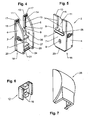
- eine perspektivische Ansicht des Grundträgers von vorne,
- Fig. 5
- eine perspektivische Ansicht des Grundträgers von hinten,
- Fig. 6
- eine perspektivische Ansicht des Haltestückes und
- Fig. 7
- eine perspektivische Ansicht der Abdeckung.
- Die in den Figuren darstellte Gurtführung 1 für ein Gurtband 2 o.dgl. Zugelement einer Verdunkelungsvorrichtung, insbesondere eines Rollladens, zur Befestigung an Rollladenkästen (nicht dargestellt) besteht u.a. aus einem im wesentlichen U-förmig ausgebildeten Grundträger 3 (
Fig. 4 und 5 ), in dem zwischen den beiden seitlichen Schenkeln 4, 5 des Grundträgers 3 eine Umlenkrolle 6 für das Gurtband 2 gelagert ist. Dabei sind in dem die beiden seitlichen Schenkel 4, 5 verbindenden Steg 7 eine Eintrittsöffnung 8 für das Gurtband 2 sowie unterhalb der Umlenkrolle 6 eine Befestigungsbohrung 9, die vorzugsweise als Langloch ausgebildet ist, vorgesehen. - In dem Steg 7 ist ein vom oberen Rand 10 des Steges 7 bis in die Eintrittsöffnung 8 verlaufender Schlitz 11 vorgesehen, an dem ein Haltestück 12 (
Fig. 6 ) mit einer Befestigungsbohrung 13 verschiebbar geführt ist. Dabei weisen die seitlichen Ränder 14 des Schlitzes 11 jeweils eine nach oben gerichtete Kante 15 auf, und diese Kanten 15 werden von seitlichen Nasen 16 des Haltestückes 12 umgriffen. An jedem Ende der Kante 15 ist ein Anschlag 17 vorgesehen, der den Schiebeweg des Haltestückes 12 begrenzt. - Am unteren Ende 18 der Gurtführung 1 bzw. des Grundträgers 3 ist zwischen den beiden Schenkeln 4, 5 eine stiftförmige Führungsachse 19 gelagert, wobei zwischen der Führungsachse 19 und einem vom unteren Ende 20 des Steges 7 rechtwinklig zu demselben verlaufenden weiteren Steg 21 die Austrittsöffnung 22 für das Gurtband 2 gebildet ist.
- In einer von dem weiteren Steg 21 und einem parallel zu demselben zwischen den Schenkel 4, 5 verlaufenden Haltesteg 23 gebildeten Nut 24 kann eine Abdichtung 25 gegen Zugluft vorgesehen sein, die beispielsweise als Bürste ausgebildet sein kann.
- An dem die beiden Schenkel 4, 5 verbindenden Steg 7 ist am unteren Rand 26 der Eintrittsöffnung 8 für das Gurtband 2 eine von den seitlichen Schenkeln 4, 5 weggerichtete Nase 27 vorgesehen, die sich an der Austrittsöffnung des Rollladenkastens abstützt (nicht dargestellt).
- Auf den Grundträger 3 ist eine Abdeckung 28 (
Fig. 7 ) aufsetzbar, die diesen umschließt, wobei die Austrittsöffnung 22 für das Gurtband 2 frei zugänglich ist. - Bei der Montage der Gurtführung 1 wird nach Demontage der zu ersetzenden Gurtführung der Grundträger 3 mit seinem Schlitz 11 bis in die Eintrittsöffnung 8 auf das Gurtband 2 aufgebracht, mittels der Nase 27 an der Austrittsöffnung des Rollladenkastens zentriert und mittels einer durch die Befestigungsbohrung 9 ragenden Schraube 29 beispielsweise in einer bereits vorhandenen Bohrung in der Wand befestigt. Nach dem Auflegen des Gurtbandes 2 auf die Umlenkrolle 6 wird das Haltestück 12 auf den Schlitz 11 und deren Kanten 15 aufgesetzt und mittels einer durch die Befestigungsbohrung 13 ragenden Schraube 29 entweder in einer weiteren bereits vorhandenen Bohrung in der Wand oder einer selbst in die Wand eingebrachten Bohrung befestigt. Danach wird zunächst, wenn noch nicht geschehen, die Abdichtung 25 in die Nut 24 eingeschoben und danach die stiftförmige Führungsachse 19 in die seitlichen Schenkel 4, 5 des Grundträgers 3 eingesetzt, wobei das Gurtband 2 zwischen der Abdichtung 25 und der Führungsachse 19 verläuft. Erst dann wird auf den Grundträger 3 die Abdeckung 28 aufgesetzt, die dafür sorgt, dass die Führungsachse 19 nicht aus dem Grundträger 3 herausfällt.
-
- 1
- Gurtführung
- 2
- Gurtband
- 3
- Grundträger
- 4
- seitlicher Schenkel von 3
- 5
- seitlicher Schenkel von 3
- 6
- Umlenkrolle von 1 in 3 zwischen 4 und 5
- 7
- Steg von 3 zwischen 4 und 5
- 8
- Eintrittsöffnung in 7 für 2
- 9
- Befestigungsbohrung in 7
- 10
- oberer Rand von 7
- 11
- Schlitz in 7 von 10 bis 8
- 12
- Haltestück von 1 an 11
- 13
- Befestigungsbohrung in 12
- 14
- seitliche Ränder von 11
- 15
- nach oben gerichtete Kanten von 14
- 16
- seitliche Nasen an 12
- 17
- Anschläge an 15
- 18
- unteres Ende von 1 bzw. 3
- 19
- Führungsachse bei 18
- 20
- unteres Ende von 7
- 21
- Steg an 7 bei 20
- 22
- Austrittsöffnung für 2
- 23
- Haltesteg
- 24
- Nut zwischen 21 und 23
- 25
- Abdichtung in 24
- 26
- unterer Rand von 8
- 27
- Nase an 26
- 28
- Abdeckung von 1
- 29
- Schraube in 9 und 13
Claims (6)
- Gurtführung für ein Gurtband o.dgl. Zugelement einer Verdunkelungsvorrichtung, insbesondere eines Rollladens, zur Befestigung an Rollladenkästen, mit einer Austrittsöffnung für das Gurtband und mit Befestigungsbohrungen, dadurch gekennzeichnet, dass die Gurtführung (1) aus einem im wesentlichen U-förmig ausgebildeten Grundträger (3) besteht, in dem zwischen den beiden seitlichen Schenkeln (4, 5) des Grundträgers (3) eine Umlenkrolle (6) für das Gurtband (2) gelagert ist, wobei in dem die beiden seitlichen Schenkel (4, 5) verbindenden Steg (7) eine Eintrittsöffnung (8) für das Gurtband (2) sowie unterhalb der Umlenkrolle (6) eine Befestigungsbohrung (9) vorgesehen sind, dass in dem Steg (7) ein vom oberen Rand (10) des Steges (7) bis in die Eintrittsöffnung (8) verlaufender Schlitz (11) vorgesehen ist, an dem ein Haltestück (12) mit einer Befestigungsbohrung (13) verschiebbar geführt ist, und dass am unteren Ende (18) der Gurtführung (1) bzw. des Grundträgers (3) zwischen den beiden Schenkeln (4, 5) eine stiftförmige Führungsachse (19) gelagert ist, wobei zwischen der Führungsachse (19) und einem vom unteren Ende (20) des Steges (7) rechtwinklig zu demselben verlaufenden weiteren Steg (21) die Austrittsöffnung (22) für das Gurtband (2) gebildet ist.
- Gurtführung nach Anspruch 1, dadurch gekennzeichnet, dass die seitlichen Ränder (14) des Schlitzes (11) jeweils eine nach oben gerichtete Kante (15) aufweisen, die von seitlichen Nasen (16) des Haltestückes (12) umgriffen werden.
- Gurtführung nach Anspruch 2, dadurch gekennzeichnet, dass in einer von dem weiteren Steg (21) und einem parallel zu demselben zwischen den Schenkeln (4, 5) verlaufenden Haltesteg (23) gebildeten Nut (24) eine Abdichtung (25) vorgesehen ist.
- Gurtführung nach Anspruch 3, dadurch gekennzeichnet, dass die Abdichtung (25) als Bürste ausgebildet ist.
- Gurtführung nach einem der Ansprüche 1 bis 4, dadurch gekennzeichnet, dass an dem die beiden seitlichen Schenkel (4, 5) verbindenden Steg (7) am unteren Rand (26) der Eintrittsöffnung (8) für das Gurtband (2) eine von den seitlichen Schenkel (4, 5) weggerichtete Nase (27) vorgesehen ist.
- Gurtführung nach einem der Ansprüche 1 bis 5, dadurch gekennzeichnet, dass auf den Grundträger (3) eine Abdeckung (28) aufsetzbar ist, die diesen umschließt, wobei die Austrittsöffnung (22) für das Gurtband (2) frei zugänglich ist.
Applications Claiming Priority (1)
| Application Number | Priority Date | Filing Date | Title |
|---|---|---|---|
| DE200720002515 DE202007002515U1 (de) | 2007-02-21 | 2007-02-21 | Gurtführung für ein Gurtband o.dgl. Zugelement einer Verdunkelungsvorrichtung, insbesondere eines Rollladens, zur Befestigung an Rollladenkästen |
Publications (3)
| Publication Number | Publication Date |
|---|---|
| EP1961911A2 true EP1961911A2 (de) | 2008-08-27 |
| EP1961911A3 EP1961911A3 (de) | 2014-01-22 |
| EP1961911B1 EP1961911B1 (de) | 2015-07-29 |
Family
ID=37990144
Family Applications (1)
| Application Number | Title | Priority Date | Filing Date |
|---|---|---|---|
| EP08002595.0A Active EP1961911B1 (de) | 2007-02-21 | 2008-02-13 | Gurtführung für ein Gurtband oder dergleichen Zugelement einer Verdunkelungsvorrichtung, insbesondere eines Rollladens, zur Befestigung an Rollladenkästen |
Country Status (3)
| Country | Link |
|---|---|
| EP (1) | EP1961911B1 (de) |
| DE (1) | DE202007002515U1 (de) |
| ES (1) | ES2549865T3 (de) |
Citations (1)
| Publication number | Priority date | Publication date | Assignee | Title |
|---|---|---|---|---|
| DE9216816U1 (de) | 1992-12-10 | 1993-02-11 | Schellenberg, Alfred, 5900 Siegen | Gurtführung für ein Gurtband an Rolladenkästen |
Family Cites Families (2)
| Publication number | Priority date | Publication date | Assignee | Title |
|---|---|---|---|---|
| DE9404879U1 (de) * | 1993-05-25 | 1994-06-01 | Geier & Trapper oHG, 91242 Ottensoos | Gurtführungseinrichtung für Rolladenkästen |
| DE202004021598U1 (de) * | 2004-07-12 | 2009-05-07 | Wetzstein, Konrad | Gurtführungsvorrichtung |
-
2007
- 2007-02-21 DE DE200720002515 patent/DE202007002515U1/de not_active Expired - Lifetime
-
2008
- 2008-02-13 EP EP08002595.0A patent/EP1961911B1/de active Active
- 2008-02-13 ES ES08002595.0T patent/ES2549865T3/es active Active
Patent Citations (1)
| Publication number | Priority date | Publication date | Assignee | Title |
|---|---|---|---|---|
| DE9216816U1 (de) | 1992-12-10 | 1993-02-11 | Schellenberg, Alfred, 5900 Siegen | Gurtführung für ein Gurtband an Rolladenkästen |
Also Published As
| Publication number | Publication date |
|---|---|
| EP1961911A3 (de) | 2014-01-22 |
| DE202007002515U1 (de) | 2007-04-19 |
| ES2549865T3 (es) | 2015-11-02 |
| EP1961911B1 (de) | 2015-07-29 |
Similar Documents
| Publication | Publication Date | Title |
|---|---|---|
| DE202010012567U1 (de) | Seilumlenkstück für einen Seilfensterheber | |
| DE102011118859B4 (de) | Beschattungsvorrichtung | |
| DE102010002817C5 (de) | Antrieb eines Fensters, einer Klappe oder dergleichen | |
| EP2120647B1 (de) | Befestigungsvorrichtung in einem möbelkorpus | |
| EP1811120B1 (de) | Rollladenkasten zum Aufsetzen auf einen Blendrahmen | |
| EP1961911B1 (de) | Gurtführung für ein Gurtband oder dergleichen Zugelement einer Verdunkelungsvorrichtung, insbesondere eines Rollladens, zur Befestigung an Rollladenkästen | |
| EP2025857B1 (de) | Führungsschiene zur Führung von Rollladenpanzern | |
| EP1985792B1 (de) | Gurtwickler für einen Rolladen | |
| DE102008021918B4 (de) | Brandschutzabdeckung | |
| EP3929396B1 (de) | Führungseinsatz für eine führungsschiene eines behangsystems; führungsschiene für ein behangsystem und ein behangsystem zum führen eines behangs | |
| EP1114910B2 (de) | Vorrichtung mit Rollladenkasten und Blendrahmen | |
| EP2113630B1 (de) | Gurtwickler für eine Verdunkelungsvorrichtung wie einen Rolladen o. dgl. | |
| EP1447508B1 (de) | Führungsschienenanordnung | |
| DE10304897B4 (de) | Vorrichtung zum Verschließen von Gebäudeöffnungen | |
| DE202004013337U1 (de) | Einrichtung zur seitlichen Führung einer Verschlußanordnung für eine Öffnung in einer Wand | |
| DE10162036C1 (de) | Vorrichtung zum Heben und Senken einer Fensterscheibe in einem Kraftfahrzeug | |
| EP2612980A2 (de) | Einlaufelement | |
| DE10050176B4 (de) | Einrastbare Führungsschiene | |
| DE202009017783U1 (de) | System zum Aufrollen von Verschlüssen für Gebäudeöffnungen | |
| DE102011103478A1 (de) | Rollobaugruppe mit einem Rollokasten, Haltebauteil zum Halten eines Rollokastens sowie Lagerschild | |
| DE10304898B4 (de) | Rollladen | |
| DE10225437B4 (de) | Befestigungsvorrichtung für Dachträger | |
| DE202006014701U1 (de) | Nachrüstsatz für Verdunkelungs- und/oder Sicherungsvorrichtungen | |
| DE102005051660B4 (de) | Vorrichtung | |
| EP3128099A1 (de) | Montagevorrichtung für eine markise |
Legal Events
| Date | Code | Title | Description |
|---|---|---|---|
| PUAI | Public reference made under article 153(3) epc to a published international application that has entered the european phase |
Free format text: ORIGINAL CODE: 0009012 |
|
| AK | Designated contracting states |
Kind code of ref document: A2 Designated state(s): AT BE BG CH CY CZ DE DK EE ES FI FR GB GR HR HU IE IS IT LI LT LU LV MC MT NL NO PL PT RO SE SI SK TR |
|
| AX | Request for extension of the european patent |
Extension state: AL BA MK RS |
|
| PUAL | Search report despatched |
Free format text: ORIGINAL CODE: 0009013 |
|
| AK | Designated contracting states |
Kind code of ref document: A3 Designated state(s): AT BE BG CH CY CZ DE DK EE ES FI FR GB GR HR HU IE IS IT LI LT LU LV MC MT NL NO PL PT RO SE SI SK TR |
|
| AX | Request for extension of the european patent |
Extension state: AL BA MK RS |
|
| RIC1 | Information provided on ipc code assigned before grant |
Ipc: E06B 9/78 20060101AFI20131217BHEP |
|
| 17P | Request for examination filed |
Effective date: 20140716 |
|
| RBV | Designated contracting states (corrected) |
Designated state(s): AT BE BG CH CY CZ DE DK EE ES FI FR GB GR HR HU IE IS IT LI LT LU LV MC MT NL NO PL PT RO SE SI SK TR |
|
| AKX | Designation fees paid |
Designated state(s): AT BE BG CH CY CZ DE DK EE ES FI FR GB GR HR HU IE IS IT LI LT LU LV MC MT NL NO PL PT RO SE SI SK TR |
|
| GRAP | Despatch of communication of intention to grant a patent |
Free format text: ORIGINAL CODE: EPIDOSNIGR1 |
|
| INTG | Intention to grant announced |
Effective date: 20150218 |
|
| GRAS | Grant fee paid |
Free format text: ORIGINAL CODE: EPIDOSNIGR3 |
|
| GRAA | (expected) grant |
Free format text: ORIGINAL CODE: 0009210 |
|
| AK | Designated contracting states |
Kind code of ref document: B1 Designated state(s): AT BE BG CH CY CZ DE DK EE ES FI FR GB GR HR HU IE IS IT LI LT LU LV MC MT NL NO PL PT RO SE SI SK TR |
|
| REG | Reference to a national code |
Ref country code: GB Ref legal event code: FG4D Free format text: NOT ENGLISH |
|
| REG | Reference to a national code |
Ref country code: CH Ref legal event code: EP |
|
| REG | Reference to a national code |
Ref country code: AT Ref legal event code: REF Ref document number: 739456 Country of ref document: AT Kind code of ref document: T Effective date: 20150815 |
|
| REG | Reference to a national code |
Ref country code: IE Ref legal event code: FG4D Free format text: LANGUAGE OF EP DOCUMENT: GERMAN |
|
| REG | Reference to a national code |
Ref country code: DE Ref legal event code: R096 Ref document number: 502008013186 Country of ref document: DE |
|
| REG | Reference to a national code |
Ref country code: LT Ref legal event code: MG4D |
|
| REG | Reference to a national code |
Ref country code: NL Ref legal event code: MP Effective date: 20150729 |
|
| PG25 | Lapsed in a contracting state [announced via postgrant information from national office to epo] |
Ref country code: GR Free format text: LAPSE BECAUSE OF FAILURE TO SUBMIT A TRANSLATION OF THE DESCRIPTION OR TO PAY THE FEE WITHIN THE PRESCRIBED TIME-LIMIT Effective date: 20151030 Ref country code: FI Free format text: LAPSE BECAUSE OF FAILURE TO SUBMIT A TRANSLATION OF THE DESCRIPTION OR TO PAY THE FEE WITHIN THE PRESCRIBED TIME-LIMIT Effective date: 20150729 Ref country code: LV Free format text: LAPSE BECAUSE OF FAILURE TO SUBMIT A TRANSLATION OF THE DESCRIPTION OR TO PAY THE FEE WITHIN THE PRESCRIBED TIME-LIMIT Effective date: 20150729 Ref country code: NO Free format text: LAPSE BECAUSE OF FAILURE TO SUBMIT A TRANSLATION OF THE DESCRIPTION OR TO PAY THE FEE WITHIN THE PRESCRIBED TIME-LIMIT Effective date: 20151029 Ref country code: LT Free format text: LAPSE BECAUSE OF FAILURE TO SUBMIT A TRANSLATION OF THE DESCRIPTION OR TO PAY THE FEE WITHIN THE PRESCRIBED TIME-LIMIT Effective date: 20150729 |
|
| REG | Reference to a national code |
Ref country code: FR Ref legal event code: PLFP Year of fee payment: 9 |
|
| PG25 | Lapsed in a contracting state [announced via postgrant information from national office to epo] |
Ref country code: PT Free format text: LAPSE BECAUSE OF FAILURE TO SUBMIT A TRANSLATION OF THE DESCRIPTION OR TO PAY THE FEE WITHIN THE PRESCRIBED TIME-LIMIT Effective date: 20151130 Ref country code: HR Free format text: LAPSE BECAUSE OF FAILURE TO SUBMIT A TRANSLATION OF THE DESCRIPTION OR TO PAY THE FEE WITHIN THE PRESCRIBED TIME-LIMIT Effective date: 20150729 Ref country code: IS Free format text: LAPSE BECAUSE OF FAILURE TO SUBMIT A TRANSLATION OF THE DESCRIPTION OR TO PAY THE FEE WITHIN THE PRESCRIBED TIME-LIMIT Effective date: 20151129 Ref country code: SE Free format text: LAPSE BECAUSE OF FAILURE TO SUBMIT A TRANSLATION OF THE DESCRIPTION OR TO PAY THE FEE WITHIN THE PRESCRIBED TIME-LIMIT Effective date: 20150729 Ref country code: PL Free format text: LAPSE BECAUSE OF FAILURE TO SUBMIT A TRANSLATION OF THE DESCRIPTION OR TO PAY THE FEE WITHIN THE PRESCRIBED TIME-LIMIT Effective date: 20150729 |
|
| PG25 | Lapsed in a contracting state [announced via postgrant information from national office to epo] |
Ref country code: NL Free format text: LAPSE BECAUSE OF FAILURE TO SUBMIT A TRANSLATION OF THE DESCRIPTION OR TO PAY THE FEE WITHIN THE PRESCRIBED TIME-LIMIT Effective date: 20150729 |
|
| PG25 | Lapsed in a contracting state [announced via postgrant information from national office to epo] |
Ref country code: EE Free format text: LAPSE BECAUSE OF FAILURE TO SUBMIT A TRANSLATION OF THE DESCRIPTION OR TO PAY THE FEE WITHIN THE PRESCRIBED TIME-LIMIT Effective date: 20150729 Ref country code: SK Free format text: LAPSE BECAUSE OF FAILURE TO SUBMIT A TRANSLATION OF THE DESCRIPTION OR TO PAY THE FEE WITHIN THE PRESCRIBED TIME-LIMIT Effective date: 20150729 Ref country code: DK Free format text: LAPSE BECAUSE OF FAILURE TO SUBMIT A TRANSLATION OF THE DESCRIPTION OR TO PAY THE FEE WITHIN THE PRESCRIBED TIME-LIMIT Effective date: 20150729 Ref country code: CZ Free format text: LAPSE BECAUSE OF FAILURE TO SUBMIT A TRANSLATION OF THE DESCRIPTION OR TO PAY THE FEE WITHIN THE PRESCRIBED TIME-LIMIT Effective date: 20150729 |
|
| REG | Reference to a national code |
Ref country code: DE Ref legal event code: R097 Ref document number: 502008013186 Country of ref document: DE |
|
| PG25 | Lapsed in a contracting state [announced via postgrant information from national office to epo] |
Ref country code: BE Free format text: LAPSE BECAUSE OF NON-PAYMENT OF DUE FEES Effective date: 20160229 Ref country code: RO Free format text: LAPSE BECAUSE OF FAILURE TO SUBMIT A TRANSLATION OF THE DESCRIPTION OR TO PAY THE FEE WITHIN THE PRESCRIBED TIME-LIMIT Effective date: 20150729 |
|
| PLBE | No opposition filed within time limit |
Free format text: ORIGINAL CODE: 0009261 |
|
| STAA | Information on the status of an ep patent application or granted ep patent |
Free format text: STATUS: NO OPPOSITION FILED WITHIN TIME LIMIT |
|
| 26N | No opposition filed |
Effective date: 20160502 |
|
| PG25 | Lapsed in a contracting state [announced via postgrant information from national office to epo] |
Ref country code: SI Free format text: LAPSE BECAUSE OF FAILURE TO SUBMIT A TRANSLATION OF THE DESCRIPTION OR TO PAY THE FEE WITHIN THE PRESCRIBED TIME-LIMIT Effective date: 20150729 |
|
| PG25 | Lapsed in a contracting state [announced via postgrant information from national office to epo] |
Ref country code: LU Free format text: LAPSE BECAUSE OF FAILURE TO SUBMIT A TRANSLATION OF THE DESCRIPTION OR TO PAY THE FEE WITHIN THE PRESCRIBED TIME-LIMIT Effective date: 20160213 Ref country code: MC Free format text: LAPSE BECAUSE OF FAILURE TO SUBMIT A TRANSLATION OF THE DESCRIPTION OR TO PAY THE FEE WITHIN THE PRESCRIBED TIME-LIMIT Effective date: 20150729 |
|
| REG | Reference to a national code |
Ref country code: CH Ref legal event code: PL |
|
| GBPC | Gb: european patent ceased through non-payment of renewal fee |
Effective date: 20160213 |
|
| PG25 | Lapsed in a contracting state [announced via postgrant information from national office to epo] |
Ref country code: LI Free format text: LAPSE BECAUSE OF NON-PAYMENT OF DUE FEES Effective date: 20160229 Ref country code: CH Free format text: LAPSE BECAUSE OF NON-PAYMENT OF DUE FEES Effective date: 20160229 |
|
| REG | Reference to a national code |
Ref country code: IE Ref legal event code: MM4A |
|
| PG25 | Lapsed in a contracting state [announced via postgrant information from national office to epo] |
Ref country code: IE Free format text: LAPSE BECAUSE OF NON-PAYMENT OF DUE FEES Effective date: 20160213 Ref country code: GB Free format text: LAPSE BECAUSE OF NON-PAYMENT OF DUE FEES Effective date: 20160213 |
|
| REG | Reference to a national code |
Ref country code: FR Ref legal event code: PLFP Year of fee payment: 10 |
|
| REG | Reference to a national code |
Ref country code: AT Ref legal event code: MM01 Ref document number: 739456 Country of ref document: AT Kind code of ref document: T Effective date: 20160213 |
|
| PG25 | Lapsed in a contracting state [announced via postgrant information from national office to epo] |
Ref country code: AT Free format text: LAPSE BECAUSE OF NON-PAYMENT OF DUE FEES Effective date: 20160213 |
|
| PG25 | Lapsed in a contracting state [announced via postgrant information from national office to epo] |
Ref country code: MT Free format text: LAPSE BECAUSE OF FAILURE TO SUBMIT A TRANSLATION OF THE DESCRIPTION OR TO PAY THE FEE WITHIN THE PRESCRIBED TIME-LIMIT Effective date: 20150729 |
|
| REG | Reference to a national code |
Ref country code: FR Ref legal event code: PLFP Year of fee payment: 11 |
|
| PG25 | Lapsed in a contracting state [announced via postgrant information from national office to epo] |
Ref country code: HU Free format text: LAPSE BECAUSE OF FAILURE TO SUBMIT A TRANSLATION OF THE DESCRIPTION OR TO PAY THE FEE WITHIN THE PRESCRIBED TIME-LIMIT; INVALID AB INITIO Effective date: 20080213 Ref country code: CY Free format text: LAPSE BECAUSE OF FAILURE TO SUBMIT A TRANSLATION OF THE DESCRIPTION OR TO PAY THE FEE WITHIN THE PRESCRIBED TIME-LIMIT Effective date: 20150729 |
|
| PG25 | Lapsed in a contracting state [announced via postgrant information from national office to epo] |
Ref country code: TR Free format text: LAPSE BECAUSE OF FAILURE TO SUBMIT A TRANSLATION OF THE DESCRIPTION OR TO PAY THE FEE WITHIN THE PRESCRIBED TIME-LIMIT Effective date: 20150729 |
|
| PG25 | Lapsed in a contracting state [announced via postgrant information from national office to epo] |
Ref country code: BG Free format text: LAPSE BECAUSE OF FAILURE TO SUBMIT A TRANSLATION OF THE DESCRIPTION OR TO PAY THE FEE WITHIN THE PRESCRIBED TIME-LIMIT Effective date: 20150729 |
|
| REG | Reference to a national code |
Ref country code: DE Ref legal event code: R082 Ref document number: 502008013186 Country of ref document: DE Representative=s name: ARROBA GBR, DE |
|
| PGFP | Annual fee paid to national office [announced via postgrant information from national office to epo] |
Ref country code: FR Payment date: 20210223 Year of fee payment: 14 Ref country code: IT Payment date: 20210226 Year of fee payment: 14 |
|
| PGFP | Annual fee paid to national office [announced via postgrant information from national office to epo] |
Ref country code: ES Payment date: 20210301 Year of fee payment: 14 |
|
| PG25 | Lapsed in a contracting state [announced via postgrant information from national office to epo] |
Ref country code: FR Free format text: LAPSE BECAUSE OF NON-PAYMENT OF DUE FEES Effective date: 20220228 |
|
| REG | Reference to a national code |
Ref country code: ES Ref legal event code: FD2A Effective date: 20230329 |
|
| PG25 | Lapsed in a contracting state [announced via postgrant information from national office to epo] |
Ref country code: ES Free format text: LAPSE BECAUSE OF NON-PAYMENT OF DUE FEES Effective date: 20220214 |
|
| PG25 | Lapsed in a contracting state [announced via postgrant information from national office to epo] |
Ref country code: IT Free format text: LAPSE BECAUSE OF NON-PAYMENT OF DUE FEES Effective date: 20220213 |
|
| PGFP | Annual fee paid to national office [announced via postgrant information from national office to epo] |
Ref country code: DE Payment date: 20250207 Year of fee payment: 18 |