EP1961602A1 - In-wheel motor system - Google Patents
In-wheel motor system Download PDFInfo
- Publication number
- EP1961602A1 EP1961602A1 EP06834430A EP06834430A EP1961602A1 EP 1961602 A1 EP1961602 A1 EP 1961602A1 EP 06834430 A EP06834430 A EP 06834430A EP 06834430 A EP06834430 A EP 06834430A EP 1961602 A1 EP1961602 A1 EP 1961602A1
- Authority
- EP
- European Patent Office
- Prior art keywords
- motor
- wheel
- gear mechanism
- reduction gear
- shock absorbing
- Prior art date
- Legal status (The legal status is an assumption and is not a legal conclusion. Google has not performed a legal analysis and makes no representation as to the accuracy of the status listed.)
- Withdrawn
Links
Images


Classifications
-
- F—MECHANICAL ENGINEERING; LIGHTING; HEATING; WEAPONS; BLASTING
- F16—ENGINEERING ELEMENTS AND UNITS; GENERAL MEASURES FOR PRODUCING AND MAINTAINING EFFECTIVE FUNCTIONING OF MACHINES OR INSTALLATIONS; THERMAL INSULATION IN GENERAL
- F16F—SPRINGS; SHOCK-ABSORBERS; MEANS FOR DAMPING VIBRATION
- F16F7/00—Vibration-dampers; Shock-absorbers
- F16F7/10—Vibration-dampers; Shock-absorbers using inertia effect
- F16F7/1028—Vibration-dampers; Shock-absorbers using inertia effect the inertia-producing means being a constituent part of the system which is to be damped
-
- B—PERFORMING OPERATIONS; TRANSPORTING
- B60—VEHICLES IN GENERAL
- B60G—VEHICLE SUSPENSION ARRANGEMENTS
- B60G3/00—Resilient suspensions for a single wheel
- B60G3/18—Resilient suspensions for a single wheel with two or more pivoted arms, e.g. parallelogram
- B60G3/20—Resilient suspensions for a single wheel with two or more pivoted arms, e.g. parallelogram all arms being rigid
-
- B—PERFORMING OPERATIONS; TRANSPORTING
- B60—VEHICLES IN GENERAL
- B60K—ARRANGEMENT OR MOUNTING OF PROPULSION UNITS OR OF TRANSMISSIONS IN VEHICLES; ARRANGEMENT OR MOUNTING OF PLURAL DIVERSE PRIME-MOVERS IN VEHICLES; AUXILIARY DRIVES FOR VEHICLES; INSTRUMENTATION OR DASHBOARDS FOR VEHICLES; ARRANGEMENTS IN CONNECTION WITH COOLING, AIR INTAKE, GAS EXHAUST OR FUEL SUPPLY OF PROPULSION UNITS IN VEHICLES
- B60K17/00—Arrangement or mounting of transmissions in vehicles
- B60K17/02—Arrangement or mounting of transmissions in vehicles characterised by arrangement, location, or kind of clutch
-
- B—PERFORMING OPERATIONS; TRANSPORTING
- B60—VEHICLES IN GENERAL
- B60K—ARRANGEMENT OR MOUNTING OF PROPULSION UNITS OR OF TRANSMISSIONS IN VEHICLES; ARRANGEMENT OR MOUNTING OF PLURAL DIVERSE PRIME-MOVERS IN VEHICLES; AUXILIARY DRIVES FOR VEHICLES; INSTRUMENTATION OR DASHBOARDS FOR VEHICLES; ARRANGEMENTS IN CONNECTION WITH COOLING, AIR INTAKE, GAS EXHAUST OR FUEL SUPPLY OF PROPULSION UNITS IN VEHICLES
- B60K17/00—Arrangement or mounting of transmissions in vehicles
- B60K17/04—Arrangement or mounting of transmissions in vehicles characterised by arrangement, location or kind of gearing
- B60K17/043—Transmission unit disposed in on near the vehicle wheel, or between the differential gear unit and the wheel
- B60K17/046—Transmission unit disposed in on near the vehicle wheel, or between the differential gear unit and the wheel with planetary gearing having orbital motion
-
- B—PERFORMING OPERATIONS; TRANSPORTING
- B60—VEHICLES IN GENERAL
- B60K—ARRANGEMENT OR MOUNTING OF PROPULSION UNITS OR OF TRANSMISSIONS IN VEHICLES; ARRANGEMENT OR MOUNTING OF PLURAL DIVERSE PRIME-MOVERS IN VEHICLES; AUXILIARY DRIVES FOR VEHICLES; INSTRUMENTATION OR DASHBOARDS FOR VEHICLES; ARRANGEMENTS IN CONNECTION WITH COOLING, AIR INTAKE, GAS EXHAUST OR FUEL SUPPLY OF PROPULSION UNITS IN VEHICLES
- B60K17/00—Arrangement or mounting of transmissions in vehicles
- B60K17/30—Arrangement or mounting of transmissions in vehicles the ultimate propulsive elements, e.g. ground wheels, being steerable
- B60K17/303—Arrangement or mounting of transmissions in vehicles the ultimate propulsive elements, e.g. ground wheels, being steerable with a gearwheel on the steering knuckle or kingpin axis
-
- B—PERFORMING OPERATIONS; TRANSPORTING
- B60—VEHICLES IN GENERAL
- B60K—ARRANGEMENT OR MOUNTING OF PROPULSION UNITS OR OF TRANSMISSIONS IN VEHICLES; ARRANGEMENT OR MOUNTING OF PLURAL DIVERSE PRIME-MOVERS IN VEHICLES; AUXILIARY DRIVES FOR VEHICLES; INSTRUMENTATION OR DASHBOARDS FOR VEHICLES; ARRANGEMENTS IN CONNECTION WITH COOLING, AIR INTAKE, GAS EXHAUST OR FUEL SUPPLY OF PROPULSION UNITS IN VEHICLES
- B60K7/00—Disposition of motor in, or adjacent to, traction wheel
- B60K7/0007—Disposition of motor in, or adjacent to, traction wheel the motor being electric
-
- H—ELECTRICITY
- H02—GENERATION; CONVERSION OR DISTRIBUTION OF ELECTRIC POWER
- H02K—DYNAMO-ELECTRIC MACHINES
- H02K7/00—Arrangements for handling mechanical energy structurally associated with dynamo-electric machines, e.g. structural association with mechanical driving motors or auxiliary dynamo-electric machines
- H02K7/003—Couplings; Details of shafts
-
- B—PERFORMING OPERATIONS; TRANSPORTING
- B60—VEHICLES IN GENERAL
- B60G—VEHICLE SUSPENSION ARRANGEMENTS
- B60G2204/00—Indexing codes related to suspensions per se or to auxiliary parts
- B60G2204/10—Mounting of suspension elements
- B60G2204/18—Mounting of vehicle engines
- B60G2204/182—Electric motor on wheel support
-
- B—PERFORMING OPERATIONS; TRANSPORTING
- B60—VEHICLES IN GENERAL
- B60G—VEHICLE SUSPENSION ARRANGEMENTS
- B60G2204/00—Indexing codes related to suspensions per se or to auxiliary parts
- B60G2204/10—Mounting of suspension elements
- B60G2204/30—In-wheel mountings
-
- B—PERFORMING OPERATIONS; TRANSPORTING
- B60—VEHICLES IN GENERAL
- B60K—ARRANGEMENT OR MOUNTING OF PROPULSION UNITS OR OF TRANSMISSIONS IN VEHICLES; ARRANGEMENT OR MOUNTING OF PLURAL DIVERSE PRIME-MOVERS IN VEHICLES; AUXILIARY DRIVES FOR VEHICLES; INSTRUMENTATION OR DASHBOARDS FOR VEHICLES; ARRANGEMENTS IN CONNECTION WITH COOLING, AIR INTAKE, GAS EXHAUST OR FUEL SUPPLY OF PROPULSION UNITS IN VEHICLES
- B60K7/00—Disposition of motor in, or adjacent to, traction wheel
- B60K2007/0053—Disposition of motor in, or adjacent to, traction wheel the motor moving relative to the vehicle body and to the wheel axle
-
- B—PERFORMING OPERATIONS; TRANSPORTING
- B60—VEHICLES IN GENERAL
- B60K—ARRANGEMENT OR MOUNTING OF PROPULSION UNITS OR OF TRANSMISSIONS IN VEHICLES; ARRANGEMENT OR MOUNTING OF PLURAL DIVERSE PRIME-MOVERS IN VEHICLES; AUXILIARY DRIVES FOR VEHICLES; INSTRUMENTATION OR DASHBOARDS FOR VEHICLES; ARRANGEMENTS IN CONNECTION WITH COOLING, AIR INTAKE, GAS EXHAUST OR FUEL SUPPLY OF PROPULSION UNITS IN VEHICLES
- B60K7/00—Disposition of motor in, or adjacent to, traction wheel
- B60K2007/0092—Disposition of motor in, or adjacent to, traction wheel the motor axle being coaxial to the wheel axle
-
- B—PERFORMING OPERATIONS; TRANSPORTING
- B60—VEHICLES IN GENERAL
- B60L—PROPULSION OF ELECTRICALLY-PROPELLED VEHICLES; SUPPLYING ELECTRIC POWER FOR AUXILIARY EQUIPMENT OF ELECTRICALLY-PROPELLED VEHICLES; ELECTRODYNAMIC BRAKE SYSTEMS FOR VEHICLES IN GENERAL; MAGNETIC SUSPENSION OR LEVITATION FOR VEHICLES; MONITORING OPERATING VARIABLES OF ELECTRICALLY-PROPELLED VEHICLES; ELECTRIC SAFETY DEVICES FOR ELECTRICALLY-PROPELLED VEHICLES
- B60L2220/00—Electrical machine types; Structures or applications thereof
- B60L2220/40—Electrical machine applications
- B60L2220/44—Wheel Hub motors, i.e. integrated in the wheel hub
-
- B—PERFORMING OPERATIONS; TRANSPORTING
- B60—VEHICLES IN GENERAL
- B60L—PROPULSION OF ELECTRICALLY-PROPELLED VEHICLES; SUPPLYING ELECTRIC POWER FOR AUXILIARY EQUIPMENT OF ELECTRICALLY-PROPELLED VEHICLES; ELECTRODYNAMIC BRAKE SYSTEMS FOR VEHICLES IN GENERAL; MAGNETIC SUSPENSION OR LEVITATION FOR VEHICLES; MONITORING OPERATING VARIABLES OF ELECTRICALLY-PROPELLED VEHICLES; ELECTRIC SAFETY DEVICES FOR ELECTRICALLY-PROPELLED VEHICLES
- B60L2220/00—Electrical machine types; Structures or applications thereof
- B60L2220/40—Electrical machine applications
- B60L2220/46—Wheel motors, i.e. motor connected to only one wheel
-
- H—ELECTRICITY
- H02—GENERATION; CONVERSION OR DISTRIBUTION OF ELECTRIC POWER
- H02K—DYNAMO-ELECTRIC MACHINES
- H02K7/00—Arrangements for handling mechanical energy structurally associated with dynamo-electric machines, e.g. structural association with mechanical driving motors or auxiliary dynamo-electric machines
- H02K7/10—Structural association with clutches, brakes, gears, pulleys or mechanical starters
- H02K7/116—Structural association with clutches, brakes, gears, pulleys or mechanical starters with gears
-
- Y—GENERAL TAGGING OF NEW TECHNOLOGICAL DEVELOPMENTS; GENERAL TAGGING OF CROSS-SECTIONAL TECHNOLOGIES SPANNING OVER SEVERAL SECTIONS OF THE IPC; TECHNICAL SUBJECTS COVERED BY FORMER USPC CROSS-REFERENCE ART COLLECTIONS [XRACs] AND DIGESTS
- Y02—TECHNOLOGIES OR APPLICATIONS FOR MITIGATION OR ADAPTATION AGAINST CLIMATE CHANGE
- Y02T—CLIMATE CHANGE MITIGATION TECHNOLOGIES RELATED TO TRANSPORTATION
- Y02T10/00—Road transport of goods or passengers
- Y02T10/60—Other road transportation technologies with climate change mitigation effect
- Y02T10/64—Electric machine technologies in electromobility
Definitions
- the present invention relates to an in-wheel motor system equipped with a wheel driving motor adjoining a wheel and, more particularly, to an in-wheel motor system so structured as to support the motor through the medium of a shock absorbing mechanism or a shock absorbing member with respect to the around-the-wheel parts of a vehicle.
- in-wheel motor systems are increasingly introduced into motor-driven vehicles such as electric vehicles.
- Those in-wheel motor systems typically have an electric motor or a geared driving motor or the like, which integrally incorporates an electric motor and a planetary reducer within a motor case, adjoining a wheel.
- suspension mechanisms such as springs around the wheels
- unsprung mass which is the mass of unsprung parts such as wheels, knuckles and suspension arms
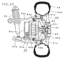
- FIG. 10 illustrates a structural example of an in-wheel motor system which is provided with a wheel support system having a conventional double wishbone suspension.
- a motor case 50c for a geared motor (in-wheel motor) 50 which integrally incorporates an electric motor 50a and a planetary reducer 50b within the motor case 50c, is mounted at the top and the bottom to motor mounts 51a and 51b, which are each a rubber or spring member expandible and contractible in the vertical direction of the vehicle.
- the motor mounts 51a and 51b and knuckles 52 are connected to upper and lower suspension arms 54a and 54b via ball joints 53a and 53b, so that the motor 50 is floating-mounted between the knuckles 52, which are an unsprung part as mentioned above, thus having the motor 50 act as a weight of a dynamic damper.
- an output shaft 50j of the planetary reducer 50b is connected to a wheel hub 57 mounted on a wheel disk 56a of a wheel 56 via a constant-velocity joint 55, so that the drive force of the motor 50 can be steadily transmitted to the wheel 56.
- the numeral 58 denotes a tire fitted to a rim 56b of the wheel 56 and numeral 59 a suspension member consisting of a shock absorber or the like mounted on the upper and lower suspension arms 54a and 54b.
- a planetary reducer 50b with large output torque and a wheel 56 are coupled to each other by a constant-velocity joint 55, which is a power transmission mechanism.
- the large load torque of the power transmission mechanism presents a problem of durability.
- the characteristics of a motor, the reduction ratio of a reduction gear mechanism, and the like must be selected to meet the tire size, necessary torque and so on.
- an electric motor 51a and a planetary reducer 50b are integrally structured together, so that there is a problem of inability to replace the electric motor 51a and the planetary reducer 50b separately.
- the present invention has been made in view of these conventional problems, and an object thereof is to provide an in-wheel motor system that not only excels in space efficiency but also provides a reliable "floating-mounting" of a motor with respect to the unsprung parts of a vehicle.
- an in-wheel motor system comprising an electric motor and a reduction gear mechanism for reducing the rotation speed of an output shaft of the motor and transmitting the motive power of the motor to the wheel, wherein the motive power of the motor is transmitted to the wheel through the reduction gear mechanism, and wherein a motor case supporting the stator side of the motor is mounted on an unsprung part of a vehicle through the medium of a shock absorbing member or a shock absorbing mechanism and a casing of the reduction gear mechanism is integrally structured together with a knuckle which is coupled to a suspension mechanism of the vehicle.
- an in-wheel motor system wherein the casing of the reduction gear mechanism and the motor case are structured as separate units.
- an in-wheel motor system wherein the motor and the reduction gear mechanism are connected to each other by a flexible coupling.
- a motor mounting member is disposed on a strut suspending the knuckle from a vehicle body and the shock absorbing member or shock absorbing mechanism is disposed between the motor mounting member and the upper face side of the motor case.
- an in-wheel motor system wherein the reduction gear mechanism is constituted by a first reduction gear mechanism directly connected to an output shaft of the motor and a second reduction gear mechanism connecting the first reduction gear mechanism to the wheel.
- a planetary gear mechanism is used as the reduction gear mechanism.
- an in-wheel motor system wherein the upper face side of the motor case supporting the stator side of the motor is connected to a knuckle coupled to a wheel section by a shock absorbing mechanism equipped with a spring member and a damper and the spring member is disposed at the center of the motor case in the tire fore-aft direction on the upper face side thereof.
- the shock absorbing mechanism is provided with a guide member for guiding the operating direction of the spring member and the damper and the spring member, the damper, and the guide member are disposed between the motor case and the motor mounting member.
- an in-wheel motor system wherein the shock absorbing mechanism is provided with a guide member for guiding the operating direction of the spring member and the damper and the guide member is disposed in symmetrical positions with respect to the center of the spring member in the tire fore-aft direction on the upper face side of the motor case.
- an in-wheel motor system wherein the drive force of the motor is transmitted to the wheel through the medium of a flexible coupling.
- an in-wheel motor system incorporated into a drive wheel comprising an electric motor and a reduction gear mechanism connected to an output shaft of the electric motor for reducing the rotation speed of the motor and transmitting it to a wheel, wherein the motor and the reduction gear mechanism are connected to each other by a flexible coupling, and wherein a motor case supporting the stator side of the motor and an unsprung part of a vehicle are connected to each other by a shock absorbing mechanism equipped with a spring member and a damper, whereby the mass of the motor acts as the mass of a dynamic damper.
- an in-wheel motor system wherein a motor mounting member is disposed on a strut suspending the knuckle, which is an unsprung member of a vehicle, from a vehicle body and the motor case supporting the stator side of the motor is mounted to the motor mounting member through the medium of a shock absorbing mechanism, whereby the mass of the motor acts as the mass of a dynamic damper.
- the motive power of an electric motor is transmitted to a wheel through the medium of a reduction gear mechanism.
- the motor case supporting the stator side of the motor is floating-mounted with respect to the unsprung portion of a vehicle, with the motor case connected to a knuckle coupled to a wheel section or to a motor mounting member provided on a strut suspending a knuckle from a vehicle body by a shock absorbing member or a shock absorbing mechanism equipped with a spring member and a damper.
- a casing of the reduction gear mechanism is integrally structured together with a knuckle coupled to the suspension mechanism of the vehicle, then it will be possible to replace the motor and the reduction gear mechanism separately. This makes it possible to use the same motor for wheels of different tire diameters or change the output torque by changing the reduction gear mechanism only. Also, with the structure of the present invention employed, the motor only will be mounted on the unsprung portion of the vehicle, so that the durability of the power transmission mechanism, such as a flexible coupling, that couples the electric motor to the reduction gear mechanism can be improved.
- the reduction gear mechanism may be constituted by a first reduction gear mechanism connected directly to the output shaft of the motor and a second reduction gear mechanism connecting the first reduction gear mechanism to the wheel, and the rotation speed of the electric motor may be reduced in two stages and transmitted to the wheel. Then, even when a small motor of high rotation speed and low torque is used, a large drive force can be produced without the use of a reduction gear mechanism of a larger diameter.
- planetary gear mechanisms may be used as the first and second reduction gear mechanisms. Then, the motor shaft and the gear shaft are coaxial with each other, so that the diameter of the gear housing will never greatly exceed that of the motor housing, thus ensuring even higher space efficiency.
- the upper face side of the motor case and the knuckle coupled to a wheel section may be connected to each other by a shock absorbing mechanism equipped with a damper and a spring member and the spring member may be disposed on the upper face side of the motor case and at the center of the motor case in the tire fore-aft direction. Then the space efficiency may not only rise, but also the mass of the motor may act stably as the mass of a dynamic damper.
- the shock absorbing mechanism may be provided with a guide member for guiding the operating direction of the spring member and the damper, and the spring member, the damper and the guide member may be disposed not only between the motor case and the motor mounting member but also on the upper face side of the motor case and in symmetrical positions with respect to the center of the spring member in the tire fore-aft direction. Then the spring member and the damper can be guided reliably in the up-and-down direction, so that the mass of the motor may function sufficiently as the mass of a dynamic damper.
- the motor is mounted on the knuckle through the medium of a shock absorbing mechanism. Therefore, if the drive force of the motor is transmitted to the wheel by connecting the motor to the wheel by a power transmission mechanism such as a universal joint or a flexible coupling, then the drive force of the motor can be transmitted to the wheel steadily.
- the electric motor which is the source of drive
- the reduction gear mechanism which transmits the rotation force of the motor to the wheel
- the motor case supporting the stator side of the motor may be connected to a knuckle coupled to a wheel section or to a motor mounting member provided on a strut suspending a knuckle from the vehicle body by means of a shock absorbing mechanism equipped with a spring member and a damper.
- This arrangement may separate the mass of the reduction gear mechanism from the mass of the motor, thereby allowing the mass of the motor alone to act as the mass of the dynamic damper.
- FIG. 1 is a vertical sectional view showing a structure of an in-wheel motor system according to Embodiment 1
- FIG. 2 is a perspective illustration thereof.
- reference numeral 1 denotes a tire
- 2 a wheel composed of a rim 2a and a wheel disk 2b
- 3 a wheel hub connected to the wheel 2 at the rotary shaft thereof
- 4 a strut having a coil spring 4a and a shock absorber 4b and suspending a knuckle 5 connected thereto via the wheel hub 3 and a bearing 5j from a vehicle body
- 6 a brake mechanism mounted to the wheel hub 3
- 7 an upper arm connected to the strut 4
- 8 a lower arm supporting the knuckle 5 from below.
- reference numeral 10 denotes an electric motor provided with a motor case 10a supporting the stator 10S side thereof, an output shaft 10 rotatably mounted on the motor case 10a by bearings 10j, and a rotor 10R mounted on the output shaft 10b
- 11 denotes a reduction gear mechanism provided with a first planetary gear mechanism 11a connected to the output shaft 10b of the motor 10 and a secondary planetary gear mechanism 11b connecting the first planetary gear mechanism 11a to the wheel hub 3 for reducing the rotation speed of the motor 10 and transmitting it to the wheel 2.
- the electric motor 10 and the reduction gear mechanism 11 are placed in separate casings, and the electric motor 10 and the reduction gear mechanism 11 are connected to each other by a flexible coupling 12, which is a power transmission mechanism such as an Oldham's coupling.
- a casing 11c of the reduction gear mechanism 11 is integrally structured together with the knuckle 5, and by providing a motor mounting member 4m on the lower part of the strut 4, the motor case 10a supporting the stator 10S side of the motor 10 is mounted to the motor mounting member 4m through the medium of a shock absorbing mechanism 20 to be described in detail below. Accordingly, removal of the flexible coupling 12 allows separation of the electric motor 10 and the reduction gear mechanism 11 from each other, so that it becomes possible to replace the motor 10 and the reduction gear mechanism 11, which is integrated with the knuckle 5, separately.
- the shock absorbing mechanism 20 includes a spring member 21 which is a coil spring, a damper 22 which has a cylinder 22a, a not-shown piston, and a shaft 22b coupled with the piston, and two guide members 23 (23A and 23B) consisting of a fixed part 23a and a guide shaft 23b for guiding the operation of the spring member 21 and the damper 22 in an up-and-down direction.
- a spring member 21 which is a coil spring
- a damper 22 which has a cylinder 22a, a not-shown piston, and a shaft 22b coupled with the piston
- two guide members 23 23A and 23B
- one end of the spring member 21 is mounted to the motor mounting member 4m, and the other end thereof to the central portion of the upper face side (strut 4 side) of the motor case 10a.
- the cylinder 22a of the damper 22 is mounted to one side face of the motor case 10a, and one end of the shaft 22b to one end of the motor mounting member 4m.
- the two guide members 23,23 are disposed symmetrically in the tire fore-aft direction with the spring member 21 in the middle. That is, the fixed parts 23a,23a of the guide members 23,23 are attached respectively to the motor mounting member 4m, and the guide shafts 23b,23b thereof are installed upright on the motor case 10a.
- the present embodiment uses an arrangement such that one spring member 21 is mounted to a central portion of the upper face side of the motor case 10a and two guide members 23A and 23B are disposed on both sides thereof, so that the spring member 21 can be guided steadily in the up-and-down direction.
- the motor 10 functions sufficiently as a dynamic damper, which not only improves markedly the ground contact performance and riding comfort of a vehicle running on a rough road, but also simplifies the structure of a shock absorbing mechanism 20.
- the planetary gear mechanism 11a (11b) includes a sun gear 11p, planetary gears 11z which, connected to the sun gear 11p mounted to the input shaft by arms 11q, revolve around the shaft of the sun gear 11p through the space between the sun gear 11p and a ring gear 11r mounted to the inner surface of a not-shown gear housing, and a carrier 11k connected to the planetary gears 11z and mounted to the output shaft.
- the planetary gear mechanism 11a (11b) is a mechanism for reducing the rotation speed of the sun gear 11p to a rotation speed which corresponds to the period of revolution of the planetary gears 11z.
- the carrier 11k of the second planetary gear mechanism 11b is coupled to a rotary shaft 3k of a wheel hub 3 by a spline coupling or a serration coupling, and thus the rotation of the electric motor 10 is transmitted to the wheel 2.
- the reduction gear mechanism may also be a parallel shaft gear mechanism 70 as shown in FIG. 4 .
- the parallel shaft gear mechanism 70 there need to be an output shaft J of the motor, a counter shaft 71, which is a shaft other than the former, and gears 72a and 72b.
- a gear housing 11c may have a larger diameter, which presents the possibility of interference with peripheral members such as the knuckle 5.
- the present embodiment uses planetary gear mechanisms 11a and 11b as the reduction gear mechanism, so that the motor shaft and the gear shaft are coaxial with each other and thus the diameter of the gear housing will never greatly exceed that of the motor housing.
- the freedom of layout can not only be greater, but the space efficiency can also be enhanced.
- the first planetary gear mechanism 11a and the second planetary gear mechanism 11b are connected to each other in series.
- the input shaft of the first planetary gear mechanism 11a is connected to the output shaft 10b of the electric motor 10, and the carrier 11k of the first planetary gear mechanism 11a is connected to the input shaft of the second planetary gear mechanism 11b.
- the output torque of the first planetary gear mechanism 11a can be made larger at the second planetary gear mechanism 11b before it is transmitted to the wheel 2.
- the wheel can be driven adequately, and furthermore the rotation speed is reduced in two stages, so that the rotation speed of the motor can be raised. Therefore, it is possible that an adequate drive force can be produced even when the electric motor 10 used is a small, light-weight motor of high rotation speed and low torque.
- a rotary drive mechanism combining an electric motor 10 and a reduction gear mechanism 11 it is possible to use a small motor of higher rotation speed and lower torque than those of a direct-drive motor driving a wheel 2 directly.
- a planetary reducer 50b of large output torque is coupled to a wheel 56 by a constant-velocity oint 55, which is a power transmission mechanism, and therefore the load torque of the power transmission mechanism is large.
- a flexible coupling 12 which is the power transmission mechanism of the present embodiment, connects a small electric motor 10 of low torque to a reduction gear mechanism 11. Therefore the load torque is small, and hence the durability of the power transmission mechanism can be improved.
- the output of the reduction gear mechanism 11 is transmitted directly to the wheel 2, the drive efficiency is improved over that of the conventional system.
- the use of a reduction gear mechanism 11, which is a twin arrangement of a first gear mechanism 11a and a second gear mechanism 11b connected in series can make the electric motor 10 even more small-size and light-weight. Therefore the load torque acting on the flexible coupling can be made smaller, and the durability thereof further improved.
- the motor case 10a when elastically supporting the electric motor 10 separated from the mass of the reduction gear mechanism 11, it is sufficient to support the motor case 10a from above only, as stated above. This not only makes the shock absorbing mechanism 20 smaller and lighter-weight, but also improves the space efficiency.
- the electric motor 10 and the reduction gear mechanism 11 are placed in separate casings, and the electric motor 10 and the reduction gear mechanism 11 are connected to each other by a flexible coupling 12 such as an Oldham's coupling, which is a power transmission mechanism.
- a motor mounting member 4m is provided on the lower part of the strut 4 and the motor case 10a supporting the stator 10S side of the motor 10 is mounted on the motor mounting member 4m through the medium of shock absorbing mechanism 20.
- a casing 11c of the reduction gear mechanism 11 is integrally structured together with the knuckle 5, so that the load torque can be made smaller, and the durability thereof can be improved.
- a motor mounting member 4m is provided on the lower part of a strut 4 suspending the knuckle 5, and the motor 10 is mounted on the motor mounting member 4m through the medium of a shock absorbing mechanism 20 equipped with two guide members 23A and 23B for guiding the operating direction of a spring member 21 and a damper 22, thereby having only the mass of the motor 10 act as the mass of the dynamic damper.
- a reduction gear mechanism 11 which transmits the rotation of the electric motor 10 to the wheel 2 is constituted by a first planetary gear mechanism 11a connected to the output shaft 10b of the electric motor 10 and a second planetary gear mechanism 11b connecting the first planetary gear mechanism 11a to the wheel hub 3.
- the reduction gear mechanism 11 and the electric motor 10, which are integrally structured together, are mounted to the knuckle 5.
- an electric motor 10 and a reduction gear mechanism 11 are placed in separate casings. And, by providing a motor mounting member 4m on the lower part of a strut 4, a motor case 10a supporting the stator 10S side of the motor 10 is mounted on the motor mounting member 4m through the medium of a shock absorbing mechanism 20. Also, a casing 11c of the reduction gear mechanism 11 is integrally structured together with a knuckle 5. In Embodiment 2, however, as shown in FIG. 5 and FIG.
- an electric motor 10 and a reduction gear mechanism 11 may be coupled with each other by a flexible coupling 12, and a motor case 10a supporting the stator 10S side of the motor 10 may be mounted to the motor mounting member 4m through the medium of a shock absorbing mechanism 20. And also a casing 11c of the reduction gear mechanism 11 may be fixed to a knuckle 5. In this embodiment, too, the reduction gear mechanism 11 is separated from the electric motor 10 by the flexible coupling 12.
- a carrier 11k connected to a not-shown ring gear of a second gear mechanism 11b of the reduction gear mechanism 11 may be coupled to a rotary shaft 3k of a wheel hub 3 by a spline coupling or a serration coupling, and thus the rotation force of the electric motor 10 can be transmitted to a wheel 2 while making allowance for the axial movement of the rotary shaft 3k.
- a single spring member 21 of the shock absorbing mechanism 20 may be mounted to a central portion of the upper face side of the motor case 10a, and two guide members 23A and 23B are disposed on both sides thereof, so that spring member 21 can be guided steadily in the up-and-down direction.
- the motor 10 is allowed to function sufficiently as a dynamic damper, and also the structure of the shock absorbing mechanism 20 can be simplified.
- the suspension used to suspend wheels from the vehicle body is of a strut type.
- the present invention is not limited to such a structure, but is also applicable to vehicles with suspensions of other structures such as double wishbone suspensions.
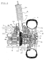
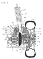
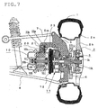
- double wishbone suspensions as shown in FIG. 7 and FIG.
- a motor mounting member 5m may be provided in the vicinity of the connecting point of a knuckle 5 and an upper arm 7, and the motor mounting member 5m and a motor case 10a may be connected with each other by a shock absorbing member 20, or otherwise the arrangement may be such that the upper side of the knuckle 5 is so formed as to protrude in the direction of the electric motor 10 and the shock absorbing member 20 is mounted to this protruding portion.
- the two guide members 23A and 23B it is important for the two guide members 23A and 23B to be disposed symmetrically with respect to the center of the motor case 10c in the tire fore-aft direction. As a result, the electric motor 10 can be stably floating-mounted with respect to the knuckle 5.
- the space efficiency can be improved by disposing two of the spring members 21 between the fixed parts 23a,23a and the motor case 10a around the periphery of the guide shafts 23b,23b of the guide members 23A and 23B.
- a light-weight electric motor 10 only is suspended from a strut 4 or a knuckle 5, so that a single unit of spring member 21 or damper 22 suffices for the purpose thereof. Moreover, their being only one provides the advantage of fewer constituent parts and easier assembly.
- the reduction gear mechanism 11 is in a twin arrangement.
- a single reduction gear mechanism as shown in FIG. 7 and FIG. 8 may suffice.
- the mass of the electric motor 10 and the mass of the reduction gear mechanism 11 are separated from each other by the flexible coupling 12.
- the electric motor 10 can function sufficiently as a dynamic damper.
- the electric motor 10 and the reduction gear mechanism 11 are connected to each other by a flexible coupling 12.
- the power transmission mechanism connecting the electric motor 10 and the reduction gear mechanism 11 is not limited to the flexible coupling 12, and other types of power transmission mechanisms, such as constant-velocity joints, may also be used as long as they can allow eccentricity and deflection angle that may exist between the output shaft of the motor and the input shaft of the reduction gear mechanism.
- examples cited are such that the upper side of the motor case 10a of a geared motor consisting of an electric motor 10 and a reduction gear mechanism 11 is connected to a knuckle 5 or a motor mounting member 4m provided on the lower part of a strut 4 suspending a knuckle 5 from the vehicle body by a shock absorbing mechanism 20.
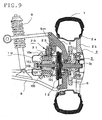
- the present invention is also applicable to modes of application where the wheel 2 is driven by the electric motor 10 only.
- a motor mounting member 5m may be provided on the upper arm 7 side of a knuckle 5, and the motor mounting member 5m and the motor case 10a are connected to each other by the shock absorbing member 20, and the output shaft 10b of the motor and the rotary shaft 3k of the wheel hub may be connected to each other by a power transmission mechanism, such as a flexible coupling 12.
- a power transmission mechanism such as a flexible coupling 12.
- the motor can be reliably floating-mounted with respect to the unsprung portion of a vehicle, and the shock absorbing mechanism can be made smaller in size and lighter in weight.
- an in-wheel motor system which excels not only in the ground contact performance and riding comfort of the vehicle running on a rough road, but also in the space efficiency.
Landscapes
- Engineering & Computer Science (AREA)
- Mechanical Engineering (AREA)
- Chemical & Material Sciences (AREA)
- Combustion & Propulsion (AREA)
- Transportation (AREA)
- General Engineering & Computer Science (AREA)
- Power Engineering (AREA)
- Arrangement Or Mounting Of Propulsion Units For Vehicles (AREA)
Abstract
An electric motor 10 and a reduction gear mechanism 11 are connected to each other by a flexible coupling 12, such as an Oldham' s coupling, which is a power transmission mechanism. Also, a casing 11c of the reduction gear mechanism 11 is integrally structured together with a knuckle 5, which is an unsprung part of a vehicle, or mounted to the knuckle 5. Further, a motor case 10a of the electric motor 10 is mounted to a motor mounting member 4m provided on the lower part of a strut 4 for suspending the knuckle 5 through the medium of a shock absorbing mechanism 20 equipped with a spring member 21, a damper, and two guide members 23 for guiding the operating direction of the spring member 21 and the damper. An in-wheel motor system thus structured allows the mass of the motor 10 to act as the mass of a dynamic damper and thus features not only improved ground contact performance and riding comfort of a vehicle running on a rough road but also superior space efficiency.
Description
- The present invention relates to an in-wheel motor system equipped with a wheel driving motor adjoining a wheel and, more particularly, to an in-wheel motor system so structured as to support the motor through the medium of a shock absorbing mechanism or a shock absorbing member with respect to the around-the-wheel parts of a vehicle.
- In recent years, in-wheel motor systems are increasingly introduced into motor-driven vehicles such as electric vehicles. Those in-wheel motor systems typically have an electric motor or a geared driving motor or the like, which integrally incorporates an electric motor and a planetary reducer within a motor case, adjoining a wheel.
Generally, however, with vehicles having suspension mechanisms such as springs around the wheels, the greater the so-called unsprung mass, which is the mass of unsprung parts such as wheels, knuckles and suspension arms, is, the worse the road holding performance of the vehicle will be due to variation in the road engaging force of the tire when the vehicle is running on an uneven road. And, conventionally, there has been a problem that equipping a vehicle with in-wheel motors increases the unsprung mass, thus causing a drop in the road holding performance because the above-mentioned driving motor is coupled to the part called an upright or knuckle, which is one of the parts around the wheel of a vehicle.
In contrast with that, much attention is drawn to in-wheel motor systems which have the in-wheel motor elastically supported by a shock absorbing mechanism or a shock absorbing member with respect to the around-the-wheel parts of a vehicle, such as a knuckle, thus having the motor "floating-mounted" with respect to the around-the-wheel parts. Such in-wheel motor systems, by having the motor itself act as the weight of a dynamic damper, feature markedly improved ground contact performance and riding comfort of a vehicle running on a rough road (For example, seeReferences 1 to 3).
Reference 1:WO 02/083446 Al
Reference2: Japanese Unexamined Patent Application Publication No.2005-126037
Reference 3: Japanese Unexamined Patent Application Publication No.2005-225486 -
FIG. 10 illustrates a structural example of an in-wheel motor system which is provided with a wheel support system having a conventional double wishbone suspension. In this in-wheel motor system, a motor case 50c for a geared motor (in-wheel motor) 50, which integrally incorporates an electric motor 50a and a planetary reducer 50b within the motor case 50c, is mounted at the top and the bottom to motor mounts 51a and 51b, which are each a rubber or spring member expandible and contractible in the vertical direction of the vehicle. Also, the motor mounts 51a and 51b and knuckles 52 are connected to upper and lower suspension arms 54a and 54b via ball joints 53a and 53b, so that themotor 50 is floating-mounted between the knuckles 52, which are an unsprung part as mentioned above, thus having themotor 50 act as a weight of a dynamic damper. Also, an output shaft 50j of the planetary reducer 50b is connected to awheel hub 57 mounted on a wheel disk 56a of awheel 56 via a constant-velocity joint 55, so that the drive force of themotor 50 can be steadily transmitted to thewheel 56. Note that in the figure the numeral 58 denotes a tire fitted to a rim 56b of thewheel 56 and numeral 59 a suspension member consisting of a shock absorber or the like mounted on the upper and lower suspension arms 54a and 54b. - In the aforementioned conventional in-wheel motor system, however, a planetary reducer 50b with large output torque and a
wheel 56 are coupled to each other by a constant-velocity joint 55, which is a power transmission mechanism. Hence, the large load torque of the power transmission mechanism presents a problem of durability.
Also, the characteristics of a motor, the reduction ratio of a reduction gear mechanism, and the like must be selected to meet the tire size, necessary torque and so on. However, in a conventional case as described above, an electric motor 51a and a planetary reducer 50b are integrally structured together, so that there is a problem of inability to replace the electric motor 51a and the planetary reducer 50b separately. - The present invention has been made in view of these conventional problems, and an object thereof is to provide an in-wheel motor system that not only excels in space efficiency but also provides a reliable "floating-mounting" of a motor with respect to the unsprung parts of a vehicle.
- According to a first aspect of the present invention, there is provided an in-wheel motor system comprising an electric motor and a reduction gear mechanism for reducing the rotation speed of an output shaft of the motor and transmitting the motive power of the motor to the wheel, wherein the motive power of the motor is transmitted to the wheel through the reduction gear mechanism, and wherein a motor case supporting the stator side of the motor is mounted on an unsprung part of a vehicle through the medium of a shock absorbing member or a shock absorbing mechanism and a casing of the reduction gear mechanism is integrally structured together with a knuckle which is coupled to a suspension mechanism of the vehicle.
According to a second aspect of the present invention, there is provided an in-wheel motor system, wherein the casing of the reduction gear mechanism and the motor case are structured as separate units.
According to a third aspect of the present invention, there is provided an in-wheel motor system, wherein the motor and the reduction gear mechanism are connected to each other by a flexible coupling.
According to a fourth aspect of the present invention, there is provided an in-wheel motor system, wherein a motor mounting member is disposed on a strut suspending the knuckle from a vehicle body and the shock absorbing member or shock absorbing mechanism is disposed between the motor mounting member and the upper face side of the motor case. - According to a fifth aspect of the present invention, there is provided an in-wheel motor system, wherein the reduction gear mechanism is constituted by a first reduction gear mechanism directly connected to an output shaft of the motor and a second reduction gear mechanism connecting the first reduction gear mechanism to the wheel.
According to a sixth aspect of the present invention, there is provided an in-wheel motor system, wherein a planetary gear mechanism is used as the reduction gear mechanism. - According to a seventh aspect of the present invention, there is provided an in-wheel motor system, wherein the upper face side of the motor case supporting the stator side of the motor is connected to a knuckle coupled to a wheel section by a shock absorbing mechanism equipped with a spring member and a damper and the spring member is disposed at the center of the motor case in the tire fore-aft direction on the upper face side thereof.
According to an eighth aspect of the present invention, there is provided an in-wheel motor system, wherein the shock absorbing mechanism is provided with a guide member for guiding the operating direction of the spring member and the damper and the spring member, the damper, and the guide member are disposed between the motor case and the motor mounting member.
According to a ninth aspect of the present invention, there is provided an in-wheel motor system, wherein the shock absorbing mechanism is provided with a guide member for guiding the operating direction of the spring member and the damper and the guide member is disposed in symmetrical positions with respect to the center of the spring member in the tire fore-aft direction on the upper face side of the motor case.
According to a tenth aspect of the present invention, there is provided an in-wheel motor system, wherein the drive force of the motor is transmitted to the wheel through the medium of a flexible coupling. - According to a eleventh aspect of the present invention, there is provided an in-wheel motor system incorporated into a drive wheel comprising an electric motor and a reduction gear mechanism connected to an output shaft of the electric motor for reducing the rotation speed of the motor and transmitting it to a wheel, wherein the motor and the reduction gear mechanism are connected to each other by a flexible coupling, and wherein a motor case supporting the stator side of the motor and an unsprung part of a vehicle are connected to each other by a shock absorbing mechanism equipped with a spring member and a damper, whereby the mass of the motor acts as the mass of a dynamic damper.
According to an twelfth aspect of the present invention, there is provided an in-wheel motor system, wherein a motor mounting member is disposed on a strut suspending the knuckle, which is an unsprung member of a vehicle, from a vehicle body and the motor case supporting the stator side of the motor is mounted to the motor mounting member through the medium of a shock absorbing mechanism, whereby the mass of the motor acts as the mass of a dynamic damper. - According to the present invention, the motive power of an electric motor is transmitted to a wheel through the medium of a reduction gear mechanism. And also the motor case supporting the stator side of the motor is floating-mounted with respect to the unsprung portion of a vehicle, with the motor case connected to a knuckle coupled to a wheel section or to a motor mounting member provided on a strut suspending a knuckle from a vehicle body by a shock absorbing member or a shock absorbing mechanism equipped with a spring member and a damper. As a result, the ground contact performance of the vehicle and the riding comfort can be both improved markedly. And if a casing of the reduction gear mechanism is integrally structured together with a knuckle coupled to the suspension mechanism of the vehicle, then it will be possible to replace the motor and the reduction gear mechanism separately. This makes it possible to use the same motor for wheels of different tire diameters or change the output torque by changing the reduction gear mechanism only.
Also, with the structure of the present invention employed, the motor only will be mounted on the unsprung portion of the vehicle, so that the durability of the power transmission mechanism, such as a flexible coupling, that couples the electric motor to the reduction gear mechanism can be improved.
Moreover, the reduction gear mechanism may be constituted by a first reduction gear mechanism connected directly to the output shaft of the motor and a second reduction gear mechanism connecting the first reduction gear mechanism to the wheel, and the rotation speed of the electric motor may be reduced in two stages and transmitted to the wheel. Then, even when a small motor of high rotation speed and low torque is used, a large drive force can be produced without the use of a reduction gear mechanism of a larger diameter.
Also, planetary gear mechanisms may be used as the first and second reduction gear mechanisms. Then, the motor shaft and the gear shaft are coaxial with each other, so that the diameter of the gear housing will never greatly exceed that of the motor housing, thus ensuring even higher space efficiency. - Also, the upper face side of the motor case and the knuckle coupled to a wheel section may be connected to each other by a shock absorbing mechanism equipped with a damper and a spring member and the spring member may be disposed on the upper face side of the motor case and at the center of the motor case in the tire fore-aft direction. Then the space efficiency may not only rise, but also the mass of the motor may act stably as the mass of a dynamic damper.
Moreover, the shock absorbing mechanism may be provided with a guide member for guiding the operating direction of the spring member and the damper, and the spring member, the damper and the guide member may be disposed not only between the motor case and the motor mounting member but also on the upper face side of the motor case and in symmetrical positions with respect to the center of the spring member in the tire fore-aft direction. Then the spring member and the damper can be guided reliably in the up-and-down direction, so that the mass of the motor may function sufficiently as the mass of a dynamic damper.
Note also that the motor is mounted on the knuckle through the medium of a shock absorbing mechanism. Therefore, if the drive force of the motor is transmitted to the wheel by connecting the motor to the wheel by a power transmission mechanism such as a universal joint or a flexible coupling, then the drive force of the motor can be transmitted to the wheel steadily. - Also, the electric motor, which is the source of drive, and the reduction gear mechanism, which transmits the rotation force of the motor to the wheel, may be connected to each other by a flexible coupling, and the motor case supporting the stator side of the motor may be connected to a knuckle coupled to a wheel section or to a motor mounting member provided on a strut suspending a knuckle from the vehicle body by means of a shock absorbing mechanism equipped with a spring member and a damper. This arrangement may separate the mass of the reduction gear mechanism from the mass of the motor, thereby allowing the mass of the motor alone to act as the mass of the dynamic damper. Then it will be possible not only to reduce the load working on the flexible coupling markedly but also to reduce the drive force (torque) to be inputted to the flexible coupling, which is the power transmission mechanism. Also, since the reduction gear mechanism driving the wheel is connected directly to the wheel hub, the drive efficiency can be improved markedly.
-
-
FIG. 1 is a vertical sectional view showing a structure of an in-wheel motor system according toEmbodiment 1. -
FIG. 2 is a perspective illustration showing a structure of an in-wheel motor system according toEmbodiment 1. -
FIG. 3 is an illustration showing an outline of a planetary gear mechanism. -
FIG. 4 is an illustration showing an outline of a parallel shaft gear mechanism. -
FIG. 5 is a vertical sectional view showing a structure of an in-wheel motor system according toEmbodiment 2. -
FIG. 6 is a perspective illustration showing a structure of an in-wheel motor system according toEmbodiment 2. -
FIG. 7 is an illustration showing another structure of an in-wheel motor system according to the present invention. -
FIG. 8 is an illustration showing still another structure of an in-wheel motor system according to the present invention. -
FIG. 9 is an illustration showing yet another structure of an in-wheel motor system according to the present invention. -
FIG. 10 is an illustration showing a structure of a conventional in-wheel motor system. -
- 1
- tire
- 2
- wheel
- 2a
- rim
- 2b
- wheel disk
- 3
- wheel hub
- 3k
- rotary shaft of wheel hub
- 4
- strut
- 4a
- coil spring
- 4b
- shock absorber
- 4m, 5m
- motor mounting member
- 5
- knuckle
- 5j
- bearing
- 6
- damping mechanism
- 7
- upper arm
- 8
- lower arm
- 10
- electric motor
- 10a
- motor case
- 10b
- output shaft
- 10j
- bearing
- 10S
- stator
- 10R
- rotor
- 11
- reduction gear mechanism
- 11a
- first planetary gear mechanism
- 11b
- second planetary gear mechanism
- 11c
- case
- 11k
- carrier
- 12
- flexible coupling
- 20
- shock absorbing mechanism
- 21
- spring member
- 22
- damper
- 22a
- cylinder
- 22b
- shaft
- 23A, 23B
- guide member
- 23a
- fixed part
- 23b
- guide shaft
- Preferred embodiments of the present invention will be described hereinbelow with reference to the accompanying drawings.
-
FIG. 1 is a vertical sectional view showing a structure of an in-wheel motor system according toEmbodiment 1, andFIG. 2 is a perspective illustration thereof. In each of the figures,reference numeral 1 denotes a tire, 2 a wheel composed of a rim 2a and a wheel disk 2b, 3 a wheel hub connected to thewheel 2 at the rotary shaft thereof, 4 a strut having a coil spring 4a and a shock absorber 4b and suspending aknuckle 5 connected thereto via thewheel hub 3 and abearing 5j from a vehicle body, 6 a brake mechanism mounted to thewheel hub strut 4, and 8 a lower arm supporting theknuckle 5 from below.
Also,reference numeral 10 denotes an electric motor provided with amotor case 10a supporting thestator 10S side thereof, anoutput shaft 10 rotatably mounted on themotor case 10a bybearings 10j, and arotor 10R mounted on theoutput shaft planetary gear mechanism 11a connected to theoutput shaft 10b of themotor 10 and a secondaryplanetary gear mechanism 11b connecting the firstplanetary gear mechanism 11a to thewheel hub 3 for reducing the rotation speed of themotor 10 and transmitting it to thewheel 2. - In this embodiment, the
electric motor 10 and thereduction gear mechanism 11 are placed in separate casings, and theelectric motor 10 and thereduction gear mechanism 11 are connected to each other by aflexible coupling 12, which is a power transmission mechanism such as an Oldham's coupling. Acasing 11c of thereduction gear mechanism 11 is integrally structured together with theknuckle 5, and by providing a motor mounting member 4m on the lower part of thestrut 4, themotor case 10a supporting thestator 10S side of themotor 10 is mounted to the motor mounting member 4m through the medium of ashock absorbing mechanism 20 to be described in detail below. Accordingly, removal of theflexible coupling 12 allows separation of theelectric motor 10 and thereduction gear mechanism 11 from each other, so that it becomes possible to replace themotor 10 and thereduction gear mechanism 11, which is integrated with theknuckle 5, separately. - More specifically, the
shock absorbing mechanism 20 includes aspring member 21 which is a coil spring, adamper 22 which has acylinder 22a, a not-shown piston, and ashaft 22b coupled with the piston, and two guide members 23 (23A and 23B) consisting of afixed part 23a and aguide shaft 23b for guiding the operation of thespring member 21 and thedamper 22 in an up-and-down direction. And one end of thespring member 21 is mounted to the motor mounting member 4m, and the other end thereof to the central portion of the upper face side (strut 4 side) of themotor case 10a. Also, thecylinder 22a of thedamper 22 is mounted to one side face of themotor case 10a, and one end of theshaft 22b to one end of the motor mounting member 4m.
Also, the twoguide members spring member 21 in the middle. That is, the fixedparts guide members guide shafts motor case 10a.
In this manner, the present embodiment uses an arrangement such that onespring member 21 is mounted to a central portion of the upper face side of themotor case 10a and two guide members 23A and 23B are disposed on both sides thereof, so that thespring member 21 can be guided steadily in the up-and-down direction. Thus, themotor 10 functions sufficiently as a dynamic damper, which not only improves markedly the ground contact performance and riding comfort of a vehicle running on a rough road, but also simplifies the structure of ashock absorbing mechanism 20. - Also, more specifically, the
planetary gear mechanism 11a (11b), as shown inFIGS. 3A and 3B , includes a sun gear 11p,planetary gears 11z which, connected to the sun gear 11p mounted to the input shaft by arms 11q, revolve around the shaft of the sun gear 11p through the space between the sun gear 11p and a ring gear 11r mounted to the inner surface of a not-shown gear housing, and acarrier 11k connected to theplanetary gears 11z and mounted to the output shaft. Theplanetary gear mechanism 11a (11b) is a mechanism for reducing the rotation speed of the sun gear 11p to a rotation speed which corresponds to the period of revolution of theplanetary gears 11z. And, in the present embodiment, thecarrier 11k of the secondplanetary gear mechanism 11b is coupled to arotary shaft 3k of awheel hub 3 by a spline coupling or a serration coupling, and thus the rotation of theelectric motor 10 is transmitted to thewheel 2.
It is to be noted that the reduction gear mechanism may also be a parallelshaft gear mechanism 70 as shown inFIG. 4 . However, for the parallelshaft gear mechanism 70, there need to be an output shaft J of the motor, acounter shaft 71, which is a shaft other than the former, and gears 72a and 72b. As a result, agear housing 11c may have a larger diameter, which presents the possibility of interference with peripheral members such as theknuckle 5. And this creates the problem of not only limited freedom of layout but also of the necessity to use a larger bearing at the shaft end because of a reaction force F arising from gear mesh.
In contrast with that, the present embodiment usesplanetary gear mechanisms
Also, in thereduction gear mechanism 11, the firstplanetary gear mechanism 11a and the secondplanetary gear mechanism 11b are connected to each other in series. That is, the input shaft of the firstplanetary gear mechanism 11a is connected to theoutput shaft 10b of theelectric motor 10, and thecarrier 11k of the firstplanetary gear mechanism 11a is connected to the input shaft of the secondplanetary gear mechanism 11b. Thus, the output torque of the firstplanetary gear mechanism 11a can be made larger at the secondplanetary gear mechanism 11b before it is transmitted to thewheel 2. As a result, even when a motor of low torque is used, the wheel can be driven adequately, and furthermore the rotation speed is reduced in two stages, so that the rotation speed of the motor can be raised. Therefore, it is possible that an adequate drive force can be produced even when theelectric motor 10 used is a small, light-weight motor of high rotation speed and low torque. - Generally speaking, where a rotary drive mechanism combining an
electric motor 10 and areduction gear mechanism 11 is used, it is possible to use a small motor of higher rotation speed and lower torque than those of a direct-drive motor driving awheel 2 directly. However, with a conventional in-wheel motor as shown inFIG. 10 , a planetary reducer 50b of large output torque is coupled to awheel 56 by a constant-velocity oint 55, which is a power transmission mechanism, and therefore the load torque of the power transmission mechanism is large. In contrast with that, aflexible coupling 12, which is the power transmission mechanism of the present embodiment, connects a smallelectric motor 10 of low torque to areduction gear mechanism 11. Therefore the load torque is small, and hence the durability of the power transmission mechanism can be improved. Moreover, since the output of thereduction gear mechanism 11 is transmitted directly to thewheel 2, the drive efficiency is improved over that of the conventional system.
Also, as in the present embodiment, the use of areduction gear mechanism 11, which is a twin arrangement of afirst gear mechanism 11a and asecond gear mechanism 11b connected in series, can make theelectric motor 10 even more small-size and light-weight. Therefore the load torque acting on the flexible coupling can be made smaller, and the durability thereof further improved. And in addition, when elastically supporting theelectric motor 10 separated from the mass of thereduction gear mechanism 11, it is sufficient to support themotor case 10a from above only, as stated above. This not only makes theshock absorbing mechanism 20 smaller and lighter-weight, but also improves the space efficiency. - As described hereinabove, according to
Embodiment 1, theelectric motor 10 and thereduction gear mechanism 11 are placed in separate casings, and theelectric motor 10 and thereduction gear mechanism 11 are connected to each other by aflexible coupling 12 such as an Oldham's coupling, which is a power transmission mechanism. A motor mounting member 4m is provided on the lower part of thestrut 4 and themotor case 10a supporting thestator 10S side of themotor 10 is mounted on the motor mounting member 4m through the medium ofshock absorbing mechanism 20. Also, acasing 11c of thereduction gear mechanism 11 is integrally structured together with theknuckle 5, so that the load torque can be made smaller, and the durability thereof can be improved. And it becomes possible to replace themotor 10 and thereduction gear mechanism 11, which is integrated with theknuckle 5, separately.
Also, a motor mounting member 4m is provided on the lower part of astrut 4 suspending theknuckle 5, and themotor 10 is mounted on the motor mounting member 4m through the medium of ashock absorbing mechanism 20 equipped with two guide members 23A and 23B for guiding the operating direction of aspring member 21 and adamper 22, thereby having only the mass of themotor 10 act as the mass of the dynamic damper. Thus, the ground contact performance and riding comfort of a vehicle running on a rough road are both improved markedly. - Also, a
reduction gear mechanism 11, which transmits the rotation of theelectric motor 10 to thewheel 2, is constituted by a firstplanetary gear mechanism 11a connected to theoutput shaft 10b of theelectric motor 10 and a secondplanetary gear mechanism 11b connecting the firstplanetary gear mechanism 11a to thewheel hub 3. And thereduction gear mechanism 11 and theelectric motor 10, which are integrally structured together, are mounted to theknuckle 5. As a result, a large output torque can be obtained even when a small motor of high rotation speed and low torque is used. Accordingly, even when the tire is of a small diameter, an adequate drive force can be secured without the use of a reduction gear mechanism of a larger diameter. - In
Embodiment 1, anelectric motor 10 and areduction gear mechanism 11 are placed in separate casings. And, by providing a motor mounting member 4m on the lower part of astrut 4, amotor case 10a supporting thestator 10S side of themotor 10 is mounted on the motor mounting member 4m through the medium of ashock absorbing mechanism 20. Also, acasing 11c of thereduction gear mechanism 11 is integrally structured together with aknuckle 5. InEmbodiment 2, however, as shown inFIG. 5 andFIG. 6 , anelectric motor 10 and areduction gear mechanism 11 may be coupled with each other by aflexible coupling 12, and amotor case 10a supporting thestator 10S side of themotor 10 may be mounted to the motor mounting member 4m through the medium of ashock absorbing mechanism 20. And also acasing 11c of thereduction gear mechanism 11 may be fixed to aknuckle 5.
In this embodiment, too, thereduction gear mechanism 11 is separated from theelectric motor 10 by theflexible coupling 12. Therefore, acarrier 11k connected to a not-shown ring gear of asecond gear mechanism 11b of thereduction gear mechanism 11 may be coupled to arotary shaft 3k of awheel hub 3 by a spline coupling or a serration coupling, and thus the rotation force of theelectric motor 10 can be transmitted to awheel 2 while making allowance for the axial movement of therotary shaft 3k.
Also, in a similar manner toEmbodiment 1, asingle spring member 21 of theshock absorbing mechanism 20 may be mounted to a central portion of the upper face side of themotor case 10a, and two guide members 23A and 23B are disposed on both sides thereof, so thatspring member 21 can be guided steadily in the up-and-down direction. Thus, themotor 10 is allowed to function sufficiently as a dynamic damper, and also the structure of theshock absorbing mechanism 20 can be simplified. - In the heretofore described Embodiments 1 and 2, the suspension used to suspend wheels from the vehicle body is of a strut type. However, the present invention is not limited to such a structure, but is also applicable to vehicles with suspensions of other structures such as double wishbone suspensions. For example, in the case of a double wishbone suspension, as shown in
FIG. 7 andFIG. 8 , amotor mounting member 5m may be provided in the vicinity of the connecting point of aknuckle 5 and anupper arm 7, and themotor mounting member 5m and amotor case 10a may be connected with each other by ashock absorbing member 20, or otherwise the arrangement may be such that the upper side of theknuckle 5 is so formed as to protrude in the direction of theelectric motor 10 and theshock absorbing member 20 is mounted to this protruding portion. Note that in this case, too, it is important for the two guide members 23A and 23B to be disposed symmetrically with respect to the center of the motor case 10c in the tire fore-aft direction. As a result, theelectric motor 10 can be stably floating-mounted with respect to theknuckle 5.
Also, in the foregoing embodiments, there is only onespring member 21, which is disposed in the middle of two guide members 23A and 23B. However, it is not necessary that there is only onespring member 21, and there may be a plurality ofspring members 21. When there are a plurality ofspring members 21, it is preferable that they are disposed in symmetrical positions with respect to the center of themotor case 10a in the tire fore-aft direction. Also, when there are a plurality ofspring members 21, the space efficiency can be improved by disposing two of thespring members 21 between thefixed parts motor case 10a around the periphery of theguide shafts
It is to be appreciated that in the present invention a light-weightelectric motor 10 only is suspended from astrut 4 or aknuckle 5, so that a single unit ofspring member 21 ordamper 22 suffices for the purpose thereof. Moreover, their being only one provides the advantage of fewer constituent parts and easier assembly. - Also, it is not necessary that the
reduction gear mechanism 11 is in a twin arrangement. For example, for tires, such as small tires, that do not require much output torque, a single reduction gear mechanism as shown inFIG. 7 andFIG. 8 may suffice. This is due to the fact that the mass of theelectric motor 10 and the mass of thereduction gear mechanism 11 are separated from each other by theflexible coupling 12. And therefore, with themotor case 10a supported by ashock absorbing mechanism 20 from above only, theelectric motor 10 can function sufficiently as a dynamic damper.
Also, in the foregoing embodiments, theelectric motor 10 and thereduction gear mechanism 11 are connected to each other by aflexible coupling 12. However, the power transmission mechanism connecting theelectric motor 10 and thereduction gear mechanism 11 is not limited to theflexible coupling 12, and other types of power transmission mechanisms, such as constant-velocity joints, may also be used as long as they can allow eccentricity and deflection angle that may exist between the output shaft of the motor and the input shaft of the reduction gear mechanism. - Also, in the foregoing Embodiments 1 and 2, examples cited are such that the upper side of the
motor case 10a of a geared motor consisting of anelectric motor 10 and areduction gear mechanism 11 is connected to aknuckle 5 or a motor mounting member 4m provided on the lower part of astrut 4 suspending aknuckle 5 from the vehicle body by ashock absorbing mechanism 20. However, as shown inFIG. 9 , the present invention is also applicable to modes of application where thewheel 2 is driven by theelectric motor 10 only. In such a case, amotor mounting member 5m may be provided on theupper arm 7 side of aknuckle 5, and themotor mounting member 5m and themotor case 10a are connected to each other by theshock absorbing member 20, and theoutput shaft 10b of the motor and therotary shaft 3k of the wheel hub may be connected to each other by a power transmission mechanism, such as aflexible coupling 12. It is to be noted thatFIG. 9 shows a case where the vehicle suspension is a double wishbone type, but it goes without saying that the present invention is applicable to the strut-type suspension as well. - As discussed herein, according to the present invention, the motor can be reliably floating-mounted with respect to the unsprung portion of a vehicle, and the shock absorbing mechanism can be made smaller in size and lighter in weight. As a result, an in-wheel motor system which excels not only in the ground contact performance and riding comfort of the vehicle running on a rough road, but also in the space efficiency.
Claims (12)
- An in-wheel motor system comprising:an electric motor; anda reduction gear mechanism for reducing the rotation speed of an output shaft of the motor and transmitting the motive power of the motor to the wheel;wherein the motive power of the motor is transmitted to the wheel through the reduction gear mechanism, and wherein a motor case supporting the stator side of the motor is mounted on an unsprung part of a vehicle through the medium of a shock absorbing member or a shock absorbing mechanism and a casing of the reduction gear mechanism is integrally structured together with a knuckle which is coupled to a suspension mechanism of the vehicle.
- The in-wheel motor system according to claim 1, wherein the casing of the reduction gear mechanism and the motor case are structured as separate units.
- The in-wheel motor system according to claim 1 or claim 2, wherein the motor and the reduction gear mechanism are connected to each other by a flexible coupling.
- The in-wheel motor system according to any of claims 1 to 3, wherein a motor mounting member is disposed on a strut suspending the knuckle from a vehicle body and the shock absorbing member or shock absorbing mechanism is disposed between the motor mounting member and the upper face side of the motor case.
- The in-wheel motor system according to any of claims 1 to 4, wherein the reduction gear mechanism is constituted by a first reduction gear mechanism directly connected to an output shaft of the motor and a second reduction gear mechanism connecting the first reduction gear mechanism to the wheel.
- The in-wheel motor system according to any of claims 1 to 5, wherein a planetary gear mechanism is used as the reduction gear mechanism.
- The in-wheel motor system according to any of claims 1 to 6, wherein the upper face side of the motor case is connected to a knuckle coupled to a wheel section by a shock absorbing mechanism equipped with a spring member and a damper and the spring member is disposed at the center of the motor case in the tire fore-aft direction on the upper face side thereof.
- The in-wheel motor system according to claim 7, wherein the shock absorbing mechanism is provided with a guide member for guiding the operating direction of the spring member and the damper and the spring member, the damper, and the guide member are disposed between the motor case and the motor mounting member.
- The in-wheel motor system according to claim 7 or claim 8, wherein the shock absorbing mechanism is provided with a guide member for guiding the operating direction of the spring member and the damper and the guide member is disposed in symmetrical positions with respect to the center of the spring member in the tire fore-aft direction on the upper face side of the motor case.
- The in-wheel motor system according to any of claims 7 to 9, wherein the drive force of the motor is transmitted to the wheel through the medium of a flexible coupling.
- An in-wheel motor system incorporated into a drive wheel comprising:an electric motor; anda reduction gear mechanism connected to an output shaft of the electric motor for reducing the rotation speed of the motor and transmitting the motive power of the motor to a wheel;wherein the motor and the reduction gear mechanism are connected to each other by a flexible coupling, and wherein a motor case supporting the stator side of the motor and an unsprung part of a vehicle are connected to each other by a shock absorbing mechanism equipped with a spring member and a damper, whereby the mass of the motor acts as the mass of a dynamic damper.
- The in-wheel motor system according to claim 11, wherein a motor mounting member is disposed on a strut suspending the knuckle, which is an unsprung member of a vehicle, from a vehicle body and the motor case supporting the stator side of the motor is mounted to the motor mounting member through the medium of a shock absorbing mechanism, whereby the mass of the motor acts as the mass of a dynamic damper.
Applications Claiming Priority (6)
| Application Number | Priority Date | Filing Date | Title |
|---|---|---|---|
| JP2005357927A JP2007161022A (en) | 2005-12-12 | 2005-12-12 | In-wheel motor system |
| JP2005362310A JP2007161168A (en) | 2005-12-15 | 2005-12-15 | In-wheel motor system |
| JP2005362702A JP2007161177A (en) | 2005-12-16 | 2005-12-16 | In-wheel motor system |
| JP2005364454A JP2007174725A (en) | 2005-12-19 | 2005-12-19 | In-wheel motor system |
| JP2005365882A JP2007168507A (en) | 2005-12-20 | 2005-12-20 | In-wheel motor system |
| PCT/JP2006/324675 WO2007069567A1 (en) | 2005-12-12 | 2006-12-11 | In-wheel motor system |
Publications (2)
| Publication Number | Publication Date |
|---|---|
| EP1961602A1 true EP1961602A1 (en) | 2008-08-27 |
| EP1961602A4 EP1961602A4 (en) | 2009-01-07 |
Family
ID=38162875
Family Applications (1)
| Application Number | Title | Priority Date | Filing Date |
|---|---|---|---|
| EP06834430A Withdrawn EP1961602A4 (en) | 2005-12-12 | 2006-12-11 | In-wheel motor system |
Country Status (2)
| Country | Link |
|---|---|
| EP (1) | EP1961602A4 (en) |
| WO (1) | WO2007069567A1 (en) |
Cited By (20)
| Publication number | Priority date | Publication date | Assignee | Title |
|---|---|---|---|---|
| FR2949393A1 (en) * | 2009-08-27 | 2011-03-04 | Peugeot Citroen Automobiles Sa | Suspension device for motorized drive unit assembly of motor vehicle, has spring and damper interposed between support and motorized drive unit assembly, such that assembly oscillates with spring and damper to form mass of cylinder |
| DE102010043298A1 (en) | 2010-11-03 | 2012-05-03 | Robert Bosch Gmbh | Wheel suspension for individual wheel drive of electrically driven vehicle, particularly for steered wheel, comprises suspension element or damping element which is coupled with wheel carrier |
| DE102011005623A1 (en) * | 2011-03-16 | 2012-09-20 | Zf Friedrichshafen Ag | Drive device for driving a wheel of a suspension strut axle for an electrically driven vehicle |
| DE102011005625A1 (en) | 2011-03-16 | 2012-09-20 | Zf Friedrichshafen Ag | Drive device for driving a wheel of a torsion beam axle for an electrically driven vehicle |
| DE102011005618A1 (en) | 2011-03-16 | 2012-09-20 | Zf Friedrichshafen Ag | Drive device for driving a wheel for an electrically driven vehicle |
| DE102011005621A1 (en) | 2011-03-16 | 2012-09-20 | Zf Friedrichshafen Ag | Drive device for driving a wheel of a suspension strut axle for an electrically driven vehicle |
| DE102011005624A1 (en) | 2011-03-16 | 2012-09-20 | Zf Friedrichshafen Ag | Drive device for driving wheel for electrically driven vehicle, comprises electric machine and two planetary gears connected in series in output side of electric machine in force flow direction in train operation |
| CN103552466A (en) * | 2013-11-14 | 2014-02-05 | 上海电机学院 | Wheel-side driving system |
| US9132723B2 (en) | 2011-03-16 | 2015-09-15 | Zf Friedrichshafen Ag | Drive device for driving a wheel for an electrically powered vehicle |
| US9340103B2 (en) | 2011-01-21 | 2016-05-17 | Ntn Corporation | In-wheel motor drive device |
| EP2782241A4 (en) * | 2011-11-18 | 2016-07-20 | Ntn Toyo Bearing Co Ltd | Motor control device for electric automobile |
| CN106464082A (en) * | 2014-07-18 | 2017-02-22 | 三菱重工压缩机有限公司 | Variable electric motor system and electrically powered device |
| US9705378B2 (en) | 2011-03-07 | 2017-07-11 | Ntn Corporation | Drive device for electric vehicle |
| US9735648B2 (en) | 2011-03-07 | 2017-08-15 | Ntn Corporation | Drive device for electric vehicle |
| US9914348B2 (en) | 2014-06-30 | 2018-03-13 | Nissan North America, Inc. | Electric drive motor assembly for a wheel |
| GB2555651A (en) * | 2016-11-08 | 2018-05-09 | Ricardo Uk Ltd | Electric vehicle with improved drive assembly |
| US10544862B2 (en) | 2015-09-04 | 2020-01-28 | Mitsubishi Heavy Industries Compressor Corporation | Starting method for variable speed accelerator and starting control device for variable speed accelerator |
| DE102018130021A1 (en) * | 2018-11-27 | 2020-05-28 | Bayerische Motoren Werke Aktiengesellschaft | Drive arrangement of a motor vehicle with an electric motor |
| US11025180B2 (en) | 2016-06-15 | 2021-06-01 | Mitsubishi Heavy Industries Compressor Corporation | Variable speed accelerator |
| DE102020117438A1 (en) | 2020-07-02 | 2022-01-05 | Dr. Ing. H.C. F. Porsche Aktiengesellschaft | Drive module |
Families Citing this family (5)
| Publication number | Priority date | Publication date | Assignee | Title |
|---|---|---|---|---|
| CN102582417B (en) * | 2012-02-24 | 2014-11-05 | 无锡永凯达齿轮有限公司 | Speed-reducing type wheel electric drive system of electric vehicle |
| CN103112313B (en) * | 2013-03-13 | 2015-05-20 | 上海中科深江电动车辆有限公司 | Wheel rim drive device |
| CN103832271A (en) * | 2014-02-27 | 2014-06-04 | 浙江工业大学之江学院工业研究院 | Independent drive independent steering mechanism of electric vehicle |
| JP6490376B2 (en) * | 2014-09-26 | 2019-03-27 | 株式会社村上商会 | Electric vehicle drive system |
| CN109927500A (en) * | 2019-04-24 | 2019-06-25 | 青岛钢铁侠科技有限公司 | The damping wheel of mobile robot |
Family Cites Families (12)
| Publication number | Priority date | Publication date | Assignee | Title |
|---|---|---|---|---|
| FR2679842A1 (en) * | 1991-07-29 | 1993-02-05 | Shm Management Services Ag | MOTOR BEARING MODULE, IN PARTICULAR FOR MOTOR VEHICLE. |
| FR2726230A1 (en) * | 1994-10-27 | 1996-05-03 | Peugeot | Automobile wheel unit incorporating hub-mounted driving motor |
| JP3772638B2 (en) * | 2000-05-09 | 2006-05-10 | 日産自動車株式会社 | Wheel-in motor vehicle motor mounting structure |
| ES2280523T3 (en) * | 2001-04-16 | 2007-09-16 | Kabushiki Kaisha Bridgestone | ENGINE MOUNT METHOD INCLUDED IN THE WHEEL AND SYSTEM WITH THE ENGINE INCORPORATED IN THE WHEEL. |
| JP4038116B2 (en) * | 2002-11-14 | 2008-01-23 | 本田技研工業株式会社 | Vehicle with electric motor |
| JP4225114B2 (en) * | 2003-05-14 | 2009-02-18 | トヨタ自動車株式会社 | Suspension device for electric vehicle |
| JP4239674B2 (en) * | 2003-05-15 | 2009-03-18 | トヨタ自動車株式会社 | Suspension device for electric vehicle |
| DE602004023387D1 (en) * | 2003-05-14 | 2009-11-12 | Toyota Motor Co Ltd | SUSPENSION SYSTEM FOR AN ELECTRIC MOTOR VEHICLE |
| JP4311139B2 (en) * | 2003-09-12 | 2009-08-12 | トヨタ自動車株式会社 | Wheel structure |
| JP4113506B2 (en) * | 2003-09-30 | 2008-07-09 | トヨタ自動車株式会社 | Wheel support device |
| JP4312078B2 (en) * | 2004-02-25 | 2009-08-12 | トヨタ自動車株式会社 | Electric wheel |
| JP4442315B2 (en) * | 2004-05-18 | 2010-03-31 | トヨタ自動車株式会社 | Electric wheel |
-
2006
- 2006-12-11 EP EP06834430A patent/EP1961602A4/en not_active Withdrawn
- 2006-12-11 WO PCT/JP2006/324675 patent/WO2007069567A1/en not_active Ceased
Cited By (27)
| Publication number | Priority date | Publication date | Assignee | Title |
|---|---|---|---|---|
| FR2949393A1 (en) * | 2009-08-27 | 2011-03-04 | Peugeot Citroen Automobiles Sa | Suspension device for motorized drive unit assembly of motor vehicle, has spring and damper interposed between support and motorized drive unit assembly, such that assembly oscillates with spring and damper to form mass of cylinder |
| DE102010043298A1 (en) | 2010-11-03 | 2012-05-03 | Robert Bosch Gmbh | Wheel suspension for individual wheel drive of electrically driven vehicle, particularly for steered wheel, comprises suspension element or damping element which is coupled with wheel carrier |
| US9340103B2 (en) | 2011-01-21 | 2016-05-17 | Ntn Corporation | In-wheel motor drive device |
| US9705378B2 (en) | 2011-03-07 | 2017-07-11 | Ntn Corporation | Drive device for electric vehicle |
| US9735648B2 (en) | 2011-03-07 | 2017-08-15 | Ntn Corporation | Drive device for electric vehicle |
| DE102011005625A1 (en) | 2011-03-16 | 2012-09-20 | Zf Friedrichshafen Ag | Drive device for driving a wheel of a torsion beam axle for an electrically driven vehicle |
| DE102011005624A1 (en) | 2011-03-16 | 2012-09-20 | Zf Friedrichshafen Ag | Drive device for driving wheel for electrically driven vehicle, comprises electric machine and two planetary gears connected in series in output side of electric machine in force flow direction in train operation |
| US9132723B2 (en) | 2011-03-16 | 2015-09-15 | Zf Friedrichshafen Ag | Drive device for driving a wheel for an electrically powered vehicle |
| DE102011005621A1 (en) | 2011-03-16 | 2012-09-20 | Zf Friedrichshafen Ag | Drive device for driving a wheel of a suspension strut axle for an electrically driven vehicle |
| DE102011005618A1 (en) | 2011-03-16 | 2012-09-20 | Zf Friedrichshafen Ag | Drive device for driving a wheel for an electrically driven vehicle |
| DE102011005623A1 (en) * | 2011-03-16 | 2012-09-20 | Zf Friedrichshafen Ag | Drive device for driving a wheel of a suspension strut axle for an electrically driven vehicle |
| EP2782241A4 (en) * | 2011-11-18 | 2016-07-20 | Ntn Toyo Bearing Co Ltd | Motor control device for electric automobile |
| CN103552466A (en) * | 2013-11-14 | 2014-02-05 | 上海电机学院 | Wheel-side driving system |
| US9914348B2 (en) | 2014-06-30 | 2018-03-13 | Nissan North America, Inc. | Electric drive motor assembly for a wheel |
| CN106537734A (en) * | 2014-07-18 | 2017-03-22 | 三菱重工压缩机有限公司 | Rotary driving force imparting device and its electric device |
| EP3142230A4 (en) * | 2014-07-18 | 2017-11-01 | Mitsubishi Heavy Industries Compressor Corporation | Variable electric motor system and electrically powered device thereof |
| EP3171490A4 (en) * | 2014-07-18 | 2017-11-15 | Mitsubishi Heavy Industries Compressor Corporation | Variable electric motor system and electrically powered device |
| CN106464082A (en) * | 2014-07-18 | 2017-02-22 | 三菱重工压缩机有限公司 | Variable electric motor system and electrically powered device |
| US10177692B2 (en) | 2014-07-18 | 2019-01-08 | Mitsubishi Heavy Industries Compressor Corporation | Variable electric motor system and electrically powered device |
| CN106464082B (en) * | 2014-07-18 | 2019-03-29 | 三菱重工压缩机有限公司 | Variable Motor System |
| US10454394B2 (en) | 2014-07-18 | 2019-10-22 | Mitsubishi Heavy Industries Compressor Corporation | Rotational driving force imparting device and electric motor device for the same |
| US10601347B2 (en) | 2014-07-18 | 2020-03-24 | Mitsubishi Heavy Industries Compressor Corporation | Variable electric motor system and electrically powered device thereof |
| US10544862B2 (en) | 2015-09-04 | 2020-01-28 | Mitsubishi Heavy Industries Compressor Corporation | Starting method for variable speed accelerator and starting control device for variable speed accelerator |
| US11025180B2 (en) | 2016-06-15 | 2021-06-01 | Mitsubishi Heavy Industries Compressor Corporation | Variable speed accelerator |
| GB2555651A (en) * | 2016-11-08 | 2018-05-09 | Ricardo Uk Ltd | Electric vehicle with improved drive assembly |
| DE102018130021A1 (en) * | 2018-11-27 | 2020-05-28 | Bayerische Motoren Werke Aktiengesellschaft | Drive arrangement of a motor vehicle with an electric motor |
| DE102020117438A1 (en) | 2020-07-02 | 2022-01-05 | Dr. Ing. H.C. F. Porsche Aktiengesellschaft | Drive module |
Also Published As
| Publication number | Publication date |
|---|---|
| WO2007069567A1 (en) | 2007-06-21 |
| EP1961602A4 (en) | 2009-01-07 |
Similar Documents
| Publication | Publication Date | Title |
|---|---|---|
| US20090133944A1 (en) | In-wheel motor system | |
| EP1961602A1 (en) | In-wheel motor system | |
| EP1977924A1 (en) | In-wheel motor system | |
| JP4133186B2 (en) | In-wheel motor system for steering wheels | |
| US7641010B2 (en) | In-wheel motor with high durability | |
| US9108496B2 (en) | In-wheel motor drive assembly | |
| JP4113506B2 (en) | Wheel support device | |
| CN1950232B (en) | Vehicles equipped with in-wheel motors | |
| US8403794B2 (en) | Decelerator | |
| JP5133572B2 (en) | Mounting method and mounting structure of dynamic vibration absorber and in-wheel motor | |
| JP4694148B2 (en) | Motor parts | |
| JP2001001774A (en) | Axle structure of electric vehicle | |
| JP2004084939A (en) | Central bearing tuning absorber | |
| JP4312078B2 (en) | Electric wheel | |
| JP2007174725A (en) | In-wheel motor system | |
| JP2007283987A (en) | In-wheel motor system | |
| JP5736069B2 (en) | In-wheel motor drive device | |
| JP2007168507A (en) | In-wheel motor system | |
| JP2005238935A (en) | Wheel support device | |
| JP2007191027A (en) | In-wheel motor system | |
| JP2007161168A (en) | In-wheel motor system | |
| JP2007161177A (en) | In-wheel motor system | |
| JP2007168481A (en) | Dynamic vibration absorbing device for electric car | |
| JP5523860B2 (en) | In-wheel motor drive device |
Legal Events
| Date | Code | Title | Description |
|---|---|---|---|
| PUAI | Public reference made under article 153(3) epc to a published international application that has entered the european phase |
Free format text: ORIGINAL CODE: 0009012 |
|
| 17P | Request for examination filed |
Effective date: 20080610 |
|
| AK | Designated contracting states |
Kind code of ref document: A1 Designated state(s): DE FR GB IT |
|
| A4 | Supplementary search report drawn up and despatched |
Effective date: 20081204 |
|
| DAX | Request for extension of the european patent (deleted) | ||
| RBV | Designated contracting states (corrected) |
Designated state(s): DE FR GB IT |
|
| 17Q | First examination report despatched |
Effective date: 20090416 |
|
| STAA | Information on the status of an ep patent application or granted ep patent |
Free format text: STATUS: THE APPLICATION IS DEEMED TO BE WITHDRAWN |
|
| 18D | Application deemed to be withdrawn |
Effective date: 20120210 |