JP3772638B2 - Wheel-in motor vehicle motor mounting structure - Google Patents
Wheel-in motor vehicle motor mounting structure Download PDFInfo
- Publication number
- JP3772638B2 JP3772638B2 JP2000136156A JP2000136156A JP3772638B2 JP 3772638 B2 JP3772638 B2 JP 3772638B2 JP 2000136156 A JP2000136156 A JP 2000136156A JP 2000136156 A JP2000136156 A JP 2000136156A JP 3772638 B2 JP3772638 B2 JP 3772638B2
- Authority
- JP
- Japan
- Prior art keywords
- motor
- wheel
- axle
- center
- virtual kingpin
- Prior art date
- Legal status (The legal status is an assumption and is not a legal conclusion. Google has not performed a legal analysis and makes no representation as to the accuracy of the status listed.)
- Expired - Fee Related
Links
Images
Classifications
-
- B—PERFORMING OPERATIONS; TRANSPORTING
- B60—VEHICLES IN GENERAL
- B60G—VEHICLE SUSPENSION ARRANGEMENTS
- B60G2200/00—Indexing codes relating to suspension types
- B60G2200/10—Independent suspensions
- B60G2200/14—Independent suspensions with lateral arms
- B60G2200/142—Independent suspensions with lateral arms with a single lateral arm, e.g. MacPherson type
-
- B—PERFORMING OPERATIONS; TRANSPORTING
- B60—VEHICLES IN GENERAL
- B60G—VEHICLE SUSPENSION ARRANGEMENTS
- B60G2200/00—Indexing codes relating to suspension types
- B60G2200/40—Indexing codes relating to the wheels in the suspensions
- B60G2200/422—Driving wheels or live axles
-
- B—PERFORMING OPERATIONS; TRANSPORTING
- B60—VEHICLES IN GENERAL
- B60G—VEHICLE SUSPENSION ARRANGEMENTS
- B60G2204/00—Indexing codes related to suspensions per se or to auxiliary parts
- B60G2204/10—Mounting of suspension elements
- B60G2204/12—Mounting of springs or dampers
- B60G2204/129—Damper mount on wheel suspension or knuckle
-
- B—PERFORMING OPERATIONS; TRANSPORTING
- B60—VEHICLES IN GENERAL
- B60G—VEHICLE SUSPENSION ARRANGEMENTS
- B60G2300/00—Indexing codes relating to the type of vehicle
- B60G2300/50—Electric vehicles; Hybrid vehicles
Landscapes
- Axle Suspensions And Sidecars For Cycles (AREA)
- Arrangement Or Mounting Of Propulsion Units For Vehicles (AREA)
- Vehicle Body Suspensions (AREA)
Description
【0001】
【発明の属する技術分野】
この発明は、車輪を回転可能に支持するアクスルに取り付けられて車輪を駆動するモータを備えたホイールインモータ車のモータ搭載構造に関する。
【0002】
【従来の技術】
従来、ホイールインモータ車のモータ搭載構造としては、例えば特開平5−116545号公報に記載されたものがある。これは、仮想キングピン軸と路面との交点と、タイヤ幅方向の中心線と路面との交点との距離、すなわちスクラブ半径が大きいことにより生じる操舵力の増大を、前記スクラブ半径を小さくして低減しようとするものである。
【0003】
【発明が解決しようとする課題】
しかしながら、上記した従来のホイールインモータ車のモータ搭載構造にあっては、仮想キングピン軸に対し、タイヤやロードホイール、さらにはアクスル・ブレーキ部品が車両外側に大きくオフセットしており、その結果操舵時における仮想キングピン軸廻りの慣性重量が大きく、操舵に違和感(操舵力が重い)を感じることがある。これを解決をする手段としては、例えば油圧式パワーステアリングのポンプ能力アップによる方法があるが、エンジン負荷が大きくなり燃費が悪化するという問題がある。
【0004】
そこで、この発明は、燃費の悪化を招くことなく、仮想キングピン軸廻りの慣性重量を小さくして操舵力の増大を防止することを目的としている。
【0005】
【課題を解決するための手段】
前記目的を達成するために、請求項1の発明は、車輪を回転可能に支持するアクスルに取り付けられて前記車輪を駆動するモータを備え、前記アクスルと車体との間に取り付けられて軸線方向に伸縮可能なショックアブソーバの車体側取付部と、前記モータの下方にて、アクスルと車体との間を連結するサスペンションリンクのアクスル側取付部とを結ぶ仮想キングピン軸を中心として操舵時に回転する回転部分の重心を、前記仮想キングピン軸上に配置した構成としてある。
【0006】
このような構成のホイールインモータ車のモータ搭載構造によれば、操舵時には、仮想キングピン軸を中心として回転する回転部分は、その重心が仮想キングピン軸上に位置した状態で回転する。
【0007】
請求項2の発明は、請求項1の発明の構成において、車輪、アクスルおよびモータの3部品合わせた重心を、仮想キングピン軸上に配置した構成としてある。
【0008】
上記構成によれば、操舵時には、仮想キングピン軸を中心として回転する車輪、アクスルおよびモータを合わせた3部品は、その3部品合わせた重心が仮想キングピン軸上に位置した状態で回転する。
【0009】
請求項3の発明は、請求項1の発明の構成において、モータの重心を、仮想キングピン軸上に配置した構成としてある。
【0010】
上記構成によれば、操舵時には、仮想キングピン軸を中心として回転するモータは、その重心が仮想キングピン軸上に位置した状態で回転する。
【0011】
請求項4の発明は、請求項1の発明の構成において、モータとアクスルとの間に、モータの回転を減速して伝達する減速機を配置し、車輪、アクスル、モータおよび減速機の4部品合わせた重心を、仮想キングピン軸上に配置した構成としてある。
【0012】
上記構成によれば、操舵時には、仮想キングピン軸を中心として回転する車輪、アクスル、モータおよび減速機は、その4部品合わせた重心が仮想キングピン軸上に位置した状態で回転する。
【0013】
請求項5の発明は、請求項1の発明の構成において、モータとアクスルとの間に、モータの回転を減速して伝達する減速機を配置し、モータおよび減速機の2部品合わせた重心を、仮想キングピン軸上に配置した構成としてある。
【0014】
上記構成によれば、操舵時には、仮想キングピン軸を中心として回転するモータおよび減速機は、その2部品合わせた重心が仮想キングピン軸上に位置した状態で回転する。
【0015】
請求項6の発明は、請求項4または5の発明の構成において、減速機は、サンギアおよびプラネタリギアを備えた遊星歯車機構で構成され、この遊星歯車機構の出力軸と同軸回転する出力ギアに噛み合う駆動ギアを、前記出力ギアの下方位置にて車輪の回転中心軸に同軸回転可能に設けた構成としてある。
【0016】
上記構成によれば、車輪の回転中心軸と同軸の駆動ギアの上方に、遊星歯車機構およびモータが配置され、モータ下方の空間が大きくなる。
【0017】
【発明の効果】
請求項1の発明によれば、操舵時に仮想キングピン軸を中心として回転する回転部分は、その重心が仮想キングピン軸上に配置されているので、エンジン負荷の増大による燃費悪化を招くことなく、仮想キングピン軸廻りの慣性重量が軽減し、操舵力を小さくすることができる。
【0018】
請求項2の発明によれば、車輪、アクスルおよびモータの3部品合わせた重心を、仮想キングピン軸上に配置したので、操舵時に仮想キングピン軸を中心として回転する車輪、アクスルおよびモータは、その3部品合わせた重心が仮想キングピン軸上に位置した状態で回転し、仮想キングピン軸廻りの慣性重量を軽減させることができる。
【0019】
請求項3の発明によれば、モータの重心を、仮想キングピン軸上に配置したので、操舵時に仮想キングピン軸を中心として回転するモータは、その重心が仮想キングピン軸上に位置した状態で回転し、仮想キングピン軸廻りの慣性重量を軽減させることができる。
【0020】
請求項4の発明によれば、モータとアクスルとの間に、モータの回転を減速して伝達する減速機を配置し、車輪、アクスル、モータおよび減速機の4部品合わせた重心を、仮想キングピン軸上に配置したので、操舵時に仮想キングピン軸を中心として回転する車輪、アクスル、モータおよび減速機は、その4部品合わせた重心が仮想キングピン軸上に位置した状態で回転し、仮想キングピン軸廻りの慣性重量を軽減させることができる。
【0021】
請求項5の発明によれば、モータとアクスルとの間に、モータの回転を減速して伝達する減速機を配置し、モータおよび減速機の2部品合わせた重心を、仮想キングピン軸上に配置したので、操舵時に仮想キングピン軸を中心として回転するモータおよび減速機は、その2部品合わせた重心が仮想キングピン軸上に位置した状態で回転し、仮想キングピン軸廻りの慣性重量を軽減することができる。
【0022】
請求項6の発明によれば、減速機は、サンギアおよびプラネタリギアを備えた遊星歯車機構であり、この遊星歯車機構の出力軸と同軸回転する出力ギアに噛み合う駆動ギアを、前記出力ギアの下方位置にて車輪の回転中心軸に対して同軸回転可能に設けたので、車輪の回転中心軸と同軸の駆動ギアの上方に、遊星歯車機構およびモータが配置されてモータの下方空間が大きくなり、モータの設計自由度が大きくなる。
【0023】
【発明の実施の形態】
以下、この発明の実施の形態を図面に基づき説明する。
【0024】
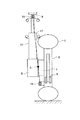
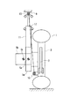
図1は、この発明の実施の一形態を示すホイールインモータ車のモータ搭載構造の基本構造図である。車両前部の車輪1を回転可能に支持するアクスル3にはブレーキ4が設けられるとともに、車輪1を回転駆動するモータ5が、駆動力を減速して車輪1に伝える減速機7を介して装着されている。
【0025】
モータ5と車体9との間には、ショックアブソーバ11が配置されている。ショックアブソーバ11の車体9に対する車体側取付部となるアッパマウント13と、アクスル3に取り付けられているアクスル側取付部となるロワボールジョイント15とを結ぶ符号17で示すものは、サスペンション仮想キングピン軸(以下、単に仮想キングピン軸と呼ぶ)である。
【0026】
上記したサスペンション仮想キングピン軸17上に、操舵時の回転部分の重心がある場合には、慣性モーメントは零であるが、前記重心が仮想キングピン軸17からオフセットされていると、操舵時に慣性モーメントが発生し、ステアリング操舵力が大きくなって、ドライバに違和感を与える。
【0027】
上記した回転部分としては、車輪1、アクスル3、モータ5、減速機7およびショックアブソーバ11であり、ここでは、これらの5つの部品を合わせた部品の重心Gを、仮想キングピン軸17上に設定してある。これにより、ステアリングを操舵するときの仮想キングピン軸17廻りのトータルの慣性モーメント増加が防止され、操舵力が低減し、操舵フィーリングが良好となる。これはパワーステアリングのポンプ能力をアップさせる必要がなく、したがってエンジン負荷の増大による燃費悪化も発生しない。
【0028】
なお、上記実施の形態では、回転部分として車輪1、アクスル3、モータ5、減速機7およびショックアブソーバ11の5つの部品すべてを、考慮したが、いずれか1つあるいは複数の部品を組み合わせた部品全体の重心を、仮想キングピン軸17上に設定しても、パワーステアリングのポンプ能力をアップさせることなく、仮想キングピン軸17廻りのトータルの慣性モーメント増加が防止される。このように、回転部分として重心位置を考慮する部品数を少なくすることで、設計が容易となる。
【0029】
例えば、モータ5のみの重心を、仮想キングピン軸17上に設定してもよく、また車輪1、アクスル3およびモータ5の3部品合わせた全体の重心を、仮想キングピン軸17上に設定してもよく、さらにモータ5および減速機7の2部品合わせた全体の重心を、仮想キングピン軸17上に設定してもよい。
【0030】
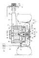
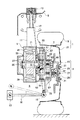
図2は、図1の詳細構造を示している。車輪1としてタイヤ19がロードホイール21に装着され、アクスル3は、ブレーキディスク23、ハブ25、スピンドル27、アクスルベアリング29とから構成されている。ブレーキディスク23とハブ25はボルト・ナット31によりロードホイール21に固定され、スピンドル27はナット32よりハブ25に固定されている。
【0031】
モータ5は、ロータ33が固定されたモータシャフト35が、一対のモータベアリング37を介してモータハウジング39に回転可能に設けられるとともに、モータハウジング39の内面にステータ41が装着されている。また、モータシャフト35の図中で左端部のモータハウジング39の外部には、モータ5の回転数を検出する回転数センサ43が設けられている。
【0032】
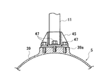
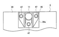
上端が車体9に連結されているショックアブソーバ11の下端は、図2のA−A断面図である図3および図3の平面図である図4に示すように、ショックアブソーバ11の下部に設けられている取付ブラケット45が、ボルト47によりモータハウジング39の厚肉部39aに締結されて、モータハウジング39に固定されている。
【0033】
なお、上記図3においては、内部のステータ41などは省略してあり、また、図2においては、図3における取付ブラケット45や厚肉部39aを省略してある。
【0034】
減速機7は、モータハウジング39の図中で右側に突出した部分のモータシャフト35に固定されたサンギヤ49と、サンギヤ49に噛み合う複数のプラネタリギア51とを備えた遊星歯車機構で構成され、これらが減速機ハウジング53内に収容されている。減速機ハウジング53は、内周面に、複数のプラネタリギア51が噛み合うリングギア55が装着され、図示しないボルトによりモータハウジング39に固定されている。複数のプラネタリギア51相互を連結するキャリア57は、前記したスピンドル27に連結され、減速機7からの回転動力がアクスル3および車輪1に伝達される。
【0035】
上記したモータハウジング39と減速機ハウジング53とは互いに別体で構成してあり、このため例えば放熱性が要求されるモータハウジング39をアルミ材で構成する一方、強度が要求される減速機ハウジング53を鉄で構成するなどで、最適設計が可能となる。
【0036】
ここでのロワボールジョイント15は、モータハウジング39の減速機7側の下部に突出している取付部59に回転可能に取り付けられ、ロワボールジョイント15に一端が連結されているサスペンションリンクとしてのロワリンク61の他端は、車体13側に回転可能に連結されている。
【0037】
アッパマウント13とロワボールジョイント15とを結ぶ直線は、仮想キングピン軸17であり、この仮想キングピン軸17を回転軸としてタイヤ19が操舵される。
【0038】
次に、仮想キングピン軸17に回転部分の重心Gを設定する方法を説明する。
【0039】
回転部分を構成する各部品、例えばショックアブソーバ11は、その車両の重量や要求性能に応じて設計されるものであるため、最適設計を行えばその大きさは必然的に決まる。モータ5、減速機7、アクスル3および車輪1なども同様である。
【0040】
ところで、モータ5の設計において、出力:Pとモータ直径:φDおよびモータ長さ(幅):Lとの間には、次式のような関係がある。
【0041】
P∝DXL
つまり、モータ出力(P)は、モータ直径:φDとモータ長さ:Lとの積に比例する。
【0042】
この関係を用いれば、同一出力のモータであっても、小径で長いモータあるいは、大径で短いモータが設計可能である。このことは、モータの設計方法によって同一出力のモータであっても、モータ5の重心位置が可変であることを意味している。
【0043】
図5に、モータ形状による重心位置の変更例を示す。これによれば、仮想キングピン軸17廻りの回転部分の重心Gが、仮想キングピン軸17に対して車両の内側(図5中で左側)にある場合には、大径で短い形状のモータ5a(モータの重心位置Ga)とすれば、重心Gaが車両外側に変更されて仮想キングピン軸17により近い位置に設定される。一方、仮想キングピン軸17廻りの回転部分の重心Gが、仮想キングピン軸17に対して車両の外側(図5中で右側)にある場合には、小径で長い形状のモータ5b(モータの重心位置Gb)とすれば、重心Gaが車両内側に変更されて仮想キングピン軸17により近い位置に設定される。
【0044】
なお、ショックアブソーバ11の構成部品であるストラットは、モータ5の形状に応じて長さを変更して対応する。
【0045】
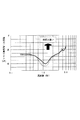
図6は、操舵力の周波数応答実験結果のデータを、ホイールインモータを搭載した車両(実線)とホイールインモータを搭載していない車両とで比較して示している。ホイールインモータ搭載車は、回転部分の重心が仮想キングピン軸に対してオフセットした(仮想キングピン軸に対して回転部分の重心位置が一致していない)場合である。
【0046】
これによれば、ホイールインモータ搭載車は、特に1Hz近辺でホイールインモータを搭載していない車両に対し、操舵力が大きくなっており、これが操舵感を悪化させている。すなわち、仮想キングピン軸17に対し回転部分の重心位置を一致させれば、操舵力の増加が回避されることを意味している。
【0047】
図7は、この発明の他の実施の形態を示している。この実施の形態は、減速機7における遊星歯車機構の出力軸63に、出力ギア65を取り付けるとともに、出力ギア65に噛み合う駆動ギア67を、車輪1の回転中心軸となるスピンドル27に出力ギア65の下方位置にて取り付けて、減速機7を構成している。また、出力軸63のキャリア57との連結側と反対側を、ベアリング69により減速機ハウジング53に回転可能に支持させるとともに、キャリア57をプラネタリギア51の両側に配置し、左側のキャリア57をベアリング71を介してモータハウジング39に回転可能に支持させている。
【0048】
ロワリンク61のロワボールジョイント15は、減速機ハウジング53の下部に設けた取付ブラケット73に取り付けられている。
【0049】
上記した図7の実施の形態においては、図2の実施の形態に対し、モータ5および遊星歯車機構を車体のより上方に配置できるので、モータ5とロワリンク61との空間Sを大きくとれ、このため、モータ5の設計自由度(重心Gの設定自由度)が大きくなる。
【0050】
図7において、ロワリンク61は、ショックアブソーバ11がノーマルな状態を実線で、バウンドした状態を二点鎖線で示しており、バウンド状態であっても、モータ5はロワリンク61との間に比較的大きなクリアランスが得られていることがわかる。
【0051】
なお、上記各実施の形態では、モータ5の構造を電動モータで説明したが、油圧モータで構成しても同様の効果が得られる。また、上記各実施の形態では、ショックアブソーバ11をストラット形式で説明したが、キングピン軸(仮想キングピン軸を含む)を有するものであれば、他の形式であっても構わない。
【図面の簡単な説明】
【図1】この発明の実施の一形態を示すホイールインモータ車のモータ搭載構造の基本構造図である。
【図2】図1の詳細構造図である。
【図3】図2のA−A断面図である。
【図4】図3の平面図である。
【図5】モータ形状による重心位置の変更例を示す説明図である。
【図6】操舵力の周波数応答実験結果のデータを、ホイールインモータを搭載した車両とホイールインモータを搭載していない車両とで比較して示した説明図ある。
【図7】この発明の他の実施の形態を示す詳細構造図である。
【符号の説明】
1 車輪(回転部分)
3 アクスル(回転部分)
5 ホイールインモータ(回転部分)
7 減速機(回転部分)
9 車体
11 ショックアブソーバ
13 アッパマウント(車体側取付部)
15 ロワボールジョイント(アクスル側取付部)
17 サスペンション仮想キングピン軸(仮想キングピン軸)
27 スピンドル(車輪の回転中心軸)
49 サンギア
51 プラネタリギア
61 ロワリンク(サスペンションリンク)
63 出力軸
65 出力ギア
67 駆動ギア[0001]
BACKGROUND OF THE INVENTION
The present invention relates to a motor mounting structure of a wheel-in motor vehicle that includes a motor that is attached to an axle that rotatably supports a wheel and drives the wheel.
[0002]
[Prior art]
Conventionally, as a motor mounting structure of a wheel-in motor vehicle, for example, there is one described in Japanese Patent Laid-Open No. 5-116545. This reduces the distance between the intersection of the virtual kingpin axis and the road surface and the intersection of the center line in the tire width direction and the road surface, that is, an increase in steering force caused by a large scrub radius by reducing the scrub radius. It is something to try.
[0003]
[Problems to be solved by the invention]
However, in the motor-mounted structure of the conventional wheel-in motor vehicle described above, the tire, road wheel, and axle / brake parts are largely offset from the virtual kingpin shaft to the outside of the vehicle. The inertia weight around the imaginary kingpin axis is large, and there may be a sense of discomfort (heavy steering force) in steering. As a means for solving this, there is a method of increasing the pumping capacity of hydraulic power steering, for example, but there is a problem that the engine load increases and the fuel consumption deteriorates.
[0004]
Accordingly, an object of the present invention is to prevent an increase in steering force by reducing the inertia weight around the virtual kingpin axis without causing deterioration of fuel consumption.
[0005]
[Means for Solving the Problems]
In order to achieve the object, the invention of
[0006]
According to the motor-mounted structure of the wheel-in motor vehicle having such a configuration, at the time of steering, the rotating portion that rotates about the virtual kingpin axis rotates with its center of gravity positioned on the virtual kingpin axis.
[0007]
According to a second aspect of the present invention, in the configuration of the first aspect of the invention, the center of gravity of the three components of the wheel, the axle and the motor is arranged on the virtual kingpin shaft.
[0008]
According to the above configuration, at the time of steering, the three parts including the wheel, the axle, and the motor that rotate about the virtual kingpin axis rotate in a state where the center of gravity of the three parts is located on the virtual kingpin axis.
[0009]
According to a third aspect of the present invention, in the configuration of the first aspect of the present invention, the center of gravity of the motor is arranged on a virtual kingpin shaft.
[0010]
According to the above configuration, at the time of steering, the motor that rotates about the virtual kingpin axis rotates with its center of gravity positioned on the virtual kingpin axis.
[0011]
According to a fourth aspect of the present invention, in the configuration of the first aspect of the present invention, a speed reducer that decelerates and transmits the rotation of the motor is disposed between the motor and the axle, and the four parts of the wheel, the axle, the motor, and the speed reducer. The combined center of gravity is arranged on the virtual kingpin axis.
[0012]
According to the above configuration, at the time of steering, the wheel, axle, motor, and speed reducer that rotate around the virtual kingpin axis rotate with the center of gravity of the four components positioned on the virtual kingpin axis.
[0013]
According to a fifth aspect of the present invention, in the configuration of the first aspect of the present invention, a reduction gear that reduces and transmits the rotation of the motor is arranged between the motor and the axle, and the center of gravity of the two parts of the motor and the reduction gear is combined. The configuration is arranged on a virtual kingpin axis.
[0014]
According to the above configuration, at the time of steering, the motor and the speed reducer that rotate about the virtual kingpin axis rotate with the center of gravity of the two components positioned on the virtual kingpin axis.
[0015]
According to a sixth aspect of the present invention, in the configuration of the fourth or fifth aspect of the present invention, the speed reducer includes a planetary gear mechanism including a sun gear and a planetary gear, and the output gear rotates coaxially with the output shaft of the planetary gear mechanism. The meshing drive gear is provided so as to be rotatable coaxially with the rotation center axis of the wheel at a position below the output gear.
[0016]
According to the above configuration, the planetary gear mechanism and the motor are disposed above the drive gear coaxial with the rotation center axis of the wheel, and the space below the motor is increased.
[0017]
【The invention's effect】
According to the first aspect of the present invention, since the center of gravity of the rotating portion that rotates around the virtual kingpin axis at the time of steering is arranged on the virtual kingpin axis, the fuel consumption does not deteriorate due to an increase in engine load. The inertia weight around the kingpin shaft is reduced and the steering force can be reduced.
[0018]
According to the invention of claim 2, since the center of gravity of the three components of the wheel, axle and motor is arranged on the virtual kingpin axis, the wheel, axle and motor rotating around the virtual kingpin axis during steering are It rotates with the center of gravity combined with the parts positioned on the virtual kingpin axis, and the inertia weight around the virtual kingpin axis can be reduced.
[0019]
According to the invention of
[0020]
According to the invention of
[0021]
According to the invention of
[0022]
According to the invention of claim 6, the speed reducer is a planetary gear mechanism including a sun gear and a planetary gear, and a drive gear meshing with an output gear that rotates coaxially with the output shaft of the planetary gear mechanism is provided below the output gear. Since it is provided coaxially with respect to the rotation center axis of the wheel at the position, the planetary gear mechanism and the motor are arranged above the drive gear coaxial with the rotation center axis of the wheel, and the lower space of the motor becomes large. Increases the degree of freedom in motor design.
[0023]
DETAILED DESCRIPTION OF THE INVENTION
Embodiments of the present invention will be described below with reference to the drawings.
[0024]
FIG. 1 is a basic structural view of a motor mounting structure of a wheel-in motor vehicle showing an embodiment of the present invention. The
[0025]
A
[0026]
When the center of gravity of the rotating portion at the time of steering is on the suspension
[0027]
The rotating parts are the
[0028]
In the above embodiment, all five parts of the
[0029]
For example, the center of gravity of only the
[0030]
FIG. 2 shows the detailed structure of FIG. A
[0031]
In the
[0032]
The lower end of the
[0033]
In FIG. 3, the
[0034]
The
[0035]
The
[0036]
The lower ball joint 15 here is rotatably attached to a mounting
[0037]
A straight line connecting the
[0038]
Next, a method of setting the center of gravity G of the rotating part on the
[0039]
Since each component constituting the rotating part, for example, the
[0040]
By the way, in the design of the
[0041]
P∝DXL
That is, the motor output (P) is proportional to the product of the motor diameter: φD and the motor length: L.
[0042]
By using this relationship, it is possible to design a motor having a small diameter and a long motor, or a motor having a large diameter and a short motor, even with the same output motor. This means that the position of the center of gravity of the
[0043]
FIG. 5 shows an example of changing the center of gravity position depending on the motor shape. According to this, when the center of gravity G of the rotating portion around the
[0044]
In addition, the strut which is a component part of the
[0045]
FIG. 6 shows the data of the steering force frequency response test results by comparing the vehicle equipped with the wheel-in motor (solid line) and the vehicle not equipped with the wheel-in motor. The wheel-in motor-equipped vehicle is a case where the center of gravity of the rotating part is offset with respect to the virtual kingpin axis (the position of the center of gravity of the rotating part does not match the virtual kingpin axis).
[0046]
According to this, a wheel-in motor-equipped vehicle has a larger steering force than a vehicle not equipped with a wheel-in motor, particularly near 1 Hz, which deteriorates the steering feeling. That is, if the position of the center of gravity of the rotating portion coincides with the
[0047]
FIG. 7 shows another embodiment of the present invention. In this embodiment, the
[0048]
The lower ball joint 15 of the
[0049]
In the embodiment of FIG. 7 described above, since the
[0050]
In FIG. 7, the
[0051]
In each of the above embodiments, the structure of the
[Brief description of the drawings]
FIG. 1 is a basic structural diagram of a motor mounting structure of a wheel-in motor vehicle according to an embodiment of the present invention.
FIG. 2 is a detailed structural diagram of FIG. 1;
3 is a cross-sectional view taken along the line AA in FIG.
4 is a plan view of FIG. 3;
FIG. 5 is an explanatory diagram showing an example of changing the position of the center of gravity according to the motor shape.
FIG. 6 is an explanatory diagram showing comparison of data of a steering force frequency response test result between a vehicle equipped with a wheel-in motor and a vehicle not equipped with a wheel-in motor.
FIG. 7 is a detailed structural diagram showing another embodiment of the present invention.
[Explanation of symbols]
1 wheel (rotating part)
3 Axle (rotating part)
5 Wheel-in motor (rotating part)
7 Reducer (Rotating part)
9
15 Lower ball joint (axle side mounting part)
17 Suspension virtual kingpin axis (virtual kingpin axis)
27 Spindle (wheel rotation axis)
49
63
Claims (6)
Priority Applications (1)
| Application Number | Priority Date | Filing Date | Title |
|---|---|---|---|
| JP2000136156A JP3772638B2 (en) | 2000-05-09 | 2000-05-09 | Wheel-in motor vehicle motor mounting structure |
Applications Claiming Priority (1)
| Application Number | Priority Date | Filing Date | Title |
|---|---|---|---|
| JP2000136156A JP3772638B2 (en) | 2000-05-09 | 2000-05-09 | Wheel-in motor vehicle motor mounting structure |
Publications (2)
| Publication Number | Publication Date |
|---|---|
| JP2001315534A JP2001315534A (en) | 2001-11-13 |
| JP3772638B2 true JP3772638B2 (en) | 2006-05-10 |
Family
ID=18644143
Family Applications (1)
| Application Number | Title | Priority Date | Filing Date |
|---|---|---|---|
| JP2000136156A Expired - Fee Related JP3772638B2 (en) | 2000-05-09 | 2000-05-09 | Wheel-in motor vehicle motor mounting structure |
Country Status (1)
| Country | Link |
|---|---|
| JP (1) | JP3772638B2 (en) |
Families Citing this family (45)
| Publication number | Priority date | Publication date | Assignee | Title |
|---|---|---|---|---|
| JP3440082B2 (en) * | 2001-02-19 | 2003-08-25 | 科学技術振興事業団 | In-wheel motor for electric vehicles |
| DE10202053A1 (en) * | 2002-01-18 | 2003-07-24 | Voith Turbo Kg | Drive arrangement, in particular for commercial vehicles |
| DE602004031408D1 (en) * | 2003-03-07 | 2011-03-31 | E Traction Europe Bv | wheel drive |
| WO2004101304A1 (en) | 2003-05-14 | 2004-11-25 | Toyota Jidosha Kabushiki Kaisha | Suspension system for electric vehicle |
| JP2005104216A (en) * | 2003-09-29 | 2005-04-21 | Ntn Corp | Electric wheel drive device |
| JP4113506B2 (en) | 2003-09-30 | 2008-07-09 | トヨタ自動車株式会社 | Wheel support device |
| US7703780B2 (en) | 2003-09-30 | 2010-04-27 | Toyota Jidosha Kabushiki Kaisha | Wheel supporting apparatus improving ride comfort of vehicle |
| JP4349092B2 (en) * | 2003-11-12 | 2009-10-21 | トヨタ自動車株式会社 | Vehicle power steering control device |
| JP2005231564A (en) | 2004-02-23 | 2005-09-02 | Ntn Corp | Electric wheel drive device |
| JP4139353B2 (en) | 2004-05-25 | 2008-08-27 | トヨタ自動車株式会社 | Wheel support device |
| JP4360305B2 (en) | 2004-08-25 | 2009-11-11 | トヨタ自動車株式会社 | In-wheel motor housing structure |
| JP4550631B2 (en) * | 2005-03-11 | 2010-09-22 | 本田技研工業株式会社 | Wheel drive device for vehicle |
| WO2007043514A1 (en) * | 2005-10-11 | 2007-04-19 | Ntn Corporation | Power output device |
| EP1961602A4 (en) * | 2005-12-12 | 2009-01-07 | Bridgestone Corp | In-wheel motor system |
| US8002060B2 (en) | 2006-02-17 | 2011-08-23 | Honda Motor Co., Ltd. | Vehicle wheel driving apparatus and electric motor |
| JP4567616B2 (en) * | 2006-02-17 | 2010-10-20 | 本田技研工業株式会社 | Electric motor |
| JP5063904B2 (en) * | 2006-02-20 | 2012-10-31 | Ntn株式会社 | Hybrid car |
| JP5165849B2 (en) * | 2006-02-22 | 2013-03-21 | Ntn株式会社 | In-wheel motor drive device |
| JP2007239886A (en) * | 2006-03-08 | 2007-09-20 | Ntn Corp | In-wheel motor drive unit |
| US8132636B2 (en) | 2006-03-08 | 2012-03-13 | Ntn Corporation | In-wheel motor drive unit |
| JP5160756B2 (en) * | 2006-08-17 | 2013-03-13 | Ntn株式会社 | In-wheel motor drive device |
| JP4501909B2 (en) | 2006-08-11 | 2010-07-14 | トヨタ自動車株式会社 | In-wheel motor structure |
| US7445067B2 (en) * | 2006-08-31 | 2008-11-04 | American Axle & Manufacturing, Inc. | Electric wheel motor assembly |
| JP2008168803A (en) * | 2007-01-12 | 2008-07-24 | Mazda Motor Corp | Arrangement structure of vehicle drive device |
| JP5130780B2 (en) * | 2007-04-27 | 2013-01-30 | トヨタ自動車株式会社 | Wheel drive device |
| JP5374333B2 (en) | 2009-11-27 | 2013-12-25 | Ntn株式会社 | In-wheel motor drive device |
| DE102009054821A1 (en) * | 2009-12-17 | 2011-06-22 | ZF Friedrichshafen AG, 88046 | Transmission arrangement with transverse degree of freedom |
| WO2011114008A1 (en) * | 2010-03-17 | 2011-09-22 | Societe De Technologie Michelin | Motor-driven hub including an electric traction machine |
| JP2011240765A (en) * | 2010-05-17 | 2011-12-01 | Ntn Corp | In-wheel motor driving device |
| BR112013012116B1 (en) * | 2010-11-19 | 2021-04-06 | Honda Motor Co., Ltd | ELECTRIC SEAT VEHICLE |
| DE102011005623A1 (en) * | 2011-03-16 | 2012-09-20 | Zf Friedrichshafen Ag | Drive device for driving a wheel of a suspension strut axle for an electrically driven vehicle |
| DE102011005624A1 (en) * | 2011-03-16 | 2012-09-20 | Zf Friedrichshafen Ag | Drive device for driving wheel for electrically driven vehicle, comprises electric machine and two planetary gears connected in series in output side of electric machine in force flow direction in train operation |
| DE102011005625A1 (en) * | 2011-03-16 | 2012-09-20 | Zf Friedrichshafen Ag | Drive device for driving a wheel of a torsion beam axle for an electrically driven vehicle |
| DE102011005621A1 (en) * | 2011-03-16 | 2012-09-20 | Zf Friedrichshafen Ag | Drive device for driving a wheel of a suspension strut axle for an electrically driven vehicle |
| DE102011005616A1 (en) * | 2011-03-16 | 2012-09-20 | Zf Friedrichshafen Ag | Drive device for driving a wheel for an electrically driven vehicle |
| JP2014031049A (en) * | 2012-08-01 | 2014-02-20 | Jtekt Corp | Drive system for vehicular turning wheels |
| JP5744974B2 (en) * | 2013-06-21 | 2015-07-08 | Ntn株式会社 | In-wheel motor drive device |
| JP5738354B2 (en) * | 2013-06-21 | 2015-06-24 | Ntn株式会社 | In-wheel motor drive device for electric vehicles |
| JP5744973B2 (en) * | 2013-06-21 | 2015-07-08 | Ntn株式会社 | In-wheel motor drive device for electric vehicles |
| JP6670571B2 (en) * | 2015-09-28 | 2020-03-25 | Ntn株式会社 | Connection structure between in-wheel motor drive device and strut type suspension device |
| JP7163857B2 (en) * | 2019-04-16 | 2022-11-01 | トヨタ自動車株式会社 | In-wheel motor unit connection structure |
| KR102676722B1 (en) * | 2022-03-29 | 2024-06-18 | 현대자동차주식회사 | Universal wheel driving system |
| KR102674559B1 (en) * | 2022-03-29 | 2024-06-13 | 현대자동차주식회사 | Universal wheel driving system |
| KR102674558B1 (en) | 2022-03-29 | 2024-06-13 | 현대자동차주식회사 | Universal wheel driving system |
| KR102674555B1 (en) * | 2022-03-29 | 2024-06-13 | 현대자동차주식회사 | Universal driving device |
-
2000
- 2000-05-09 JP JP2000136156A patent/JP3772638B2/en not_active Expired - Fee Related
Also Published As
| Publication number | Publication date |
|---|---|
| JP2001315534A (en) | 2001-11-13 |
Similar Documents
| Publication | Publication Date | Title |
|---|---|---|
| JP3772638B2 (en) | Wheel-in motor vehicle motor mounting structure | |
| CN108136890B (en) | In-wheel motor drive device, and connection structure of in-wheel motor drive device and suspension device | |
| US8186467B2 (en) | Wheel rotating device for in-wheel motor vehicle | |
| JP6271196B2 (en) | In-wheel motor drive device | |
| JP4501909B2 (en) | In-wheel motor structure | |
| JP5066924B2 (en) | Wheel drive device | |
| JP6670571B2 (en) | Connection structure between in-wheel motor drive device and strut type suspension device | |
| WO2018056283A1 (en) | Suspension structure for in-wheel motor drive device | |
| JP2676025B2 (en) | Electric vehicle | |
| US20220048317A1 (en) | Braking structure for in-wheel motor drive device | |
| JP2005306090A (en) | Motor driving system of automobile | |
| JP6786354B2 (en) | In-wheel motor drive | |
| JP6781608B2 (en) | In-wheel motor drive | |
| JP4967789B2 (en) | Wheel drive device | |
| JP4730078B2 (en) | In-wheel motor | |
| JP2011218931A (en) | Motor drive unit for steering wheel | |
| JP6821385B2 (en) | In-wheel motor drive | |
| CN220615406U (en) | Suspension and drive assembly of a heavy-duty carrier vehicle | |
| JP2008189062A (en) | In-wheel motor | |
| JP2005238989A (en) | Motor drive system of vehicle | |
| WO2020090661A1 (en) | In-wheel motor drive device mounting structure | |
| JP7182890B2 (en) | Connection structure of in-wheel motor drive device and suspension device | |
| JP2005145132A (en) | Motor driving system of automobile | |
| JP2005343354A (en) | Motor driving system of automobile | |
| JP2016124441A (en) | In-wheel motor drive unit |
Legal Events
| Date | Code | Title | Description |
|---|---|---|---|
| TRDD | Decision of grant or rejection written | ||
| A01 | Written decision to grant a patent or to grant a registration (utility model) |
Free format text: JAPANESE INTERMEDIATE CODE: A01 Effective date: 20060124 |
|
| A61 | First payment of annual fees (during grant procedure) |
Free format text: JAPANESE INTERMEDIATE CODE: A61 Effective date: 20060206 |
|
| R150 | Certificate of patent or registration of utility model |
Ref document number: 3772638 Country of ref document: JP Free format text: JAPANESE INTERMEDIATE CODE: R150 Free format text: JAPANESE INTERMEDIATE CODE: R150 |
|
| FPAY | Renewal fee payment (event date is renewal date of database) |
Free format text: PAYMENT UNTIL: 20090224 Year of fee payment: 3 |
|
| FPAY | Renewal fee payment (event date is renewal date of database) |
Free format text: PAYMENT UNTIL: 20100224 Year of fee payment: 4 |
|
| FPAY | Renewal fee payment (event date is renewal date of database) |
Free format text: PAYMENT UNTIL: 20100224 Year of fee payment: 4 |
|
| FPAY | Renewal fee payment (event date is renewal date of database) |
Free format text: PAYMENT UNTIL: 20110224 Year of fee payment: 5 |
|
| FPAY | Renewal fee payment (event date is renewal date of database) |
Free format text: PAYMENT UNTIL: 20120224 Year of fee payment: 6 |
|
| FPAY | Renewal fee payment (event date is renewal date of database) |
Free format text: PAYMENT UNTIL: 20120224 Year of fee payment: 6 |
|
| FPAY | Renewal fee payment (event date is renewal date of database) |
Free format text: PAYMENT UNTIL: 20130224 Year of fee payment: 7 |
|
| FPAY | Renewal fee payment (event date is renewal date of database) |
Free format text: PAYMENT UNTIL: 20130224 Year of fee payment: 7 |
|
| FPAY | Renewal fee payment (event date is renewal date of database) |
Free format text: PAYMENT UNTIL: 20140224 Year of fee payment: 8 |
|
| LAPS | Cancellation because of no payment of annual fees |