EP1960090B1 - Miniature toroidal radio frequency ion trap mass analyzer - Google Patents
Miniature toroidal radio frequency ion trap mass analyzer Download PDFInfo
- Publication number
- EP1960090B1 EP1960090B1 EP06849962.3A EP06849962A EP1960090B1 EP 1960090 B1 EP1960090 B1 EP 1960090B1 EP 06849962 A EP06849962 A EP 06849962A EP 1960090 B1 EP1960090 B1 EP 1960090B1
- Authority
- EP
- European Patent Office
- Prior art keywords
- detector
- ions
- ion trap
- endcap
- trapping
- Prior art date
- Legal status (The legal status is an assumption and is not a legal conclusion. Google has not performed a legal analysis and makes no representation as to the accuracy of the status listed.)
- Active
Links
- 238000005040 ion trap Methods 0.000 title claims description 66
- 150000002500 ions Chemical class 0.000 claims description 73
- 238000000034 method Methods 0.000 claims description 24
- 239000002245 particle Substances 0.000 claims description 12
- 238000001514 detection method Methods 0.000 claims description 9
- 238000004519 manufacturing process Methods 0.000 claims 2
- 238000003860 storage Methods 0.000 description 14
- 238000001228 spectrum Methods 0.000 description 10
- UFWIBTONFRDIAS-UHFFFAOYSA-N Naphthalene Chemical compound C1=CC=CC2=CC=CC=C21 UFWIBTONFRDIAS-UHFFFAOYSA-N 0.000 description 8
- 238000004458 analytical method Methods 0.000 description 8
- 230000008901 benefit Effects 0.000 description 7
- 238000003754 machining Methods 0.000 description 7
- 238000004949 mass spectrometry Methods 0.000 description 7
- YXFVVABEGXRONW-UHFFFAOYSA-N Toluene Chemical compound CC1=CC=CC=C1 YXFVVABEGXRONW-UHFFFAOYSA-N 0.000 description 6
- OCKPCBLVNKHBMX-UHFFFAOYSA-N butylbenzene Chemical compound CCCCC1=CC=CC=C1 OCKPCBLVNKHBMX-UHFFFAOYSA-N 0.000 description 6
- 238000012937 correction Methods 0.000 description 5
- 238000013461 design Methods 0.000 description 5
- 230000009467 reduction Effects 0.000 description 5
- 229910052724 xenon Inorganic materials 0.000 description 4
- FHNFHKCVQCLJFQ-UHFFFAOYSA-N xenon atom Chemical compound [Xe] FHNFHKCVQCLJFQ-UHFFFAOYSA-N 0.000 description 4
- UHOVQNZJYSORNB-UHFFFAOYSA-N Benzene Chemical compound C1=CC=CC=C1 UHOVQNZJYSORNB-UHFFFAOYSA-N 0.000 description 3
- 238000013459 approach Methods 0.000 description 3
- 238000003491 array Methods 0.000 description 3
- 230000002939 deleterious effect Effects 0.000 description 3
- 230000000694 effects Effects 0.000 description 3
- 238000005457 optimization Methods 0.000 description 3
- 230000005540 biological transmission Effects 0.000 description 2
- 230000008859 change Effects 0.000 description 2
- MVPPADPHJFYWMZ-UHFFFAOYSA-N chlorobenzene Chemical compound ClC1=CC=CC=C1 MVPPADPHJFYWMZ-UHFFFAOYSA-N 0.000 description 2
- 150000001875 compounds Chemical class 0.000 description 2
- 238000001816 cooling Methods 0.000 description 2
- 230000008878 coupling Effects 0.000 description 2
- 238000010168 coupling process Methods 0.000 description 2
- 238000005859 coupling reaction Methods 0.000 description 2
- 238000011161 development Methods 0.000 description 2
- 238000005516 engineering process Methods 0.000 description 2
- 238000004088 simulation Methods 0.000 description 2
- 230000003595 spectral effect Effects 0.000 description 2
- 229910000619 316 stainless steel Inorganic materials 0.000 description 1
- 238000012935 Averaging Methods 0.000 description 1
- 241000282881 Orycteropodidae Species 0.000 description 1
- PNEYBMLMFCGWSK-UHFFFAOYSA-N aluminium oxide Inorganic materials [O-2].[O-2].[O-2].[Al+3].[Al+3] PNEYBMLMFCGWSK-UHFFFAOYSA-N 0.000 description 1
- 230000000712 assembly Effects 0.000 description 1
- 238000000429 assembly Methods 0.000 description 1
- 239000003124 biologic agent Substances 0.000 description 1
- 230000015572 biosynthetic process Effects 0.000 description 1
- 239000013043 chemical agent Substances 0.000 description 1
- 229910052729 chemical element Inorganic materials 0.000 description 1
- 239000003153 chemical reaction reagent Substances 0.000 description 1
- 238000004140 cleaning Methods 0.000 description 1
- 238000010276 construction Methods 0.000 description 1
- 230000007547 defect Effects 0.000 description 1
- 238000010586 diagram Methods 0.000 description 1
- 230000005684 electric field Effects 0.000 description 1
- 230000007613 environmental effect Effects 0.000 description 1
- 239000002360 explosive Substances 0.000 description 1
- 238000001914 filtration Methods 0.000 description 1
- 238000011842 forensic investigation Methods 0.000 description 1
- 239000002117 illicit drug Substances 0.000 description 1
- 238000005286 illumination Methods 0.000 description 1
- 238000011065 in-situ storage Methods 0.000 description 1
- 230000000977 initiatory effect Effects 0.000 description 1
- 230000010354 integration Effects 0.000 description 1
- 238000005259 measurement Methods 0.000 description 1
- 238000012986 modification Methods 0.000 description 1
- 230000004048 modification Effects 0.000 description 1
- 238000012544 monitoring process Methods 0.000 description 1
- TWNQGVIAIRXVLR-UHFFFAOYSA-N oxo(oxoalumanyloxy)alumane Chemical compound O=[Al]O[Al]=O TWNQGVIAIRXVLR-UHFFFAOYSA-N 0.000 description 1
- 238000005498 polishing Methods 0.000 description 1
- 238000002360 preparation method Methods 0.000 description 1
- 238000005086 pumping Methods 0.000 description 1
- 230000000717 retained effect Effects 0.000 description 1
- 238000005070 sampling Methods 0.000 description 1
- 230000035945 sensitivity Effects 0.000 description 1
- 238000000926 separation method Methods 0.000 description 1
- 238000004904 shortening Methods 0.000 description 1
- 238000005549 size reduction Methods 0.000 description 1
- 125000006850 spacer group Chemical group 0.000 description 1
- 238000003892 spreading Methods 0.000 description 1
- 230000007480 spreading Effects 0.000 description 1
Images


Classifications
-
- H—ELECTRICITY
- H01—ELECTRIC ELEMENTS
- H01J—ELECTRIC DISCHARGE TUBES OR DISCHARGE LAMPS
- H01J49/00—Particle spectrometers or separator tubes
- H01J49/26—Mass spectrometers or separator tubes
- H01J49/34—Dynamic spectrometers
- H01J49/42—Stability-of-path spectrometers, e.g. monopole, quadrupole, multipole, farvitrons
- H01J49/4205—Device types
- H01J49/424—Three-dimensional ion traps, i.e. comprising end-cap and ring electrodes
-
- H—ELECTRICITY
- H01—ELECTRIC ELEMENTS
- H01J—ELECTRIC DISCHARGE TUBES OR DISCHARGE LAMPS
- H01J49/00—Particle spectrometers or separator tubes
- H01J49/0013—Miniaturised spectrometers, e.g. having smaller than usual scale, integrated conventional components
-
- H—ELECTRICITY
- H01—ELECTRIC ELEMENTS
- H01J—ELECTRIC DISCHARGE TUBES OR DISCHARGE LAMPS
- H01J49/00—Particle spectrometers or separator tubes
- H01J49/26—Mass spectrometers or separator tubes
- H01J49/34—Dynamic spectrometers
- H01J49/42—Stability-of-path spectrometers, e.g. monopole, quadrupole, multipole, farvitrons
- H01J49/4205—Device types
- H01J49/422—Two-dimensional RF ion traps
- H01J49/4225—Multipole linear ion traps, e.g. quadrupoles, hexapoles
-
- H—ELECTRICITY
- H01—ELECTRIC ELEMENTS
- H01J—ELECTRIC DISCHARGE TUBES OR DISCHARGE LAMPS
- H01J49/00—Particle spectrometers or separator tubes
- H01J49/26—Mass spectrometers or separator tubes
- H01J49/34—Dynamic spectrometers
- H01J49/42—Stability-of-path spectrometers, e.g. monopole, quadrupole, multipole, farvitrons
- H01J49/4205—Device types
- H01J49/422—Two-dimensional RF ion traps
- H01J49/423—Two-dimensional RF ion traps with radial ejection
-
- B—PERFORMING OPERATIONS; TRANSPORTING
- B01—PHYSICAL OR CHEMICAL PROCESSES OR APPARATUS IN GENERAL
- B01D—SEPARATION
- B01D59/00—Separation of different isotopes of the same chemical element
- B01D59/44—Separation by mass spectrography
Definitions
- This invention relates generally to storage, separation and analysis of ions according to mass-to-charge ratios of charged particles and charged particles derived from atoms, molecules, particles, sub-atomic particles and ions. More specifically, the present invention is a relatively small and portable device for performing mass spectrometry using a miniature toroidal configuration for a mass analyzer.
- Mass spectrometry continues to be an important method for identifying and quantifying chemical elements and compounds in a wide variety of samples.
- High sensitivity and selectivity of mass spectrometry are especially useful in threat detection systems (e.g. chemical and biological agents, explosives) forensic investigations, environmental on-site monitoring, and illicit drug detection/identification applications, among many others.
- threat detection systems e.g. chemical and biological agents, explosives
- forensic investigations e.g. chemical and biological agents, explosives
- environmental on-site monitoring e.g. chemical and biological agents, explosives
- illicit drug detection/identification applications among many others.
- Ion trap (IT) mass analyzers by virtue of their simplicity, were selected by the inventors as candidates for miniaturization.
- IT analyzers are inherently small, even as implemented commercially.
- IT analyzers have only a few ion optic elements, which do not require highly precise alignment relative to other types of mass analyzers.
- MS mass spectrometry
- the operating: pressure for ion traps is higher than other forms of mass spectrometry allowing for less stringent pumping requirements.
- RF radio frequency
- Miniature ion traps exist today using conventional ion trap geometries (i.e. hyperbolic surfaces).
- ion trap geometries i.e. hyperbolic surfaces.
- r 0 the diameter of the toroidal trapping volume
- Cylindrical ion trap mass analyzers have been miniaturized because the simplified, straight lines of a cylinder are considerably easier to machine than hyperbolic surfaces, especially in small dimensions.
- the geometry of the analyzer electrodes deviates significantly from the theoretical geometry, as is the case for cylindrical ion traps, corrections are needed to restore the trapping field potentials to their theoretical values. Modeling and simulation programs have been used extensively in this undertaking.
- the gains from reducing analyzer size are understandably offset by a reduction in ion storage capacity in state of the art mass analyzers.
- Concomitant with this reduced capacity is an earlier onset of space charge conditions, based on ion-ion repulsion, which results in reduced mass resolution and mass peak shifts.
- Efforts to address this constraint in ion mass spectrometers have lead to several different approaches. For example, arraying several reduced volume cylindrical ion traps is one approach to recovering the lost ion capacity. More recently, linear ion traps with either radial or axial ejection have also been developed.
- the increased ion storage capacity is due to the volume available throughout the length of the two-dimensional quadrupole rod array.
- Lammert, S.A. et al. describes an optimized ion trap analyzer that for a given device analyzer radius (r0) allows for a significantly higher ion storage capacity compared to conventional quadrupole ion traps. This is achieved in a toroidal trap by using an asymmetric geometry and by providing the endcaps with bridged slots instead of entry/exit holes found in standard ion trap cells ( Lammert, S.A. et al.: "Design, optimization and initial performance of a toroidal rf ion trap mass spectrometer", International Journal of Mass Spectrometry, Elsevier Science Publishers, Amsterdam, NL, vol. 212, no. 1-3, 15. November 2001, pages 25-40, ISSN:1387-3806, DOI:10.1016/S1387-3806(01)00507-3 ).
- the present invention is approximately a 1/5 scale version of a toroidal radio frequency (RF) ion trap mass analyzer operating with RF trapping voltages less than ca. 1 kV p-p yet despite the reduced dimensions, retains roughly the same ion trapping volume as conventional 3D quadrupole ion traps, wherein the curved geometry enables construction of a compact mass analyzer and easy interface with conventional electron multipliers.
- RF radio frequency
- the device according to the invention is provided with a filament endcap and a detector endcap with a plurality of slits and bridges.
- the bridges are recessed below a surface of the endcaps so as to minimize discontinuities in the quadrupolar trapping field.
- the toroidal RF ion trap can be viewed as either a conventional 3D ion trap cross section that has been rotated on an edge through space, or as a linear quadrupole curved and connected end to end. In either case, distortions to the quadrupole trapping field introduced by the curvature of the storage region degrade the performance of the device and necessarily require corrections to the shape of the electrodes in order to generate the necessary trapping field.
- the result of the field corrections is a first-order, two-dimensional quadrupole trapping field with a slight non-linear (primarily octapole) field contribution intentionally added to improve the ion ejection characteristics.
- the toroidal RF ion trap stores ions in a relatively large volume by distributing them within a circular storage ring.
- a miniature ion trap mass analyzer based on the previously reported toroidal RF ion trap geometry has been fabricated and preliminary data have been obtained.
- the miniature analyzer employs the same optimized geometry (asymmetrically shaped electrodes) as its larger predecessor. Because of the reduced radial dimension (r 0 ) of the toroidal RF ion trap, it operates at a considerably lower RF voltage (V) as can be seen because of the inverse relationship between the radius of the device and the RF operating voltage.
- the miniature toroidal RF ion trap has approximately the same ion storage volume as a full size, commercial ion trap mass spectrometer with a 1 cm radial dimension.
- this device instead of operating at RF voltages of ca. 15 kV p-p , as in the case of commercial ion traps, this device operates on the order of 1 kV.
- the toroidal RF ion trap geometry offers some unique advantages as a miniature mass analyzer. As an ion trap, it retains all of the advantages discussed earlier (i.e. size, simplicity of electrodes, pressure tolerance, MS n , etc.). All ions are contained within a single trapping field so, unlike arrays, there is no concern in matching the individual arrays or in interfacing ion sources or detectors to ensure equal illumination or sampling from each cell of the array. In fact, the circular form offers a compact geometry which can be easily interfaced to ionizers and electron multiplier detectors.
- the trapping field is homogeneous throughout the entire trapping volume (i.e. there are no end effects because the trapping volume is annular) and all ions of a given mass-to-charge ratio (m/z) are simultaneously ejected.
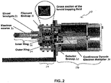
- the miniature toroidal RF mass analyzer 10 consists of three sections: the ionizer assembly 12, the trapping region 14 and the detector assembly 16.
- the ionizer assembly 16 is an ion source for the mass analyzer.
- the ion source includes all means for creating ions externally and generating them within the trapping volume, as understood by those skilled in the art.
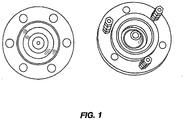
- the trapping region 14 is formed from four separate electrodes (a filament endcap 18, a detector endcap 20 an inner ring electrode 22 and an outer ring electrode 24) as can be seen in the photograph of Figure 1 and in the cross-sectional diagram in Figure 2 .
- the names of the four electrodes 18, 20, 22, 24 arise historically from their 3D trap origin and indicate their location in the assembly (i.e., the filament endcap 18 is the electrode closest to the ionizer; the detector endcap 20 is closest to the detector, etc.). While the 3D ion trap character would still allow the traditional 'axial' and 'radial' dimension terms to be valid if only the cross-sectional trapping geometry is considered, a linear quadrupole model is seemingly more appropriate.
- the x-dimension is defined here as the non-ejection dimension (towards the inner and outer rings 22, 24)
- the y-dimension is defined as the ejection dimension (towards the filament endcap 18 and the detector endcap 20)
- the z-dimension is tangential to the toroidal trapping field.
- the electrodes 18, 20, 22, 24 were precision machined from 316 stainless steel with machine tolerances specified to 0.0005 inch.
- the dimensions of the toroid assembly 10 were scaled to 1/5 of the size of the original (full-size) version and retained the same shaped corrections to the trapping field that were determined for the original version.
- the radius (r 0 ) of the miniature device is 0.2 cm.
- Spacers were machined from alumina or vespelTM and provide slits to allow gas conductance in and out of the trapping region. Entrance and exit slits with dimensions of 0.28 mm were machined into the two endcaps 18, 20 using a plunge electro-discharge machining (EDM) technique to allow the ionization electrons to enter into the trapping region 14 and ejected ions to exit to a detector in the detector assembly 16.
- EDM plunge electro-discharge machining
- the miniature toroidal RF ion trap mass analyzer can be scaled to an even smaller size, perhaps as small as 1/50 the size of a conventional 3D configuration.
- a miniature electron gun 30 was designed to focus source electrons, formed by emission from a heated filament, through a three-element Einzel lens 32 and then through a small section of the annular endcap slit.
- the middle lens (L2) of the electron focusing assembly also acted as a gate to turn the ionization on or off.
- a custom circuit was designed to vary the L2 voltage between -50 V (ionization off) and +125 V (ionization on).
- a current controlled power supply (Lambda, Model LPT-7202-FM) provided both the nominal 20 eV electron energy and the nominal 1.5 A filament current.
- CDEM 34 a conventional, more rugged continuous dynode electron multiplier detector (CDEM) 34 was used in place of a microchannel plate detector previously used in the original version.
- CDEM continuous dynode electron multiplier detector
- a custom CDEM Detector Technologies
- a custom circuit provided a gating voltage on a lens element between the detector endcap and the electron multiplier. This circuit switched between a detector gate closed and a detector gate open configuration.
- a high voltage power supply (Bertan/Spellman, Model 230) provided the detector bias.
- the RF trapping field was established using a custom-built, class C self-resonant tank circuit with a nominal frequency of 1.9 MHz.
- the RF signal was applied to both the inner ring 22 and outer ring 24
- the amplitude of the RF trapping voltage was typically ca. 100-200 V p-p during the ionization and ion cooling portions of the scan.
- the RF amplitude was then scanned over the course of 200 ms to ca. 700-1200 V p-p depending on the mass range desired.
- the RF amplitude was turned off for a short (5 ms) time period to allow all remaining ions to leave the trap prior to the next scan.
- An arbitrary waveform generator (Agilent, Model 33250A) was used to provide the resonant ejection frequency (900 kHz, 8 V p-p ) during the RF scan to produce the spectrum. This signal was applied to both endcaps 18, 20 through a custom Balun amplifier which also contained a DC offset circuit to allow variations in the Mathieu 'a' parameter.
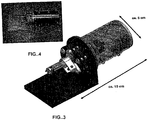
- the entire mass spectrometer analyzer 10 shown in Figure 3 is only 5 cm in diameter and 10 cm long, including the ionizer assembly 12 and the detector assembly 16 which currently comprise the major portions of the length.
- the mass spectrometer was enclosed in a custom vacuum chamber pumped by a 230 L/s turbo pump (BOC Edwards, Model EXT255) backed by a 20 m 3 /h mechanical pump (BOC Edwards, Model E2M18). Pressures were monitored using a full range cold cathode vacuum gauge and controller (Pfeiffer, Model FJKR 251/261). All pressure readings are reported as uncorrected values.
- a simple, four-segment scan function was used to acquire data.
- a period of ionization (10-100 ms) was followed by a period of ion cooling (ca. 10-30 ms).
- the third segment of the scan function ramped the RF to perform the mass analysis, followed by a period of time (ca. 5 ms) during which the RF was turned off and all ions were eliminated from the trapping volume 14 in preparation for the next scan.
- the timing of the scan function segments was controlled by a PIC-16C770 (Microchip Technology) digital microcontroller.
- the PIC was programmable through an I 2 C interface.
- a Windows-based control program, Aardvark I 2 C Control Center (Total Phase) was used to set the timing values in the PIC.
- the digital I/O outputs from the PIC were then used to control the initiation of the signal acquisition integrator, the start of the RF ramp, the control of the arbitrary waveform generator, the gating of the ionizer and detector, and the RF on/off status.
- a multifunction data acquisition (DAO) board (National Instruments Model 6115, Austin, TX) coupled with a multiport connector panel (National Instruments, Model BNC 2110) was used to provide a variable modulation voltage to the RF generator to control the RF ramp.
- Signal from the detector was integrated using a custom preamplifier and sent to either a digital oscilloscope (Agilent, Model 64522A) or to the DAO board where it was digitized by one of the analog-to-digital channels of the multifunction DAO.
- a synchronization pulse started both the signal integrator and the RF ramp simultaneously.
- the signal integrator operated at 30 kHz and provided a digitized signal intensity every 33.3 ⁇ s.
- a typical RF scan would cover approximately 300 daltons in 200 ms, allowing approximately 0.67 ms per dalton. Therefore at 30 kHz, there were approximately 20 samples acquired across each nominal mass.
- the number of signal integrations in the output was linear with time and, therefore, the signal integrator count was used to calibrate the mass scale for the acquired data.
- the toroidal RF ion trap 10 is a two-dimensional trapping device, and if the field corrections employed to compensate for distortions introduced by the analyzer curvature are adequate, the cross-sectional trapping field should look very much like a linear quadrupole.
- q-values (and therefore ⁇ -values) for the x and y dimensions should be the same. This requires, therefore, that the ion's secular frequency in the x and y dimension are similar, if not the same. Because a significant contribution of higher order fields is expected to be present (introduced intentionally or unintentionally), coupling of the ion motion in the x and y dimensions is expected.
- Mass spectral data were obtained for seven different samples (benzene, n-butylbenzene, toluene, chlorobenzene, naphthalene, xenon and toluene) and used to create the mass calibration graph shown in Figure 5 . Since the RF amplitude was scanned linearly and the sample integrator was initiated at the beginning of the RF ramp, there is a direct linear relationship between the sample integrator number and RF amplitude. The calibration table shows the expected linear relationship between mass and RF amplitude.
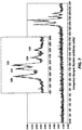
- Figure 7 shows the spectrum obtained for xenon. The expected isotope pattern is observed and each of the isotopes is clearly resolved. Despite the early stage of development, high signal-to-noise spectra were obtained for samples with pressures as low as 2 x 10 6 mbar and ionization times as low as 20 ms. The spectrum for naphthalene under these conditions is shown in Figure 8 . The minor peak in the naphthalene spectrum at m/z 102 is still clearly observable.
- toroidal RF ion trap mass analyzer as described above are for illustration purposes only.
- the present invention should not be considered to be limited by the specific dimensions or other operational parameters given, but should be regarded as one example only. Many dimensions and operational parameters may be modified and the mass analyzer will still operate as desired, in accordance with the understanding of those skilled in the art.
- a means must be provided wherein ions are admitted into and exit from the trapping region 14 as defined by the end caps 18, 20 and the inner ring 22 and the outer ring 24. Ion admission and ejection is accomplished by means of slits and recessed bridges in the filament endcap 18 and the detector endcap 20.
- ion trap mass analyzers As the analyzer dimensions of ion trap mass analyzers become increasingly smaller, machining and other field imperfections can increase in their significance causing deleterious effects on the trapping and mass analysis capabilities of the ion trap. Discontinuities in the trapping field manifest themselves as perturbations to the desired essentially quadrupolar trapping field.
- a homogenous trapping field requires that the electrode surfaces be the same throughout the entire trapping volume.
- slits are cut in the filament endcap 18 and the detector endcap 20. In order to maintain a connection between the inner portion 42 and outer portion 44 of the filament and detector endcaps 18, 20, the slits cannot be cut through the entire cylindrical revolution. A bridge is therefore provided between the inner portion and the outer portion 44.
- Figure 9 is provided as a perspective view of an endcap, wherein the filament endcap 18 and the detector endcap 20 must both allow ions to pass therethrough.
- the endcap shown (either the filament endcap or the detector endcap 20 hereinafter) has three slits 40 that essentially create an inner portion 42 and an outer portion 44.
- the three bridges 46 are not recessed below a surface of the endcap, but are level with the surfaces of the inner portion 42 and the outer portion 44. it is important to understand that the number of slits through the endcap can be modified as needed, and the number of three shown in this embodiment is not a limiting factor of the present embodiment.
- Figure 10 is provided as a cross-sectional view of the endcap shown in Figure 9 .
- the slit 40 completely separates the inner portion 42 and the outer portion 44.
- the bridge 46 is shown as being level with the surface of the inner portion 42 and the outer portion 44. These bridges 46 (when at the surface of the trapping field or endcap electrodes) produce discontinuities in the trapping field and thus it is desirable to minimize their effects.
- Figure 11 is provided as a perspective view of: the endcap still having three slits 40. However, the three bridges 48 are now recessed below a surface of the endcap. The recessed bridges 48 are visible more clearly in the cross-sectional view of the endcap shown in Figure 12 .
- the first embodiment of the present invention thus includes a slit that is a complete 360° circle that only partially penetrates the full thickness of the endcap electrodes. When used, the mechanical bridges 48 are recessed within the slits 40. During ion storage in the trapping region 14, the ions see a uniform slit 40 in the immediate vicinity of the trapping field and in this fashion, the effects of the bridges 48 on the trapping field are minimized.
- Traditional, full-size commercial 3D ion trap mass analyzers have a trapping chamber radius on the order of 1 cm.
- the maximum RF voltage applied to the ring electrode for a maximum mass range of 650 da, and an operating frequency ( ⁇ ) of 1.1 MHz is approximately 15 kV p-p .
- a toroidal ion trap geometry with the same radial dimension and an approximate 3:1 ratio between the radius of the torus (R) to the radius of the cross-sectional trapping field (r 0 ) would have roughly 400 times more ion storage volume than the conventional 3D analyzer.
- the RF voltage (V) required to maintain the same trapping conditions is reduced by the square of the change in r 0 .
- Considerations for the amount of size reduction include 1) ion optic coupling with the entrance cone of the detector and 2) mass range and RF maximum operating voltage.
- the reduction of r 0 leads not only to a smaller mass analyzer, but a lower RF operating voltage also.
- a value of r 0 can be selected such that the approximate ion storage capacity of the reduced toroidal RF ion trap analyzer is similar to that of a conventional, 3D commercial ion trap with a 1 cm radius.
- optimization of the size of the mass analyzer should also be understood as an enhancement of capabilities.
- a smaller mass analyzer will be easier to move ions into a trapping volume, and out to a detector.
- a third embodiment of the present invention it is another aspect of the invention that it is desirable to protect the detector from ions both inside and outside the trapping volume during ionization.
- ions both inside and outside the trapping volume during ionization.
- a large ion current reaches a detector in the detector assembly 16 either indirectly (by scattering), through the ion trap analyzer, or due to the formation of ions whose stability parameters are outside the stability boundary and as such they are immediately ejected from the trap and into the detector.
- This excess, non-mass analyzed current has the deleterious effect of shortening the life of the detector. It is desirable to prevent detector signal during ionization to thereby increase the life of the detector.
- Transmission grids can adequately block the passage of ions to the detector, but they also have the deleterious effect of attenuating the signal during the mass analysis portion of the analytical scan.
- annular detector gate that when biased, prevents a beam of ions from entering the detector assembly 16.
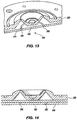
- Figure 13 is provided as a perspective view of the annular detector gate 50.
- Figure 14 is provided as a cross-sectional view.
- Bipolar voltages (+/-) are applied to the inner 52 and outer 54 portion of the gate 50 during ionization to deflect the ejecting ions away from the slit.
- the gate may act as a lens to help focus the beam into the detector.
- the gate may not focus the ions, but just enable their transmission to the detector.
- the detector gate slits 56 are arranged such that there is no line-of-sight from the filament to the detector region as a bridge in the detector gate effectively blocks that path. Since the use of the gate allows the detector voltage to remain on during the entire scan, this 'bridge' alignment also helps reduce the amount of detector signal during ionization.
- the detector gate provides other benefits. For example, using the detector gate allows the detector to remain on. By keeping the detector on, the finite amount of time that would otherwise be required to turn on and turn off the high voltage power supply to the detector is eliminated from the duty cycle of the mass analyzer. An increased duty cycle of the analytical scan is the result.
- detector gate Another benefit of the detector gate is the reduction in latent noise of the system, as understood by those skilled in the art.
Landscapes
- Chemical & Material Sciences (AREA)
- Analytical Chemistry (AREA)
- Other Investigation Or Analysis Of Materials By Electrical Means (AREA)
- Electron Tubes For Measurement (AREA)
Applications Claiming Priority (2)
| Application Number | Priority Date | Filing Date | Title |
|---|---|---|---|
| US75027705P | 2005-12-13 | 2005-12-13 | |
| PCT/US2006/047828 WO2007089339A2 (en) | 2005-12-13 | 2006-12-13 | Miniature toroidal radio frequency ion trap mass analyzer |
Publications (3)
| Publication Number | Publication Date |
|---|---|
| EP1960090A2 EP1960090A2 (en) | 2008-08-27 |
| EP1960090A4 EP1960090A4 (en) | 2011-12-21 |
| EP1960090B1 true EP1960090B1 (en) | 2018-10-10 |
Family
ID=38327834
Family Applications (1)
| Application Number | Title | Priority Date | Filing Date |
|---|---|---|---|
| EP06849962.3A Active EP1960090B1 (en) | 2005-12-13 | 2006-12-13 | Miniature toroidal radio frequency ion trap mass analyzer |
Country Status (6)
| Country | Link |
|---|---|
| US (1) | US9053919B2 (ja) |
| EP (1) | EP1960090B1 (ja) |
| JP (2) | JP5491734B2 (ja) |
| CN (1) | CN101330965B (ja) |
| CA (1) | CA2632578A1 (ja) |
| WO (1) | WO2007089339A2 (ja) |
Families Citing this family (11)
| Publication number | Priority date | Publication date | Assignee | Title |
|---|---|---|---|---|
| GB201103361D0 (en) * | 2011-02-28 | 2011-04-13 | Shimadzu Corp | Mass analyser and method of mass analysis |
| WO2013039772A1 (en) | 2011-09-16 | 2013-03-21 | Waters Technologies Corporation | Techniques for automated performance maintenance testing and reporting for analytical instruments |
| WO2014149846A2 (en) | 2013-03-15 | 2014-09-25 | 1St Detect Corporation | A mass spectrometer system having an external detector |
| US8878127B2 (en) * | 2013-03-15 | 2014-11-04 | The University Of North Carolina Of Chapel Hill | Miniature charged particle trap with elongated trapping region for mass spectrometry |
| CN103928288B (zh) * | 2014-04-17 | 2017-01-04 | 复旦大学 | 一种用于离子储存与质量分析的三角形圆环离子阱 |
| US9711341B2 (en) * | 2014-06-10 | 2017-07-18 | The University Of North Carolina At Chapel Hill | Mass spectrometry systems with convective flow of buffer gas for enhanced signals and related methods |
| CN104900474B (zh) * | 2015-05-26 | 2017-02-01 | 清华大学深圳研究生院 | 一种串联离子阱 |
| CN105632864B (zh) * | 2016-01-07 | 2017-11-17 | 中国计量科学研究院 | 一种复合检测器及具有该检测器的四极质谱仪 |
| CA3039916A1 (en) | 2016-10-10 | 2018-04-19 | Perkinelmer Health Sciences, Inc. | Sampling pumps and closed loop control of sampling pumps to load traps |
| US10242857B2 (en) | 2017-08-31 | 2019-03-26 | The University Of North Carolina At Chapel Hill | Ion traps with Y-directional ion manipulation for mass spectrometry and related mass spectrometry systems and methods |
| WO2023150680A1 (en) * | 2022-02-04 | 2023-08-10 | Perkinelmer Health Sciences, Inc. | Toroidal ion trap |
Citations (1)
| Publication number | Priority date | Publication date | Assignee | Title |
|---|---|---|---|---|
| US5420425A (en) * | 1994-05-27 | 1995-05-30 | Finnigan Corporation | Ion trap mass spectrometer system and method |
Family Cites Families (12)
| Publication number | Priority date | Publication date | Assignee | Title |
|---|---|---|---|---|
| DE4324224C1 (de) * | 1993-07-20 | 1994-10-06 | Bruker Franzen Analytik Gmbh | Quadrupol-Ionenfallen mit schaltbaren Multipol-Anteilen |
| US5650617A (en) * | 1996-07-30 | 1997-07-22 | Varian Associates, Inc. | Method for trapping ions into ion traps and ion trap mass spectrometer system thereof |
| JP3656239B2 (ja) * | 1997-01-28 | 2005-06-08 | 株式会社島津製作所 | イオントラップ質量分析装置 |
| JP3617662B2 (ja) * | 1997-02-28 | 2005-02-09 | 株式会社島津製作所 | 質量分析装置 |
| JP3650551B2 (ja) | 1999-09-14 | 2005-05-18 | 株式会社日立製作所 | 質量分析計 |
| US6762406B2 (en) * | 2000-05-25 | 2004-07-13 | Purdue Research Foundation | Ion trap array mass spectrometer |
| CA2446964C (en) * | 2001-05-08 | 2010-07-20 | Thermo Finnigan Llc | Ion trap |
| US6770871B1 (en) * | 2002-05-31 | 2004-08-03 | Michrom Bioresources, Inc. | Two-dimensional tandem mass spectrometry |
| CA2529597A1 (en) | 2003-06-20 | 2004-12-29 | Brigham Young University | Single device for ion mobility and ion trap mass spectrometry |
| US7217922B2 (en) * | 2005-03-14 | 2007-05-15 | Lucent Technologies Inc. | Planar micro-miniature ion trap devices |
| US7180057B1 (en) * | 2005-08-04 | 2007-02-20 | Thermo Finnigan Llc | Two-dimensional quadrupole ion trap |
| US20100163724A1 (en) * | 2008-12-30 | 2010-07-01 | University Of North Texas | Applications of hydrogen gas getters in mass spectrometry |
-
2006
- 2006-12-13 EP EP06849962.3A patent/EP1960090B1/en active Active
- 2006-12-13 JP JP2008545830A patent/JP5491734B2/ja active Active
- 2006-12-13 WO PCT/US2006/047828 patent/WO2007089339A2/en active Application Filing
- 2006-12-13 CA CA002632578A patent/CA2632578A1/en not_active Abandoned
- 2006-12-13 US US11/639,373 patent/US9053919B2/en active Active
- 2006-12-13 CN CN2006800470443A patent/CN101330965B/zh active Active
-
2013
- 2013-12-27 JP JP2013271795A patent/JP5805746B2/ja active Active
Patent Citations (1)
| Publication number | Priority date | Publication date | Assignee | Title |
|---|---|---|---|---|
| US5420425A (en) * | 1994-05-27 | 1995-05-30 | Finnigan Corporation | Ion trap mass spectrometer system and method |
Non-Patent Citations (1)
| Title |
|---|
| LAMMERT S A ET AL: "Design, optimization and initial performance of a toroidal rf ion trap mass spectrometer", INTERNATIONAL JOURNAL OF MASS SPECTROMETRY, ELSEVIER SCIENCE PUBLISHERS, AMSTERDAM, NL, vol. 212, no. 1-3, 15 November 2001 (2001-11-15), pages 25 - 40, XP004339989, ISSN: 1387-3806, DOI: 10.1016/S1387-3806(01)00507-3 * |
Also Published As
| Publication number | Publication date |
|---|---|
| EP1960090A4 (en) | 2011-12-21 |
| JP2009519584A (ja) | 2009-05-14 |
| US20120267523A1 (en) | 2012-10-25 |
| US9053919B2 (en) | 2015-06-09 |
| EP1960090A2 (en) | 2008-08-27 |
| WO2007089339A2 (en) | 2007-08-09 |
| JP5805746B2 (ja) | 2015-11-04 |
| JP5491734B2 (ja) | 2014-05-14 |
| WO2007089339A3 (en) | 2008-04-03 |
| JP2014078532A (ja) | 2014-05-01 |
| CA2632578A1 (en) | 2007-08-09 |
| CN101330965B (zh) | 2012-05-30 |
| CN101330965A (zh) | 2008-12-24 |
Similar Documents
| Publication | Publication Date | Title |
|---|---|---|
| EP1960090B1 (en) | Miniature toroidal radio frequency ion trap mass analyzer | |
| AU2003297655B2 (en) | Processes for designing mass separators and ion traps, methods for producing mass separators and ion traps. mass spectrometers, ion traps, and methods for analysing samples | |
| Lammert et al. | Miniature toroidal radio frequency ion trap mass analyzer | |
| US7075070B2 (en) | Single device for ion mobility and ion trap mass spectrometry | |
| EP2786399B1 (en) | Method for automated checking and adjustment of mass spectrometer calibration | |
| US7456389B2 (en) | High throughput quadrupolar ion trap | |
| US7446310B2 (en) | High throughput quadrupolar ion trap | |
| EP2858091A1 (en) | Method and apparatus for a combined linear ion trap and quadrupole mass filter | |
| Wang et al. | Performance and geometry optimization of the ceramic‐based rectilinear ion traps | |
| US20160071709A1 (en) | Apparatus and Methods for Controlling Miniaturized Arrays of Ion Traps | |
| US6182831B1 (en) | Magnetic separator for linear dispersion and method for producing the same | |
| CN111029242A (zh) | 一种用于四极杆质量分析器的离子信号检测装置和方法 | |
| Brkić et al. | An optimised quadrupole mass spectrometer with a dual filter analyser for in-field chemical sniffing of volatile organic compounds | |
| CN112689885A (zh) | 用于减少高丰度离子的动态离子过滤器 | |
| Snyder et al. | Unique capabilities of AC frequency scanning and its implementation on a Mars Organic Molecule Analyzer linear ion trap | |
| Dziekonski et al. | Voltage-induced frequency drift correction in fourier transform electrostatic linear ion trap mass spectrometry using mirror-switching | |
| US7576324B2 (en) | Ion detection methods, mass spectrometry analysis methods, and mass spectrometry instrument circuitry | |
| Schultze | Advanced System Components for the Development of a Handheld Ion Trap Mass Spectrometer | |
| Agarwal et al. | A review on analyzers for mass spectrometry | |
| EP4235746A1 (en) | Method and apparatus of mass analysing positively charged ions and negatively charged ions | |
| Chernookiy | Optimization of the cylindrical ion trap geometry for mass analysis at high pressure | |
| CN112992649A (zh) | 一种标准四极场线形离子阱质量分析器 | |
| Wang | Halo ion trap mass spectrometry: Design, instrumentation, and performance | |
| GB2474152A (en) | Multi-electrode ion trap | |
| Schwieters et al. | A new thermal ionization mass spectrometer (TIMS) |
Legal Events
| Date | Code | Title | Description |
|---|---|---|---|
| PUAI | Public reference made under article 153(3) epc to a published international application that has entered the european phase |
Free format text: ORIGINAL CODE: 0009012 |
|
| 17P | Request for examination filed |
Effective date: 20080616 |
|
| AK | Designated contracting states |
Kind code of ref document: A2 Designated state(s): AT BE BG CH CY CZ DE DK EE ES FI FR GB GR HU IE IS IT LI LT LU LV MC NL PL PT RO SE SI SK TR |
|
| AX | Request for extension of the european patent |
Extension state: AL BA HR MK RS |
|
| A4 | Supplementary search report drawn up and despatched |
Effective date: 20111118 |
|
| RIC1 | Information provided on ipc code assigned before grant |
Ipc: H01J 49/42 20060101ALI20111114BHEP Ipc: B01D 59/44 20060101AFI20111114BHEP Ipc: H01J 49/00 20060101ALI20111114BHEP Ipc: H01J 49/04 20060101ALI20111114BHEP |
|
| DAX | Request for extension of the european patent (deleted) | ||
| 17Q | First examination report despatched |
Effective date: 20140206 |
|
| GRAP | Despatch of communication of intention to grant a patent |
Free format text: ORIGINAL CODE: EPIDOSNIGR1 |
|
| INTG | Intention to grant announced |
Effective date: 20180405 |
|
| GRAS | Grant fee paid |
Free format text: ORIGINAL CODE: EPIDOSNIGR3 |
|
| GRAJ | Information related to disapproval of communication of intention to grant by the applicant or resumption of examination proceedings by the epo deleted |
Free format text: ORIGINAL CODE: EPIDOSDIGR1 |
|
| GRAL | Information related to payment of fee for publishing/printing deleted |
Free format text: ORIGINAL CODE: EPIDOSDIGR3 |
|
| GRAR | Information related to intention to grant a patent recorded |
Free format text: ORIGINAL CODE: EPIDOSNIGR71 |
|
| INTC | Intention to grant announced (deleted) | ||
| GRAA | (expected) grant |
Free format text: ORIGINAL CODE: 0009210 |
|
| AK | Designated contracting states |
Kind code of ref document: B1 Designated state(s): AT BE BG CH CY CZ DE DK EE ES FI FR GB GR HU IE IS IT LI LT LU LV MC NL PL PT RO SE SI SK TR |
|
| INTG | Intention to grant announced |
Effective date: 20180903 |
|
| REG | Reference to a national code |
Ref country code: GB Ref legal event code: FG4D |
|
| REG | Reference to a national code |
Ref country code: CH Ref legal event code: EP Ref country code: AT Ref legal event code: REF Ref document number: 1050584 Country of ref document: AT Kind code of ref document: T Effective date: 20181015 |
|
| REG | Reference to a national code |
Ref country code: IE Ref legal event code: FG4D |
|
| REG | Reference to a national code |
Ref country code: DE Ref legal event code: R096 Ref document number: 602006056577 Country of ref document: DE |
|
| REG | Reference to a national code |
Ref country code: NL Ref legal event code: MP Effective date: 20181010 |
|
| REG | Reference to a national code |
Ref country code: LT Ref legal event code: MG4D |
|
| REG | Reference to a national code |
Ref country code: AT Ref legal event code: MK05 Ref document number: 1050584 Country of ref document: AT Kind code of ref document: T Effective date: 20181010 |
|
| PG25 | Lapsed in a contracting state [announced via postgrant information from national office to epo] |
Ref country code: NL Free format text: LAPSE BECAUSE OF FAILURE TO SUBMIT A TRANSLATION OF THE DESCRIPTION OR TO PAY THE FEE WITHIN THE PRESCRIBED TIME-LIMIT Effective date: 20181010 |
|
| PG25 | Lapsed in a contracting state [announced via postgrant information from national office to epo] |
Ref country code: BG Free format text: LAPSE BECAUSE OF FAILURE TO SUBMIT A TRANSLATION OF THE DESCRIPTION OR TO PAY THE FEE WITHIN THE PRESCRIBED TIME-LIMIT Effective date: 20190110 Ref country code: IS Free format text: LAPSE BECAUSE OF FAILURE TO SUBMIT A TRANSLATION OF THE DESCRIPTION OR TO PAY THE FEE WITHIN THE PRESCRIBED TIME-LIMIT Effective date: 20190210 Ref country code: ES Free format text: LAPSE BECAUSE OF FAILURE TO SUBMIT A TRANSLATION OF THE DESCRIPTION OR TO PAY THE FEE WITHIN THE PRESCRIBED TIME-LIMIT Effective date: 20181010 Ref country code: LT Free format text: LAPSE BECAUSE OF FAILURE TO SUBMIT A TRANSLATION OF THE DESCRIPTION OR TO PAY THE FEE WITHIN THE PRESCRIBED TIME-LIMIT Effective date: 20181010 Ref country code: LV Free format text: LAPSE BECAUSE OF FAILURE TO SUBMIT A TRANSLATION OF THE DESCRIPTION OR TO PAY THE FEE WITHIN THE PRESCRIBED TIME-LIMIT Effective date: 20181010 Ref country code: AT Free format text: LAPSE BECAUSE OF FAILURE TO SUBMIT A TRANSLATION OF THE DESCRIPTION OR TO PAY THE FEE WITHIN THE PRESCRIBED TIME-LIMIT Effective date: 20181010 Ref country code: PL Free format text: LAPSE BECAUSE OF FAILURE TO SUBMIT A TRANSLATION OF THE DESCRIPTION OR TO PAY THE FEE WITHIN THE PRESCRIBED TIME-LIMIT Effective date: 20181010 Ref country code: FI Free format text: LAPSE BECAUSE OF FAILURE TO SUBMIT A TRANSLATION OF THE DESCRIPTION OR TO PAY THE FEE WITHIN THE PRESCRIBED TIME-LIMIT Effective date: 20181010 |
|
| PG25 | Lapsed in a contracting state [announced via postgrant information from national office to epo] |
Ref country code: PT Free format text: LAPSE BECAUSE OF FAILURE TO SUBMIT A TRANSLATION OF THE DESCRIPTION OR TO PAY THE FEE WITHIN THE PRESCRIBED TIME-LIMIT Effective date: 20190210 Ref country code: SE Free format text: LAPSE BECAUSE OF FAILURE TO SUBMIT A TRANSLATION OF THE DESCRIPTION OR TO PAY THE FEE WITHIN THE PRESCRIBED TIME-LIMIT Effective date: 20181010 Ref country code: GR Free format text: LAPSE BECAUSE OF FAILURE TO SUBMIT A TRANSLATION OF THE DESCRIPTION OR TO PAY THE FEE WITHIN THE PRESCRIBED TIME-LIMIT Effective date: 20190111 |
|
| REG | Reference to a national code |
Ref country code: DE Ref legal event code: R097 Ref document number: 602006056577 Country of ref document: DE |
|
| PG25 | Lapsed in a contracting state [announced via postgrant information from national office to epo] |
Ref country code: IT Free format text: LAPSE BECAUSE OF FAILURE TO SUBMIT A TRANSLATION OF THE DESCRIPTION OR TO PAY THE FEE WITHIN THE PRESCRIBED TIME-LIMIT Effective date: 20181010 Ref country code: DK Free format text: LAPSE BECAUSE OF FAILURE TO SUBMIT A TRANSLATION OF THE DESCRIPTION OR TO PAY THE FEE WITHIN THE PRESCRIBED TIME-LIMIT Effective date: 20181010 Ref country code: CZ Free format text: LAPSE BECAUSE OF FAILURE TO SUBMIT A TRANSLATION OF THE DESCRIPTION OR TO PAY THE FEE WITHIN THE PRESCRIBED TIME-LIMIT Effective date: 20181010 |
|
| REG | Reference to a national code |
Ref country code: CH Ref legal event code: PL |
|
| PLBE | No opposition filed within time limit |
Free format text: ORIGINAL CODE: 0009261 |
|
| STAA | Information on the status of an ep patent application or granted ep patent |
Free format text: STATUS: NO OPPOSITION FILED WITHIN TIME LIMIT |
|
| PG25 | Lapsed in a contracting state [announced via postgrant information from national office to epo] |
Ref country code: EE Free format text: LAPSE BECAUSE OF FAILURE TO SUBMIT A TRANSLATION OF THE DESCRIPTION OR TO PAY THE FEE WITHIN THE PRESCRIBED TIME-LIMIT Effective date: 20181010 Ref country code: LU Free format text: LAPSE BECAUSE OF NON-PAYMENT OF DUE FEES Effective date: 20181213 Ref country code: RO Free format text: LAPSE BECAUSE OF FAILURE TO SUBMIT A TRANSLATION OF THE DESCRIPTION OR TO PAY THE FEE WITHIN THE PRESCRIBED TIME-LIMIT Effective date: 20181010 Ref country code: SK Free format text: LAPSE BECAUSE OF FAILURE TO SUBMIT A TRANSLATION OF THE DESCRIPTION OR TO PAY THE FEE WITHIN THE PRESCRIBED TIME-LIMIT Effective date: 20181010 Ref country code: MC Free format text: LAPSE BECAUSE OF FAILURE TO SUBMIT A TRANSLATION OF THE DESCRIPTION OR TO PAY THE FEE WITHIN THE PRESCRIBED TIME-LIMIT Effective date: 20181010 |
|
| 26N | No opposition filed |
Effective date: 20190711 |
|
| REG | Reference to a national code |
Ref country code: IE Ref legal event code: MM4A |
|
| REG | Reference to a national code |
Ref country code: BE Ref legal event code: MM Effective date: 20181231 |
|
| PG25 | Lapsed in a contracting state [announced via postgrant information from national office to epo] |
Ref country code: SI Free format text: LAPSE BECAUSE OF FAILURE TO SUBMIT A TRANSLATION OF THE DESCRIPTION OR TO PAY THE FEE WITHIN THE PRESCRIBED TIME-LIMIT Effective date: 20181010 Ref country code: IE Free format text: LAPSE BECAUSE OF NON-PAYMENT OF DUE FEES Effective date: 20181213 |
|
| PG25 | Lapsed in a contracting state [announced via postgrant information from national office to epo] |
Ref country code: BE Free format text: LAPSE BECAUSE OF NON-PAYMENT OF DUE FEES Effective date: 20181231 |
|
| PG25 | Lapsed in a contracting state [announced via postgrant information from national office to epo] |
Ref country code: LI Free format text: LAPSE BECAUSE OF NON-PAYMENT OF DUE FEES Effective date: 20181231 Ref country code: CH Free format text: LAPSE BECAUSE OF NON-PAYMENT OF DUE FEES Effective date: 20181231 |
|
| PG25 | Lapsed in a contracting state [announced via postgrant information from national office to epo] |
Ref country code: TR Free format text: LAPSE BECAUSE OF FAILURE TO SUBMIT A TRANSLATION OF THE DESCRIPTION OR TO PAY THE FEE WITHIN THE PRESCRIBED TIME-LIMIT Effective date: 20181010 |
|
| PG25 | Lapsed in a contracting state [announced via postgrant information from national office to epo] |
Ref country code: CY Free format text: LAPSE BECAUSE OF FAILURE TO SUBMIT A TRANSLATION OF THE DESCRIPTION OR TO PAY THE FEE WITHIN THE PRESCRIBED TIME-LIMIT Effective date: 20181010 Ref country code: HU Free format text: LAPSE BECAUSE OF FAILURE TO SUBMIT A TRANSLATION OF THE DESCRIPTION OR TO PAY THE FEE WITHIN THE PRESCRIBED TIME-LIMIT; INVALID AB INITIO Effective date: 20061213 |
|
| PGFP | Annual fee paid to national office [announced via postgrant information from national office to epo] |
Ref country code: GB Payment date: 20231220 Year of fee payment: 18 |
|
| PGFP | Annual fee paid to national office [announced via postgrant information from national office to epo] |
Ref country code: FR Payment date: 20231221 Year of fee payment: 18 Ref country code: DE Payment date: 20231214 Year of fee payment: 18 |