EP1959240B1 - Encodeur et son procédé de fonctionnement - Google Patents
Encodeur et son procédé de fonctionnement Download PDFInfo
- Publication number
- EP1959240B1 EP1959240B1 EP07024089.0A EP07024089A EP1959240B1 EP 1959240 B1 EP1959240 B1 EP 1959240B1 EP 07024089 A EP07024089 A EP 07024089A EP 1959240 B1 EP1959240 B1 EP 1959240B1
- Authority
- EP
- European Patent Office
- Prior art keywords
- voltage
- detector
- pulse
- component group
- voltage source
- Prior art date
- Legal status (The legal status is an assumption and is not a legal conclusion. Google has not performed a legal analysis and makes no representation as to the accuracy of the status listed.)
- Active
Links
- 238000000034 method Methods 0.000 title claims description 12
- 230000015654 memory Effects 0.000 claims description 28
- 238000004804 winding Methods 0.000 claims description 14
- 230000001960 triggered effect Effects 0.000 claims description 10
- 230000005672 electromagnetic field Effects 0.000 claims description 9
- 238000013459 approach Methods 0.000 claims description 5
- 230000006870 function Effects 0.000 claims description 5
- 239000004020 conductor Substances 0.000 description 16
- 230000005284 excitation Effects 0.000 description 13
- 230000003287 optical effect Effects 0.000 description 6
- 230000001939 inductive effect Effects 0.000 description 5
- 239000000758 substrate Substances 0.000 description 5
- 239000003990 capacitor Substances 0.000 description 4
- 238000001514 detection method Methods 0.000 description 4
- 230000004048 modification Effects 0.000 description 4
- 238000012986 modification Methods 0.000 description 4
- 230000001419 dependent effect Effects 0.000 description 3
- RYGMFSIKBFXOCR-UHFFFAOYSA-N Copper Chemical compound [Cu] RYGMFSIKBFXOCR-UHFFFAOYSA-N 0.000 description 2
- 229910052802 copper Inorganic materials 0.000 description 2
- 239000010949 copper Substances 0.000 description 2
- 230000005291 magnetic effect Effects 0.000 description 2
- 239000000463 material Substances 0.000 description 2
- 230000000717 retained effect Effects 0.000 description 2
- 230000004913 activation Effects 0.000 description 1
- 230000015572 biosynthetic process Effects 0.000 description 1
- 230000000694 effects Effects 0.000 description 1
- 238000005265 energy consumption Methods 0.000 description 1
- 239000003822 epoxy resin Substances 0.000 description 1
- 238000011156 evaluation Methods 0.000 description 1
- 230000005415 magnetization Effects 0.000 description 1
- 238000004519 manufacturing process Methods 0.000 description 1
- 230000000737 periodic effect Effects 0.000 description 1
- 229920000647 polyepoxide Polymers 0.000 description 1
- 230000003319 supportive effect Effects 0.000 description 1
Images


Classifications
-
- G—PHYSICS
- G01—MEASURING; TESTING
- G01D—MEASURING NOT SPECIALLY ADAPTED FOR A SPECIFIC VARIABLE; ARRANGEMENTS FOR MEASURING TWO OR MORE VARIABLES NOT COVERED IN A SINGLE OTHER SUBCLASS; TARIFF METERING APPARATUS; MEASURING OR TESTING NOT OTHERWISE PROVIDED FOR
- G01D5/00—Mechanical means for transferring the output of a sensing member; Means for converting the output of a sensing member to another variable where the form or nature of the sensing member does not constrain the means for converting; Transducers not specially adapted for a specific variable
- G01D5/12—Mechanical means for transferring the output of a sensing member; Means for converting the output of a sensing member to another variable where the form or nature of the sensing member does not constrain the means for converting; Transducers not specially adapted for a specific variable using electric or magnetic means
- G01D5/244—Mechanical means for transferring the output of a sensing member; Means for converting the output of a sensing member to another variable where the form or nature of the sensing member does not constrain the means for converting; Transducers not specially adapted for a specific variable using electric or magnetic means influencing characteristics of pulses or pulse trains; generating pulses or pulse trains
- G01D5/245—Mechanical means for transferring the output of a sensing member; Means for converting the output of a sensing member to another variable where the form or nature of the sensing member does not constrain the means for converting; Transducers not specially adapted for a specific variable using electric or magnetic means influencing characteristics of pulses or pulse trains; generating pulses or pulse trains using a variable number of pulses in a train
- G01D5/2451—Incremental encoders
-
- G—PHYSICS
- G01—MEASURING; TESTING
- G01D—MEASURING NOT SPECIALLY ADAPTED FOR A SPECIFIC VARIABLE; ARRANGEMENTS FOR MEASURING TWO OR MORE VARIABLES NOT COVERED IN A SINGLE OTHER SUBCLASS; TARIFF METERING APPARATUS; MEASURING OR TESTING NOT OTHERWISE PROVIDED FOR
- G01D5/00—Mechanical means for transferring the output of a sensing member; Means for converting the output of a sensing member to another variable where the form or nature of the sensing member does not constrain the means for converting; Transducers not specially adapted for a specific variable
- G01D5/26—Mechanical means for transferring the output of a sensing member; Means for converting the output of a sensing member to another variable where the form or nature of the sensing member does not constrain the means for converting; Transducers not specially adapted for a specific variable characterised by optical transfer means, i.e. using infrared, visible, or ultraviolet light
- G01D5/32—Mechanical means for transferring the output of a sensing member; Means for converting the output of a sensing member to another variable where the form or nature of the sensing member does not constrain the means for converting; Transducers not specially adapted for a specific variable characterised by optical transfer means, i.e. using infrared, visible, or ultraviolet light with attenuation or whole or partial obturation of beams of light
- G01D5/34—Mechanical means for transferring the output of a sensing member; Means for converting the output of a sensing member to another variable where the form or nature of the sensing member does not constrain the means for converting; Transducers not specially adapted for a specific variable characterised by optical transfer means, i.e. using infrared, visible, or ultraviolet light with attenuation or whole or partial obturation of beams of light the beams of light being detected by photocells
- G01D5/347—Mechanical means for transferring the output of a sensing member; Means for converting the output of a sensing member to another variable where the form or nature of the sensing member does not constrain the means for converting; Transducers not specially adapted for a specific variable characterised by optical transfer means, i.e. using infrared, visible, or ultraviolet light with attenuation or whole or partial obturation of beams of light the beams of light being detected by photocells using displacement encoding scales
- G01D5/3473—Circular or rotary encoders
Definitions
- the invention relates to a rotary encoder for determining relative angular positions according to claim 1, and to a method for its operation according to claim 7.
- Such encoders are often used to determine the angular position of two relatively rotatable machine parts and work, for example, an inductive measuring principle.
- excitation windings and receiver windings are applied approximately in the form of printed conductors on a common printed circuit board, which is firmly connected, for example, with a stator of the rotary encoder.
- This printed circuit board opposite is located at a defined axial distance and centered on another board, which is formed as a code element or preferably annular code disc on the periodically spaced electrically conductive and non-conductive surfaces are applied as a division or division structure, and which with the Rotor of the encoder is rotatably connected.
- such encoders are used as measuring devices for electric drives, for determining the absolute angular position of corresponding drive shafts.
- a steering angle sensor which has a pulse wire which provides sufficient electrical energy for autonomous activation of a count memory.
- the present invention is based on the object to provide a rotary encoder, in particular an inductive rotary encoder, whose power consumption is minimized in a predetermined operating mode.
- the rotary encoder comprises a first component group and a second component group, wherein the two component groups are arranged rotatable relative to each other about an axis.
- the first group of components comprises a pulse wire, at least one detector and an electronic circuit with a logic circuit and a non-volatile memory.
- the second component group in turn has a magnet and at least one code element.
- a voltage pulse can be generated, Furthermore, depending on the relative position of the code element to the at least one detector of this a signal generated, which can be determined by the logic circuit, based on the signal position information which is storable in the non-volatile memory.
- the first part group is configured so that the circuit, triggered by the occurrence of the voltage pulse with a voltage of a voltage source can be acted upon, wherein the pulse wire to the voltage source is connected in parallel, so that the voltage pulse of the pulse wire contributes to the power supply of the circuit, and the circuit at the latest after storing the position information in the non-volatile memory of this Voltage source is separable again.
- Such an arrangement has the particular advantage that the rotary encoder consumes only energy from the voltage source for determining and storing the position information when a rotational movement actually takes place.
- the voltage source can advantageously be accommodated directly in the rotary encoder, in particular in the first component group, or externally, so that the electrical energy supplied by the voltage source can reach the rotary encoder via a cable.
- rotary encoders are supplied with electrical energy via the mains supply in a "normal" operating mode. In the event that this supply is interrupted, the rotary encoder can go into a second operating mode, in which they are powered by another, redundant power source, such as a battery.
- the present invention is particularly suitable for rotary encoders in which a switchover from a first operating mode to a second operating mode is possible, wherein the electrical power consumption of the rotary encoder in the second operating mode is smaller than in the first operating mode.
- the rotary encoder is configured according to the features of the invention, in particular the first component group is configured so that in the second operating mode, the circuit triggered by the occurrence of the voltage pulse with a voltage of a voltage source can be acted upon and the circuit at the latest after storing the position information in the non-volatile memory of this voltage source is separable again.
- the position information represents the information about the relative position, ie about angular position, of the first component group relative to the second component group and can be specified, for example, in degrees.
- the first component group is designed as a stator and the second component group as a rotor.
- the first component group may comprise an emitter, by which an electromagnetic field can be generated, which is modulated by the at least one code element, so that depending on the relative position of the code element to the at least one detector, a signal can be generated.
- the first component group is configured such that the emitter, triggered by the occurrence of the voltage pulse, can be acted upon by a voltage of a voltage source and the emitter can be disconnected from the voltage source again at the latest after the position information has been stored in the non-volatile memory.
- the emitter comprises an excitation winding through which an electromagnetic field can be generated, in which case the at least one detector is designed as a receiver winding.
- the rotary encoder works according to an inductive measuring principle.
- the invention can also be applied to a capacitive or optical rotary encoder.
- the emitter can then comprise a light source and the at least one detector can be designed as a photoelement.
- the first component group is configured such that the at least one detector, triggered by the occurrence of the voltage pulse, can be acted upon by a voltage of a voltage source and can be separated again from the voltage source. In this way, not only the operating time of the circuit with the logic circuit and the non-volatile memory is minimized, but also the turn-on time of the at least one detector is reduced to a minimum.
- the at least one code element is designed as a magnet and the at least one detector is an MR or Hall element.
- the invention relates to rotary encoders which are configured in such a way that the voltage pulse of the pulse wire does not contribute to the actual determination of the position information in the narrower sense, but only relevant with regard to the connection of the voltage source to the power supply is.
- the rotary encoder can also be configured so that the occurrence of the voltage pulse is also used for determining the position information, in particular for direction detection, together with the signal of a detector.
- the invention comprises a method for operating a rotary encoder, in which the rotary encoder comprises a first component group and a second component group and the component groups are arranged rotatably relative to an axis.
- the first group of components comprises a pulse wire, at least one detector and an electronic circuit with a logic circuit and a non-volatile memory.
- the second component group in turn has a magnet and at least one code element. When the magnet approaches the pulse wire, a voltage pulse is generated by the pulse wire. Thereafter, depending on the relative position of the code element to the at least one detector, a signal is generated therefrom. Based on the signal of the detector, a position information is then determined by the logic circuit, which is stored in the next step in the non-volatile memory.
- the occurrence of the voltage pulse triggers that the circuit is supplied with a voltage of a voltage source, and the pulse wire to the voltage source is connected in parallel, so that the voltage pulse of the pulse wire contributes to the power supply of the circuit, at the latest after storing the position information in the non-volatile Memory the circuit is disconnected from the power source again.
- the rotary encoder automatically switches over from the first operating mode to the second, the method according to the invention being used in the second operating mode.
- a second group of components may comprise code elements in a plurality of pitch tracks which are of different fineness and therefore provide different numbers of signal periods per one relative rotation as they are scanned by the detectors.
- the rotary encoder is configured so that in the operating mode in which the circuit can be acted upon by a voltage of the voltage source only that pitch track is scanned, which provides the least number of signal periods per one relative rotation. According to a modification can also be scanned in the said state to increase the accuracy of several graduation tracks:
- FIG. 1 is a sectional view through a rotary encoder according to an embodiment shown.
- the rotary encoder therefore comprises a first component group, here in the function of a stator 1 and a second component group, acting here as a rotor 2.
- Rotor 2 and stator 1 are arranged rotatable about an axis A relative to each other.
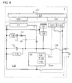
- the stator 1 comprises a housing 1.14, to which an annular Abtastleiterplatte 1.12 is attached. Among other things, a connector 1.13 is mounted on the Abtastleiterplatte 1.12, through which signals and electrical power between the encoder and a subsequent electronics can be transmitted. Further, on the Abtastleiterplatte 1.12, according to the FIG. 4 , a pulse wire 1.1 and components of an electronic circuit 1.5, and an excitation circuit 1.10 arranged. On the scanning circuit board 1.12 is also a voltage source in the form of a battery 1.7.
- the Abtastleiterplatte 1.12 itself has a central bore and is designed in several layers.
- the scanning circuit board 1.12 serves as a carrier body for detectors, which here consist of different receiver windings 1.21, 1.22.
- the inner receiver windings 1.21 include a first receiver trace 1.211 and a second receiver trace 1.212. Within one revolution, both the first receiver track 1.211 and the second receiver track 1.212 each provide a signal period, wherein the signal of the first receiver track 1.211 is shifted by 90 ° with respect to that of the second receiver track 1.212.
- the outer receiver windings 1.22 also consist of two receiver tracks and are designed to provide two signals offset by 90 °, comprising sixteen signal periods per revolution.
- the rotor 2 comprises a shaft 2.1, which can be rotatably mounted, for example, on a motor shaft to be measured.
- a code element designed here as a code disc 2.2, with graduation tracks 2.21, 2.22 fixed against rotation.
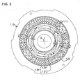
- the code disc 2.2 is shown in a plan view.
- the code disc 2.2. consists of a substrate, which is made in the illustrated embodiment of epoxy resin and on the two graduation tracks 2.21, 2.22 are arranged.
- the graduation tracks 2.21, 2.22 are ring-shaped and arranged with respect to the axis of rotation A concentric with different diameters on the substrate.
- the two graduation tracks 2.21, 2.22 each consist of a periodic sequence of alternately arranged electrically conductive graduation regions 2.211, 2.221 and nonconductive graduation regions 2.212, 2.222.
- the substrate was not coated.
- the inner graduation track 2.21 consists in the illustrated embodiment of a first semi-annular dividing area 2.211 with electrically conductive material, here copper, and a second semi-annular dividing area 2.212, in which no conductive material is arranged.
- the second graduation track 2.22 lies on the substrate, the graduation track 2.22 also consisting of a multiplicity of electrically conductive graduation areas 2.221 and non-conductive graduation areas 2.222 arranged therebetween.
- the different division regions 2.221, 2.222 are material-wise formed in the same way as the division regions 2.211, 2.212 of the first division track 2.21.
- the second graduation track 2.22 in the illustrated embodiment comprises sixteen periodically arranged, electrically conductive graduation regions 2.221 and correspondingly sixteen non-conductive graduation regions 2.222 arranged therebetween.
- the code disk 2.2 has a magnet 2.23, which is arranged on the edge of the code disk 2.2 and is magnetized in a direction parallel to the axis A.
- the code disk 2.2 and the scanning printed circuit board 1.12 face each other at an axial distance, so that the axis A passes through the centers of both elements and in a relative rotation between code disc 2.2 and scanning board 1.12 of the respective angular position dependent signals ⁇ 1.211 , ⁇ 1.212 are generated by In-production effects.
- the pulse wire 1.1 and the magnet 2.23 are arranged to each other so that when approaching the magnet 2.23 to the pulse wire 1: 1 of the pulse wire 1.1, a voltage pulse ⁇ can be generated.
- the magnet 2.23 can also be attached directly to the shaft 2.1, in which case the pulse wire 1.1 would then be arranged in the radially inner region of the rotary encoder.
- the magnet could also radially on the bottom (relative to the Fig. 1 ) of the code disk 2.2 be attached.
- the prerequisite for the formation of corresponding signals ⁇ 1.211 , ⁇ 1.212 is that the exciter printed conductors 1.11 generate or emit a time-varying electromagnetic excitation field in the region of the scanning tracks or in the area of the graduation tracks 2.21 and 2.22 scanned therewith.
- the exciter printed conductors 1.11 are formed as a plurality of planar-parallel individual printed conductors. If the exciter printed conductors 1.11 are all traversed by an excitation current in the same direction, a tubular or cylindrical electromagnetic field is formed around the respective exciter printed conductors 1.11.
- the field lines of the resulting electromagnetic field run in the form of concentric circles around the exciter printed conductors 1.11, wherein the direction of the field lines in a known manner depends on the current direction in the exciter printed conductors 1.11.
- the current direction of the exciter printed conductors 1.11 immediately adjoining a common scanning trace or the corresponding interconnection of the excitation printed conductors 1.11 is to be chosen opposite, so that the field lines in the region of the graduation tracks 2.21, 2.22 are respectively oriented identically.
- a first mode of operation which corresponds to the normal operation, the rotary encoder is supplied from outside via a cable and the connector 1.13, so that through the line 1.15 (FIG. FIG. 4 ) the externally supplied current flows.
- the exciter circuit 1.10 is constantly energized, so that the exciter printed conductors 1.11 are also constantly traversed by an excitation current, regardless of whether the shaft 2.1 rotates or stands.
- signals ⁇ 1.211 and ⁇ 1.212 of the receiver tracks 1.211, 1.212 are continuously recorded and processed in a logic circuit 1.51. From the logic circuit 1.51, through which a direction detection takes place, a position information P is transferred to a non-volatile memory 1.52 and stored there.
- a so-called Ferroelectric Random Access Memory (FRAM or FeRAM) is used as the nonvolatile memory 1.52.
- FRAM Ferroelectric Random Access Memory
- MRAM magnetoresistive Random Access Memory
- the non-volatile memories 1.52 should basically have a multiple rewritability.
- the rotary encoder is automatically placed in a second operating mode, in which the rotary encoder is temporarily powered by a voltage source, here in the form of a battery 1.7 with electrical energy.
- a voltage source here in the form of a battery 1.7 with electrical energy.
- the lowest possible energy consumption is required with regard to the service life of the battery 1.7, and it is particularly important that at least one coarse relative position can continue to be detected.
- the operation in the illustrated embodiment is limited to the scanning of the inner graduation tracks 2.21 through the receiver tracks 1.211, 1.212. If the shaft is 2.1, or the rotor 2, so remains a switch 1.9, z. B. configured as a transistor, open and the battery 1.7 is not discharged.
- the position information P originally stored in the non-volatile memory 1.52 is retained.
- the second operating mode occurs when the power supply has failed. In this case will usually also the shaft 2.1 or the attached drive stop.
- the shaft 2.1 continues to rotate, for example under the influence of loads on the relevant drive.
- the pulse wire 1.1 generates a voltage pulse II.
- the voltage pulse II reaches a predetermined voltage threshold, closing of the switch 1.9 is triggered so that the battery 1.7 delivers current via a diode 1.8.
- the other pole of the battery 1.7 is connected via a resistor 1.4 to the zero potential.
- the current of the battery 1.7 increased by the voltage pulse ⁇ from the pulse wire 1.1, serves on the one hand to charge a buffer capacitor 1.6, wherein the maximum occurring voltage is limited by a voltage limiter 1.15.
- the exciter circuit 1.10 as well as the electronic circuit 1.5 is operated by the current.
- the exciter circuit 1.10 impresses an exciter current, which can also be embodied as a pulse, into the excitation conductor tracks 1.11.
- an exciter current which can also be embodied as a pulse
- the logic circuit 1.51 passes a position information P to a non-volatile memory 1.52 and stores it there.
- the switch 1.9 opens again and the battery 1.7 is now no charge from.
- the circuit 1.5 is separated again from the voltage source 1.7 at the latest after the storage of the position information P in the non-volatile memory 1.52.
- the switch 1.9 can also be opened in the non-volatile memory 1.52 even before the position information P is stored, for example when the energy for storing the position information P in the non-volatile memory 1.52 can be provided by the buffer capacitor 1.6.
- the battery 1.7 is thus charged only if a relevant event, i. a movement of the shaft 2.1 occurs.
- the pulse wire 1.1 contributes to the power supply of the circuit 1.5.
- the charge flowing away from the battery 1.7 is minimized because the energy of the voltage pulse ⁇ is switched on in a supportive manner.
- the buffer capacitor 1.6 limits the maximum occurring voltage and still provides electrical power available when the switch 1.9 should already be closed again.
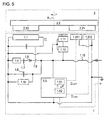
- FIG. 5 a further embodiment is shown, which differs from the previously described by a simplified circuit.
- the voltage pulse ⁇ of the pulse wire 1.1 no longer contributes to the power supply of the rotary encoder, but essentially serves only to control the switch 1.9.
- the circuit can be further simplified by omitting the buffer capacitor 1.6.
- the mentioned simplifications of the circuit are also applicable to the embodiments described below.
- the invention can also be implemented in an optical rotary encoder.
- a corresponding schematic circuit is in the FIG. 6 shown.
- the excitation circuit is now designed as a driver circuit 1.10 'for a light source 1.11', which serves as an emitter.
- the light from the light source 1.11 ' meets an optical graduation 2.21' and is modulated depending on the angular position of the shaft 2.1 or of the relative position of the graduation 2.21 'to photo elements 1.211', 1.212 '.
- the modulated light is received by the two photoelements 1.211 ', 1.212' and converted into electrical signals ⁇ 1.211 ' , ⁇ 1.212' .
- the photoelements 1.211 ', 1.212' are arranged geometrically such that the signals ⁇ 1.211 ' , ⁇ 1.212' are phase-shifted by 90 °.
- the rotary encoder is also in a second operating mode here, using the battery 1.7 as a voltage source. If the shaft 2.1, or the rotor 2, so here, the switch 1.9 remains open and the battery 1.7 is not charged. The position information P originally stored in the non-volatile memory 1.52 is retained.
- the pulse wire 1.1 As soon as the shaft 2.1 rotates and the magnet 2.23 approaches the pulse wire 1.1, the pulse wire 1.1 generates, as already described in the first exemplary embodiment, a voltage pulse ⁇ .
- the voltage pulse ⁇ triggers the closing of the switch 1.9, so that the battery 1.7, supported by the energy content of the voltage pulse II from the pulse wire 1.1, current u. a. to the driver circuit 1.10 'and the electronic circuit 1.5 outputs.
- the driver circuit 1.10 ' causes the light source 1.11' to emit a light pulse.
- ⁇ 1.211' of the relative position of the optical division 2.21 'to the photo elements 1211', 1,212 and 1,212 ⁇ 'of the photo elements 1211', produced 1.212 '.
- These signals ⁇ 1.211 ' , ⁇ 1.212' are then passed to the circuit 1.5 and processed there in the logic circuit 1.51, taking into account a direction detection algorithm.
- the logic circuit 1.51 then passes a position information P to a non-volatile memory 1.52 and stores it there. After the voltage pulse II has subsided again, the switch 1.9 opens again and the battery 1.7 is now no charge from.
- FIG. 7 another embodiment is shown.
- active receiver elements in the form of MR sensors 1.211 “, 1.212” are now arranged on the stator 1.
- a magnetic division track 2.21 " is located opposite these MR sensors 1.211", 1.212 ".
- This division track 2.21” can either consist of one piece of magnetizable material having a predetermined magnetization pattern, or it can consist of individual separate magnets.
- the MR sensors 1.211 “, 1.212” generate signals ⁇ 1.211 " , ⁇ 1.212” , which depend on the relative position between the code disk 2.2 and stator 1 are.
- the mode of operation is in case the external power supply is not available analogous to the examples described above. However, in this case, the electrical energy is also used for the operation of the MR sensors 1.211 “, 1.212", however, no electromagnetic field or light must be generated here.
- the occurrence of the voltage pulse II also for determining the angular position or relative position between the code plate 2.2 and stator 1 in the electronic circuit 1.5 are additionally taken into account.
- the number of detectors can be reduced.
Claims (12)
- Codeur rotatif comprenant un premier groupe de composants (1) et un deuxième groupe de composants (2), les groupes de composants (1, 2) étant disposés de manière à pouvoir effectuer une rotation relative l'un par rapport à l'autre autour d'un axe (A), et
le premier groupe de composants (1) présentant* un fil d'impulsion (1.1),* au moins un détecteur (1.211, 1.212 ; 1.211', 1.212' ; 1.211", 1.212") ainsi que* un circuit électronique (1.5) doté d'un circuit logique (1.51) et d'une mémoire non volatile (1.52),le deuxième groupe de composants (2) présentant* un aimant (2.23) et* au moins un élément de codage (2.21 ; 2.21' ; 2.21"),une impulsion de tension (II) pouvant être générée par le fil d'impulsion (1.1) en approchant l'aimant (2.23) du fil d'impulsion (1.1), et
suivant la position relative de l'élément de codage (2.21 ; 2.21' ; 2.21") par rapport à l'au moins un détecteur (1.211, 1.212 ; 1.211', 1.212' ; 1.211", 1.212"), un signal (Σ1.211, Σ1.222 ; Σ1.211', Σ1.222' ; Σ1.211", Σ1.222") pouvant être généré par celui-ci, une information de position (P) pouvant être déterminée par le circuit logique (1.51) en se basant sur le signal (Σ1.211, Σ1.222 ; Σ1.211', Σ1.222' ; Σ1.211", Σ1.222"), laquelle peut être enregistrée dans la mémoire non volatile (1.52), caractérisé en ce que
le premier groupe de composants (1) est configuré de telle sorte que
le circuit (1.5), déclenché par l'apparition de l'impulsion de tension (Π), peut être chargé avec une tension d'une source de tension (1.7), le fil d'impulsion (1.1) étant branché en parallèle avec la source de tension (1.7) de sorte que l'impulsion de tension (Π) du fil d'impulsion (1.1) contribue à l'alimentation en énergie du circuit (1.5), et le circuit (1.5) peut de nouveau être déconnecté de la source de tension (1.7) au plus tard après l'enregistrement de l'information de position (P) dans la mémoire non volatile (1.52). - Codeur rotatif selon la revendication 1, caractérisé en ce que le premier groupe de composants (1) comprend un émetteur (1.11 ; 1.11') par le biais duquel peut être généré un champ électromagnétique, lequel peut être modulé par l'au moins un élément de codage (2.21 ; 2.21'), de sorte que suivant la position relative de l'élément de codage (2.21 ; 2.21') par rapport à l'au moins un détecteur (1.211, 1.212 ; 1.211', 1.212'), un signal (Σ1.211, Σ1.222 ; Σ1.211', Σ1.222') peut être généré par celui-ci, le premier groupe de composants (1) étant configuré de telle sorte que l'émetteur (1.11 ; 1.11')* déclenché par l'apparition de l'impulsion de tension (Π), peut être chargé avec une tension d'une source de tension (1.7), et* peut de nouveau être déconnecté de la source de tension (1.7) au plus tard après l'enregistrement de l'information de position (P) dans la mémoire non volatile (1.52).
- Codeur rotatif selon la revendication 2, caractérisé en ce que l'émetteur (1.11) comprend un enroulement excitateur par le biais duquel peut être généré un champ électromagnétique et l'au moins un détecteur (1.211, 1.212) est réalisé sous la forme d'un enroulement récepteur.
- Codeur rotatif selon la revendication 2, caractérisé en ce que l'émetteur (1.11') comprend une source de lumière, et l'au moins un détecteur (1.211', 1.212') est réalisé sous la forme d'un élément photoélectrique.
- Codeur rotatif selon la revendication 1, caractérisé en ce que le premier groupe de composants (1) est configuré de telle sorte que l'au moins un détecteur (1.211", 1.212"), déclenché par l'apparition de l'impulsion de tension (Π), peut être chargé avec une tension d'une source de tension (1.7) et peut de nouveau être déconnecté de la source de tension (1.7).
- Codeur rotatif selon la revendication 5, caractérisé en ce que l'au moins un élément de codage (2.21") est réalisé sous la forme d'un aimant et l'au moins un détecteur (1.211", 1.212") est un élément MR ou à effet Hall.
- Procédé de fonctionnement d'un codeur rotatif, le codeur rotatif comprenant un premier groupe de composants (1) et un deuxième groupe de composants (2), et les groupes de composants (1, 2) étant disposés de manière à pouvoir effectuer une rotation relative l'un par rapport à l'autre autour d'un axe (A), et
le premier groupe de composants (1) présentant* un fil d'impulsion (1.1),* au moins un détecteur (1.211, 1.212 ; 1.211', 1.212' ; 1.211", 1.212") ainsi que* un circuit électronique (1.5) doté d'un circuit logique (1.51) et d'une mémoire non volatile (1.52),le deuxième groupe de composants (2) présentant* un aimant (2.23) et* au moins un élément de codage (2.21 ; 2.21' ; 2.21"),une impulsion de tension (Π) étant générée par le fil d'impulsion (1.1) en approchant l'aimant (2.23) du fil d'impulsion (1.1), et
suivant la position relative de l'élément de codage (2.21 ; 2.21' ; 2.21") par rapport à l'au moins un détecteur (1.211, 1.212 ; 1.211', 1.212' ; 1.211", 1.212"), un signal (Σ1.211, Σ1.222 ; Σ1.211', Σ1.222' ; Σ1.211", Σ1.222") étant généré par celui-ci, une information de position (P) étant déterminée par le circuit logique (1.51) en se basant sur le signal (Σ1.211, Σ1.222 ; Σ1.211', Σ1.222' ; Σ1.211", Σ1.222"), laquelle est enregistrée dans la mémoire non volatile (1.52), caractérisé en ce que le premier groupe de composants (1) est configuré de telle sorte que
le circuit (1.5), déclenché par l'apparition de l'impulsion de tension (Π), est chargé avec une tension d'une source de tension (1.7) et le fil d'impulsion (1.1) est branché en parallèle avec la source de tension (1.7) de sorte que l'impulsion de tension (II) du fil d'impulsion (1.1) contribue à l'alimentation en énergie du circuit (1.5), et le circuit (1.5) est de nouveau déconnecté de la source de tension (1.7) au plus tard après l'enregistrement de l'information de position (P) dans la mémoire non volatile (1.52). - Procédé selon la revendication 7, caractérisé en ce que le premier groupe de composants (1) comprend un émetteur (1.11 ; 1.11') par le biais duquel est généré un champ électromagnétique, lequel est modulé par l'au moins un élément de codage (2.21 ; 2.21'), de sorte que suivant la position relative de l'élément de codage (2.21 ; 2.21') par rapport à l'au moins un détecteur (1.211, 1.212 ; 1.211', 1.212'), un signal (Σ1.211, Σ1.222 ; Σ1.211', Σ1.222') est généré par celui-ci, l'apparition de l'impulsion de tension (Π) déclenchant le fait que l'émetteur (1.11 ; 1.11') est chargé avec une tension d'une source de tension (1.7), et l'émetteur (1.11 ; 1.11') est de nouveau déconnecté de la source de tension (1.7) au plus tard après l'enregistrement de l'information de position (P) dans la mémoire non volatile (1.52).
- Procédé selon la revendication 8, caractérisé en ce que l'émetteur (1.11) comprend un enroulement excitateur par le biais duquel est généré un champ électromagnétique et l'au moins un détecteur (1.211, 1.212) est réalisé sous la forme d'un enroulement récepteur.
- Procédé selon la revendication 8, caractérisé en ce que l'émetteur (1.11') comprend une source de lumière, et l'au moins un détecteur (1.211', 1.212') est réalisé sous la forme d'un élément photoélectrique.
- Procédé selon la revendication 7, caractérisé en ce que l'apparition de l'impulsion de tension (Π) déclenche le fait que l'au moins un détecteur (1.211", 1.212'') est chargé avec une tension d'une source de tension (1.7) et est ensuite de nouveau déconnecté de la source de tension (1.7).
- Procédé selon l'une des revendications 7 à 11, caractérisé en ce que l'au moins un élément de codage (2.21") est réalisé sous la forme d'un aimant et l'au moins un détecteur (1.211", 1.212") est un élément MR ou à effet Hall.
Applications Claiming Priority (1)
| Application Number | Priority Date | Filing Date | Title |
|---|---|---|---|
| DE102007007764A DE102007007764A1 (de) | 2007-02-16 | 2007-02-16 | Drehgeber und Verfahren zu dessen Betrieb |
Publications (3)
| Publication Number | Publication Date |
|---|---|
| EP1959240A2 EP1959240A2 (fr) | 2008-08-20 |
| EP1959240A3 EP1959240A3 (fr) | 2013-06-19 |
| EP1959240B1 true EP1959240B1 (fr) | 2014-06-04 |
Family
ID=39143936
Family Applications (1)
| Application Number | Title | Priority Date | Filing Date |
|---|---|---|---|
| EP07024089.0A Active EP1959240B1 (fr) | 2007-02-16 | 2007-12-12 | Encodeur et son procédé de fonctionnement |
Country Status (5)
| Country | Link |
|---|---|
| US (1) | US7439734B2 (fr) |
| EP (1) | EP1959240B1 (fr) |
| JP (1) | JP5142750B2 (fr) |
| CN (1) | CN101245982B (fr) |
| DE (1) | DE102007007764A1 (fr) |
Families Citing this family (18)
| Publication number | Priority date | Publication date | Assignee | Title |
|---|---|---|---|---|
| JP4896642B2 (ja) | 2006-09-12 | 2012-03-14 | Tdk株式会社 | 積層コンデンサ及び電子機器 |
| DE102008015837A1 (de) * | 2008-03-27 | 2009-10-01 | Dr. Johannes Heidenhain Gmbh | Positionsmessgerät und Verfahren zu dessen Betrieb |
| DE102009021081B4 (de) * | 2008-07-18 | 2017-07-06 | Asm Automation Sensorik Messtechnik Gmbh | Magnetischer Winkelsensor |
| DE102008046741A1 (de) * | 2008-09-11 | 2010-03-18 | Dr. Johannes Heidenhain Gmbh | Induktiver Positionssensor, damit ausgestattetes Messsystem und Verfahren zum Betrieb eines Positionssensors |
| CN102486383A (zh) * | 2010-12-06 | 2012-06-06 | 沈阳理工大学 | 一种电保持多圈绝对值编码器 |
| DE102011004348A1 (de) * | 2011-02-17 | 2012-08-23 | Beckhoff Automation Gmbh | Verfahren und Positionserfassungsvorrichtung zum Erfassen einer Position eines beweglichen Elements einer Antriebsvorrichtung |
| DE102012223037A1 (de) * | 2012-12-13 | 2014-06-18 | Dr. Johannes Heidenhain Gmbh | Induktive Positionsmesseinrichtung |
| DE102015203752A1 (de) * | 2015-03-03 | 2016-09-08 | Zf Friedrichshafen Ag | Sensorvorrichtung zum Erfassen einer Wählhebelposition und Wählhebelvorrichtung für ein Kraftfahrzeug |
| TWI588450B (zh) * | 2015-04-21 | 2017-06-21 | Murata Manufacturing Co | Encoder |
| CN108496061A (zh) * | 2016-01-18 | 2018-09-04 | 株式会社尼康 | 编码器装置、驱动装置、载置台装置以及机器人装置 |
| JP6773050B2 (ja) * | 2016-01-18 | 2020-10-21 | 株式会社ニコン | エンコーダ装置、駆動装置、ステージ装置、及びロボット装置 |
| DE102016202859B3 (de) * | 2016-02-24 | 2017-06-29 | Robert Bosch Gmbh | Drehwinkelsensor |
| DE102017123772B4 (de) * | 2017-10-12 | 2019-06-19 | Paul Tutzu | Elektromagnetisches Messsystem für die Erfassung von Länge und Winkel basierend auf dem Magnetoimpedanzeffekt |
| CN109211092B (zh) * | 2017-12-15 | 2019-06-21 | 重庆理工大学 | 一种基于交变电场的绝对式时栅角位移传感器 |
| EP3553336B1 (fr) * | 2018-04-10 | 2021-03-31 | Aktiebolaget SKF | Surveillance d'états |
| CN110864711B (zh) * | 2018-08-27 | 2022-03-11 | 台达电子工业股份有限公司 | 编码器及其位置检测方法 |
| DE102018220363A1 (de) * | 2018-11-27 | 2020-05-28 | Te Connectivity Germany Gmbh | Winkelmesssystem zur Bestimmung eines Winkels zwischen einem Rotor und einem gegenüberliegenden Stator |
| EP3702737B1 (fr) * | 2019-03-01 | 2021-05-12 | Dr. Johannes Heidenhain GmbH | Unité de balayage permettant de balayer une échelle d'angle ainsi que dispositif de mesure d'angle doté d'une telle unité de balayage |
Family Cites Families (11)
| Publication number | Priority date | Publication date | Assignee | Title |
|---|---|---|---|---|
| US4380928A (en) * | 1980-08-29 | 1983-04-26 | Aisin Seiki Company, Limited | Rotational angle sensor |
| JPH01184415A (ja) * | 1988-01-18 | 1989-07-24 | Yamaha Corp | 電源モニタ回路および該回路を内蔵したロータリエンコーダ |
| CN1020956C (zh) * | 1990-08-25 | 1993-05-26 | 中国科学院长春光学精密机械研究所 | 绝对式轴角编码器设计方法及编码器 |
| JPH0618281A (ja) * | 1992-06-30 | 1994-01-25 | Nikon Corp | 多回転アブソリュートエンコーダ |
| DE4407474C2 (de) * | 1994-03-07 | 2000-07-13 | Asm Automation Sensorik Messte | Drehwinkelsensor |
| JPH0843127A (ja) * | 1994-07-29 | 1996-02-16 | Sanyo Denki Co Ltd | 絶対位置検出装置 |
| CN2255038Y (zh) * | 1995-05-22 | 1997-05-28 | 中国科学技术大学 | 软磁齿轮式轴角编码器 |
| DE10320990A1 (de) * | 2003-05-09 | 2004-11-25 | Dr. Johannes Heidenhain Gmbh | Induktiver Drehwinkelsensor und damit ausgestatteter Drehgeber |
| DE102004062448A1 (de) * | 2004-06-18 | 2006-01-19 | Valeo Schalter Und Sensoren Gmbh | Lenkwinkelsensor |
| DE102005009489A1 (de) * | 2005-02-24 | 2006-08-31 | Volkswagen Ag | Elektronikbaugruppe für eine Positionserfassungseinrichtung mit einer Weckvorrichtung zum Verarbeiten eines Aufweck-Strompulses einer Wiegand-Spule |
| DE102006046531A1 (de) | 2006-09-29 | 2008-04-03 | Dr. Johannes Heidenhain Gmbh | Drehgeber und Verfahren zu dessen Betrieb |
-
2007
- 2007-02-16 DE DE102007007764A patent/DE102007007764A1/de not_active Withdrawn
- 2007-12-12 EP EP07024089.0A patent/EP1959240B1/fr active Active
-
2008
- 2008-02-15 JP JP2008033883A patent/JP5142750B2/ja active Active
- 2008-02-18 CN CN2008100807551A patent/CN101245982B/zh not_active Expired - Fee Related
- 2008-02-19 US US12/033,459 patent/US7439734B2/en not_active Expired - Fee Related
Also Published As
| Publication number | Publication date |
|---|---|
| US20080197838A1 (en) | 2008-08-21 |
| CN101245982A (zh) | 2008-08-20 |
| EP1959240A3 (fr) | 2013-06-19 |
| CN101245982B (zh) | 2012-04-18 |
| JP2008203259A (ja) | 2008-09-04 |
| DE102007007764A1 (de) | 2008-08-21 |
| EP1959240A2 (fr) | 2008-08-20 |
| JP5142750B2 (ja) | 2013-02-13 |
| US7439734B2 (en) | 2008-10-21 |
Similar Documents
| Publication | Publication Date | Title |
|---|---|---|
| EP1959240B1 (fr) | Encodeur et son procédé de fonctionnement | |
| EP1607720B1 (fr) | Capteur d'angle de braquage | |
| EP2221587B1 (fr) | Indicateur de position magnétique absolu | |
| EP2844955B1 (fr) | Capteur de rotation multi-tours autosuffisant en énergie et procédé de détermination sans ambiguïté la position d'un arbre capteur avec le capteur de rotation multi-tours | |
| EP1906153B1 (fr) | Encodeur et son procédé de fonctionnement | |
| EP0736183B1 (fr) | Dispositif de detection de mouvements rotatifs et angulaires | |
| EP2105713B1 (fr) | Appareil de mesure de position et son procédé de fonctionnement | |
| EP0852700B1 (fr) | Systeme de detection sans contact de la position d'un objet et utilisation dudit dispositif | |
| DE102009044542B3 (de) | Wälzlager mit einer Sensoreinheit | |
| EP2295938B1 (fr) | Encodeur à plusieurs rotations | |
| WO2006122945A1 (fr) | Systeme de detection de la vitesse de rotation d'une roue a securite intrinseque | |
| WO2002046702A1 (fr) | Codeur rotatif | |
| DE102017124542A1 (de) | Magnetfeldsensoranordnung und verfahren zum messen eines externen magnetfelds | |
| EP1408305A2 (fr) | Dispositif de mesure de l'angle absolu d'un arbre tournant | |
| EP3936828B1 (fr) | Système de capteur pour un entraînement | |
| DE102012008888A1 (de) | Energieautarker Multiturn-Drehgeber und Verfahren zur Ermittlung einer eindeutigen Position einer Geberwelle mit dem Multiturn-Drehgeber | |
| EP1802942B1 (fr) | Procede et dispositif de detection sans contact d'un angle de rotation | |
| DE102008046741A1 (de) | Induktiver Positionssensor, damit ausgestattetes Messsystem und Verfahren zum Betrieb eines Positionssensors | |
| DE10054470C2 (de) | Drehstellungsgeber zum Erfassen einer Drehstellung | |
| EP2309232B1 (fr) | Indicateur de position doté d'une détermination de position à rotation multiple | |
| DE10354469B4 (de) | Vorrichtung zum Messen des Drehwinkels eines Drehkörpers | |
| DE102018215783A1 (de) | Positionserfassungssystem und Verfahren zur Erfassung einer Bewegung einer Maschine | |
| EP1617180A1 (fr) | Détecteur de position et méthode pour déterminer la position d'un arbre rotatif | |
| EP1770001A2 (fr) | Système de capteur | |
| DE102017203676B4 (de) | Magnetischer absoluter Positionssensor |
Legal Events
| Date | Code | Title | Description |
|---|---|---|---|
| PUAI | Public reference made under article 153(3) epc to a published international application that has entered the european phase |
Free format text: ORIGINAL CODE: 0009012 |
|
| AK | Designated contracting states |
Kind code of ref document: A2 Designated state(s): AT BE BG CH CY CZ DE DK EE ES FI FR GB GR HU IE IS IT LI LT LU LV MC MT NL PL PT RO SE SI SK TR |
|
| AX | Request for extension of the european patent |
Extension state: AL BA HR MK RS |
|
| PUAL | Search report despatched |
Free format text: ORIGINAL CODE: 0009013 |
|
| AK | Designated contracting states |
Kind code of ref document: A3 Designated state(s): AT BE BG CH CY CZ DE DK EE ES FI FR GB GR HU IE IS IT LI LT LU LV MC MT NL PL PT RO SE SI SK TR |
|
| AX | Request for extension of the european patent |
Extension state: AL BA HR MK RS |
|
| RIC1 | Information provided on ipc code assigned before grant |
Ipc: G01D 5/245 20060101AFI20130513BHEP |
|
| 17P | Request for examination filed |
Effective date: 20131219 |
|
| RBV | Designated contracting states (corrected) |
Designated state(s): AT BE BG CH CY CZ DE DK EE ES FI FR GB GR HU IE IS IT LI LT LU LV MC MT NL PL PT RO SE SI SK TR |
|
| REG | Reference to a national code |
Ref country code: DE Ref legal event code: R079 Ref document number: 502007013160 Country of ref document: DE Free format text: PREVIOUS MAIN CLASS: G01D0005245000 Ipc: G01D0005347000 |
|
| AKX | Designation fees paid |
Designated state(s): AT BE BG CH CY CZ DE DK EE ES FI FR GB GR HU IE IS IT LI LT LU LV MC MT NL PL PT RO SE SI SK TR |
|
| GRAP | Despatch of communication of intention to grant a patent |
Free format text: ORIGINAL CODE: EPIDOSNIGR1 |
|
| RIC1 | Information provided on ipc code assigned before grant |
Ipc: G01D 5/245 20060101ALI20140207BHEP Ipc: G01D 5/347 20060101AFI20140207BHEP |
|
| INTG | Intention to grant announced |
Effective date: 20140307 |
|
| RIN1 | Information on inventor provided before grant (corrected) |
Inventor name: FISCHER, PETER |
|
| GRAS | Grant fee paid |
Free format text: ORIGINAL CODE: EPIDOSNIGR3 |
|
| GRAA | (expected) grant |
Free format text: ORIGINAL CODE: 0009210 |
|
| AK | Designated contracting states |
Kind code of ref document: B1 Designated state(s): AT BE BG CH CY CZ DE DK EE ES FI FR GB GR HU IE IS IT LI LT LU LV MC MT NL PL PT RO SE SI SK TR |
|
| REG | Reference to a national code |
Ref country code: GB Ref legal event code: FG4D Free format text: NOT ENGLISH |
|
| REG | Reference to a national code |
Ref country code: CH Ref legal event code: EP |
|
| REG | Reference to a national code |
Ref country code: AT Ref legal event code: REF Ref document number: 671326 Country of ref document: AT Kind code of ref document: T Effective date: 20140615 |
|
| REG | Reference to a national code |
Ref country code: IE Ref legal event code: FG4D Free format text: LANGUAGE OF EP DOCUMENT: GERMAN |
|
| REG | Reference to a national code |
Ref country code: DE Ref legal event code: R096 Ref document number: 502007013160 Country of ref document: DE Effective date: 20140717 |
|
| REG | Reference to a national code |
Ref country code: NL Ref legal event code: VDEP Effective date: 20140604 |
|
| PG25 | Lapsed in a contracting state [announced via postgrant information from national office to epo] |
Ref country code: LT Free format text: LAPSE BECAUSE OF FAILURE TO SUBMIT A TRANSLATION OF THE DESCRIPTION OR TO PAY THE FEE WITHIN THE PRESCRIBED TIME-LIMIT Effective date: 20140604 Ref country code: FI Free format text: LAPSE BECAUSE OF FAILURE TO SUBMIT A TRANSLATION OF THE DESCRIPTION OR TO PAY THE FEE WITHIN THE PRESCRIBED TIME-LIMIT Effective date: 20140604 Ref country code: CY Free format text: LAPSE BECAUSE OF FAILURE TO SUBMIT A TRANSLATION OF THE DESCRIPTION OR TO PAY THE FEE WITHIN THE PRESCRIBED TIME-LIMIT Effective date: 20140604 Ref country code: GR Free format text: LAPSE BECAUSE OF FAILURE TO SUBMIT A TRANSLATION OF THE DESCRIPTION OR TO PAY THE FEE WITHIN THE PRESCRIBED TIME-LIMIT Effective date: 20140905 |
|
| REG | Reference to a national code |
Ref country code: LT Ref legal event code: MG4D |
|
| PG25 | Lapsed in a contracting state [announced via postgrant information from national office to epo] |
Ref country code: LV Free format text: LAPSE BECAUSE OF FAILURE TO SUBMIT A TRANSLATION OF THE DESCRIPTION OR TO PAY THE FEE WITHIN THE PRESCRIBED TIME-LIMIT Effective date: 20140604 Ref country code: SE Free format text: LAPSE BECAUSE OF FAILURE TO SUBMIT A TRANSLATION OF THE DESCRIPTION OR TO PAY THE FEE WITHIN THE PRESCRIBED TIME-LIMIT Effective date: 20140604 |
|
| PG25 | Lapsed in a contracting state [announced via postgrant information from national office to epo] |
Ref country code: PT Free format text: LAPSE BECAUSE OF FAILURE TO SUBMIT A TRANSLATION OF THE DESCRIPTION OR TO PAY THE FEE WITHIN THE PRESCRIBED TIME-LIMIT Effective date: 20141006 Ref country code: CZ Free format text: LAPSE BECAUSE OF FAILURE TO SUBMIT A TRANSLATION OF THE DESCRIPTION OR TO PAY THE FEE WITHIN THE PRESCRIBED TIME-LIMIT Effective date: 20140604 Ref country code: ES Free format text: LAPSE BECAUSE OF FAILURE TO SUBMIT A TRANSLATION OF THE DESCRIPTION OR TO PAY THE FEE WITHIN THE PRESCRIBED TIME-LIMIT Effective date: 20140604 Ref country code: SK Free format text: LAPSE BECAUSE OF FAILURE TO SUBMIT A TRANSLATION OF THE DESCRIPTION OR TO PAY THE FEE WITHIN THE PRESCRIBED TIME-LIMIT Effective date: 20140604 Ref country code: RO Free format text: LAPSE BECAUSE OF FAILURE TO SUBMIT A TRANSLATION OF THE DESCRIPTION OR TO PAY THE FEE WITHIN THE PRESCRIBED TIME-LIMIT Effective date: 20140604 Ref country code: EE Free format text: LAPSE BECAUSE OF FAILURE TO SUBMIT A TRANSLATION OF THE DESCRIPTION OR TO PAY THE FEE WITHIN THE PRESCRIBED TIME-LIMIT Effective date: 20140604 |
|
| PG25 | Lapsed in a contracting state [announced via postgrant information from national office to epo] |
Ref country code: NL Free format text: LAPSE BECAUSE OF FAILURE TO SUBMIT A TRANSLATION OF THE DESCRIPTION OR TO PAY THE FEE WITHIN THE PRESCRIBED TIME-LIMIT Effective date: 20140604 Ref country code: IS Free format text: LAPSE BECAUSE OF FAILURE TO SUBMIT A TRANSLATION OF THE DESCRIPTION OR TO PAY THE FEE WITHIN THE PRESCRIBED TIME-LIMIT Effective date: 20141004 Ref country code: PL Free format text: LAPSE BECAUSE OF FAILURE TO SUBMIT A TRANSLATION OF THE DESCRIPTION OR TO PAY THE FEE WITHIN THE PRESCRIBED TIME-LIMIT Effective date: 20140604 |
|
| REG | Reference to a national code |
Ref country code: DE Ref legal event code: R097 Ref document number: 502007013160 Country of ref document: DE |
|
| PLBE | No opposition filed within time limit |
Free format text: ORIGINAL CODE: 0009261 |
|
| STAA | Information on the status of an ep patent application or granted ep patent |
Free format text: STATUS: NO OPPOSITION FILED WITHIN TIME LIMIT |
|
| PG25 | Lapsed in a contracting state [announced via postgrant information from national office to epo] |
Ref country code: IT Free format text: LAPSE BECAUSE OF FAILURE TO SUBMIT A TRANSLATION OF THE DESCRIPTION OR TO PAY THE FEE WITHIN THE PRESCRIBED TIME-LIMIT Effective date: 20140604 Ref country code: DK Free format text: LAPSE BECAUSE OF FAILURE TO SUBMIT A TRANSLATION OF THE DESCRIPTION OR TO PAY THE FEE WITHIN THE PRESCRIBED TIME-LIMIT Effective date: 20140604 |
|
| 26N | No opposition filed |
Effective date: 20150305 |
|
| REG | Reference to a national code |
Ref country code: DE Ref legal event code: R097 Ref document number: 502007013160 Country of ref document: DE Effective date: 20150305 |
|
| PG25 | Lapsed in a contracting state [announced via postgrant information from national office to epo] |
Ref country code: BE Free format text: LAPSE BECAUSE OF NON-PAYMENT OF DUE FEES Effective date: 20141231 |
|
| PG25 | Lapsed in a contracting state [announced via postgrant information from national office to epo] |
Ref country code: SI Free format text: LAPSE BECAUSE OF FAILURE TO SUBMIT A TRANSLATION OF THE DESCRIPTION OR TO PAY THE FEE WITHIN THE PRESCRIBED TIME-LIMIT Effective date: 20140604 Ref country code: LU Free format text: LAPSE BECAUSE OF FAILURE TO SUBMIT A TRANSLATION OF THE DESCRIPTION OR TO PAY THE FEE WITHIN THE PRESCRIBED TIME-LIMIT Effective date: 20141212 |
|
| REG | Reference to a national code |
Ref country code: CH Ref legal event code: PL |
|
| GBPC | Gb: european patent ceased through non-payment of renewal fee |
Effective date: 20141212 |
|
| REG | Reference to a national code |
Ref country code: IE Ref legal event code: MM4A |
|
| REG | Reference to a national code |
Ref country code: FR Ref legal event code: ST Effective date: 20150831 |
|
| PG25 | Lapsed in a contracting state [announced via postgrant information from national office to epo] |
Ref country code: LI Free format text: LAPSE BECAUSE OF NON-PAYMENT OF DUE FEES Effective date: 20141231 Ref country code: GB Free format text: LAPSE BECAUSE OF NON-PAYMENT OF DUE FEES Effective date: 20141212 Ref country code: CH Free format text: LAPSE BECAUSE OF NON-PAYMENT OF DUE FEES Effective date: 20141231 Ref country code: IE Free format text: LAPSE BECAUSE OF NON-PAYMENT OF DUE FEES Effective date: 20141212 |
|
| PG25 | Lapsed in a contracting state [announced via postgrant information from national office to epo] |
Ref country code: FR Free format text: LAPSE BECAUSE OF NON-PAYMENT OF DUE FEES Effective date: 20141231 |
|
| REG | Reference to a national code |
Ref country code: AT Ref legal event code: MM01 Ref document number: 671326 Country of ref document: AT Kind code of ref document: T Effective date: 20141212 |
|
| PG25 | Lapsed in a contracting state [announced via postgrant information from national office to epo] |
Ref country code: AT Free format text: LAPSE BECAUSE OF NON-PAYMENT OF DUE FEES Effective date: 20141212 Ref country code: MC Free format text: LAPSE BECAUSE OF FAILURE TO SUBMIT A TRANSLATION OF THE DESCRIPTION OR TO PAY THE FEE WITHIN THE PRESCRIBED TIME-LIMIT Effective date: 20140604 Ref country code: BG Free format text: LAPSE BECAUSE OF FAILURE TO SUBMIT A TRANSLATION OF THE DESCRIPTION OR TO PAY THE FEE WITHIN THE PRESCRIBED TIME-LIMIT Effective date: 20140604 |
|
| PG25 | Lapsed in a contracting state [announced via postgrant information from national office to epo] |
Ref country code: MT Free format text: LAPSE BECAUSE OF FAILURE TO SUBMIT A TRANSLATION OF THE DESCRIPTION OR TO PAY THE FEE WITHIN THE PRESCRIBED TIME-LIMIT Effective date: 20140604 Ref country code: TR Free format text: LAPSE BECAUSE OF FAILURE TO SUBMIT A TRANSLATION OF THE DESCRIPTION OR TO PAY THE FEE WITHIN THE PRESCRIBED TIME-LIMIT Effective date: 20140604 Ref country code: HU Free format text: LAPSE BECAUSE OF FAILURE TO SUBMIT A TRANSLATION OF THE DESCRIPTION OR TO PAY THE FEE WITHIN THE PRESCRIBED TIME-LIMIT; INVALID AB INITIO Effective date: 20071212 |
|
| PGFP | Annual fee paid to national office [announced via postgrant information from national office to epo] |
Ref country code: DE Payment date: 20231214 Year of fee payment: 17 |