EP1617180A1 - Détecteur de position et méthode pour déterminer la position d'un arbre rotatif - Google Patents
Détecteur de position et méthode pour déterminer la position d'un arbre rotatif Download PDFInfo
- Publication number
- EP1617180A1 EP1617180A1 EP04016309A EP04016309A EP1617180A1 EP 1617180 A1 EP1617180 A1 EP 1617180A1 EP 04016309 A EP04016309 A EP 04016309A EP 04016309 A EP04016309 A EP 04016309A EP 1617180 A1 EP1617180 A1 EP 1617180A1
- Authority
- EP
- European Patent Office
- Prior art keywords
- magnet
- microcontroller
- sensor unit
- sensor
- transmitter according
- Prior art date
- Legal status (The legal status is an assumption and is not a legal conclusion. Google has not performed a legal analysis and makes no representation as to the accuracy of the status listed.)
- Granted
Links
- 238000000034 method Methods 0.000 title claims abstract description 16
- 230000005291 magnetic effect Effects 0.000 claims abstract description 31
- 235000014676 Phragmites communis Nutrition 0.000 claims description 26
- 238000001514 detection method Methods 0.000 claims description 15
- 238000011156 evaluation Methods 0.000 claims description 9
- 238000012544 monitoring process Methods 0.000 claims description 6
- 230000005540 biological transmission Effects 0.000 claims description 4
- 230000001960 triggered effect Effects 0.000 claims description 4
- 230000002618 waking effect Effects 0.000 claims description 4
- 238000001914 filtration Methods 0.000 claims description 3
- 239000003302 ferromagnetic material Substances 0.000 claims description 2
- 230000006870 function Effects 0.000 abstract description 2
- 230000008901 benefit Effects 0.000 description 16
- 238000005259 measurement Methods 0.000 description 8
- 230000007613 environmental effect Effects 0.000 description 6
- 241001136792 Alle Species 0.000 description 3
- 238000010276 construction Methods 0.000 description 3
- 238000010586 diagram Methods 0.000 description 3
- 238000000926 separation method Methods 0.000 description 3
- 239000000428 dust Substances 0.000 description 2
- 230000003993 interaction Effects 0.000 description 2
- 230000007246 mechanism Effects 0.000 description 2
- 230000003287 optical effect Effects 0.000 description 2
- 230000035939 shock Effects 0.000 description 2
- HBBGRARXTFLTSG-UHFFFAOYSA-N Lithium ion Chemical compound [Li+] HBBGRARXTFLTSG-UHFFFAOYSA-N 0.000 description 1
- 230000003213 activating effect Effects 0.000 description 1
- 230000006399 behavior Effects 0.000 description 1
- 230000008859 change Effects 0.000 description 1
- 238000009833 condensation Methods 0.000 description 1
- 230000005494 condensation Effects 0.000 description 1
- 238000011109 contamination Methods 0.000 description 1
- 238000001816 cooling Methods 0.000 description 1
- 238000005260 corrosion Methods 0.000 description 1
- 230000007797 corrosion Effects 0.000 description 1
- 230000001419 dependent effect Effects 0.000 description 1
- 238000013461 design Methods 0.000 description 1
- 230000000694 effects Effects 0.000 description 1
- 238000005538 encapsulation Methods 0.000 description 1
- 238000005516 engineering process Methods 0.000 description 1
- 230000002349 favourable effect Effects 0.000 description 1
- 239000004519 grease Substances 0.000 description 1
- 238000009413 insulation Methods 0.000 description 1
- 229910001416 lithium ion Inorganic materials 0.000 description 1
- -1 moisture Substances 0.000 description 1
- 238000013021 overheating Methods 0.000 description 1
- 238000009420 retrofitting Methods 0.000 description 1
- 238000012546 transfer Methods 0.000 description 1
Images


Classifications
-
- G—PHYSICS
- G01—MEASURING; TESTING
- G01D—MEASURING NOT SPECIALLY ADAPTED FOR A SPECIFIC VARIABLE; ARRANGEMENTS FOR MEASURING TWO OR MORE VARIABLES NOT COVERED IN A SINGLE OTHER SUBCLASS; TARIFF METERING APPARATUS; MEASURING OR TESTING NOT OTHERWISE PROVIDED FOR
- G01D5/00—Mechanical means for transferring the output of a sensing member; Means for converting the output of a sensing member to another variable where the form or nature of the sensing member does not constrain the means for converting; Transducers not specially adapted for a specific variable
- G01D5/12—Mechanical means for transferring the output of a sensing member; Means for converting the output of a sensing member to another variable where the form or nature of the sensing member does not constrain the means for converting; Transducers not specially adapted for a specific variable using electric or magnetic means
- G01D5/14—Mechanical means for transferring the output of a sensing member; Means for converting the output of a sensing member to another variable where the form or nature of the sensing member does not constrain the means for converting; Transducers not specially adapted for a specific variable using electric or magnetic means influencing the magnitude of a current or voltage
- G01D5/142—Mechanical means for transferring the output of a sensing member; Means for converting the output of a sensing member to another variable where the form or nature of the sensing member does not constrain the means for converting; Transducers not specially adapted for a specific variable using electric or magnetic means influencing the magnitude of a current or voltage using Hall-effect devices
- G01D5/145—Mechanical means for transferring the output of a sensing member; Means for converting the output of a sensing member to another variable where the form or nature of the sensing member does not constrain the means for converting; Transducers not specially adapted for a specific variable using electric or magnetic means influencing the magnitude of a current or voltage using Hall-effect devices influenced by the relative movement between the Hall device and magnetic fields
Definitions
- the invention relates to a position sensor and a method for determining a position of a rotatable shaft.
- the prior art (DE 198 49 108 C2) includes a rotary encoder with a sensor shaft which carries a first encoder for a single-turn measurement and a second encoder for a multi-turn measurement, wherein the Multiturncodiersay an evaluation is associated, which signals triggered by sensors a logic module and a downstream counter module which converts the signals into counter pulses.
- This belonging to the prior art rotary encoder has the disadvantage that in each case a coding disc with an associated sensor and electronics is required for the single-turn measurement and multi-turn measurement.
- this belonging to the prior art rotary encoder has the disadvantage that the sensors for counting the full revolutions simultaneously take on the function of a wake-up device for the logic module. This has the disadvantage that the alarm device requires filtering.
- This belonging to the prior art rotary encoder also has the disadvantage that the encoder shaft is guided in a housing in which the coding disc is arranged with the associated sensors and electronics.
- This embodiment has the disadvantage that the encoder shaft on the one hand must be mounted in the housing, that is, it is a complex storage required. On the other hand, an exact adjustment must be made, and the housing may not be tight against environmental influences.
- the technical problem underlying the invention is to provide a position sensor for determining a position of a rotatable shaft having a simple and inexpensive structure.
- a position sensor is to be specified, which is easy to assemble and is resistant to environmental influences.
- a method for determining a position of a rotatable shaft is to be specified, which can be carried out with a low-cost position sensor.
- the position sensor according to the invention for determining a position of a rotatable shaft with a sensor unit is constructed so that only one arranged on a shaft to be monitored magnet is provided for the position detection, the position sensor is used as a single-turn and simultaneously as a multi-turn unit has the position sensor according to the invention a very simple and inexpensive construction.
- an AMR sensor unit anisotropic magnetoresistance (anisotropic magnetoresistance)
- GMR sensor units giant magnetoresistance
- the position sensor is constructed such that the AMR sensor unit is arranged in a closed housing, and that the sensor unit is arranged opposite the housing outside of the housing, the magnet in or on the shaft to be monitored.
- Particularly advantageous position encoder according to the invention can be used as a rotary encoder for gates.
- other applications are conceivable.
- the position sensor on a magnet which is formed as a diametrically magnetized magnet.
- This magnet is assigned to the AMR sensor unit, that is, advantageously arranged opposite one another.
- a microcontroller is provided. The microcontroller and the sensor unit are provided for evaluating the magnetic field of the magnet.
- the sensor unit is advantageously designed as a two-part AMR sensor or the sensor unit has two AMR sensors.
- the microcontroller is activated only during the measurement times.
- a controlled by the magnet alarm device is provided for waking the microcontroller.
- the alarm device advantageously has at least one signal generator triggered by the magnetic field of the magnet.
- the signal generator may be formed, for example, as a reed switch or Hall element.
- one to three reed switches or Hall elements are provided. Since the power consumption of Hall elements is relatively high, it is possible to use Hall elements for a single-turn solution in which an external voltage is used permanently.
- At least one battery or at least one accumulator for supplying the microcontroller and the alarm device is provided.
- the at least one battery or the at least one rechargeable battery can supply the microcontroller and at least temporarily the AMR sensor unit, the comparators and the wake-up device with voltage.
- the alarm device is designed as a high-impedance resistors powered by the battery alarm.
- the position transmitter has a low power consumption during battery operation, because essentially only the high-impedance wake-up device is powered by the battery and the RAM content of the microcontroller is buffered.
- the position sensor according to the invention has at least one threshold value switch for digitizing the sine and cosine signals of the AMR sensor unit.
- the threshold value switch can be designed, for example, as a comparator.
- the microcontroller is advantageously designed as a microcontroller having power-saving features.
- an external power supply is advantageously provided.
- a parameter memory is advantageously provided so that various parameters are stored in case of power failure and, for example, gate positions (start and end position) do not have to be re-recorded.
- a temperature sensor is advantageously provided to ensure that in particular the electronic parts are not overheated.
- the AMR sensor unit is arranged in a closed housing, and the sensor unit is arranged opposite to the outside of the housing, the magnet in or on the shaft to be monitored.
- a separation of the encoder shaft is made by the sensor unit, so that the sensor unit is encapsulated and protected against environmental influences disposed in the housing.
- One implementation of the encoder shaft in the housing is not provided according to this embodiment.
- the magnet is arranged in a magnetic carrier which receives the end of the shaft to be monitored.
- the magnetic carrier can be plugged, for example, on the shaft to be monitored and fixed there.
- the housing in the region of the AMR sensor unit on a magnetic carrier at least partially receiving recess.
- This recess has the advantage that the arrangement of the encoder shaft with the magnet or the magnet carrier is set relatively clear by the arranged on the encoder shaft magnet or magnetic carrier is disposed in the recess. The fact that the sensor unit is arranged in the region of the recess, the magnet, when it is also disposed in the recess, automatically arranged opposite to the sensor unit.
- the magnetic carrier is advantageously arranged contactlessly in the recess.
- This embodiment has the advantage that the assembly is very simple, since it is only necessary to ensure that the magnet carrier is arranged in the recess. An exact alignment of the encoder shaft with the magnetic carrier is not required.
- the encoder shaft receiving magnetic carrier is mounted by means of at least one ball bearing in the recess.
- the ball bearing is very simple in this case, since the requirements for storage are not very high.
- the magnetic carrier is advantageously designed as a magnetic carrier which can be adapted to the shaft to be monitored. Characterized in that the magnetic carrier can be arranged on the shaft in a simple manner, an equipping or retrofitting a sensor shaft with the position sensor according to the invention in a very simple manner is possible.
- a very strong magnet for example with a magnetic field of at least fifty millitesla (mT) is used.
- the position sensor according to the invention has a relatively large tolerance range in the interaction between magnet and sensor.
- the AMR sensor is operated in saturation, so that a very small influence by external fields occurs.
- the housing is advantageously made of plastic. As a result, the housing can be manufactured very inexpensively. It is also possible to use another non-ferromagnetic material.
- the device according to the invention has the advantage that the housing, if it is made of plastic, is inexpensive and can be produced in complex shapes. It is corrosion resistant, has a low weight and a high density. In addition, it has the advantage that a poor heat transfer, for example, from a hot drive to electronics is present.
- a ball bearing is provided for mounting the magnet carrier in the recess of the housing, a favorable ball bearing can be used since no precision requirement is placed on the ball bearing.
- Another advantage of the position sensor according to the invention is that the encapsulation of the sensor unit no influence of dust, moisture, grease, oil and the like is present.
- the non-contact detection of revolutions also has the advantage that high speeds can be detected, and that a high mechanical life is achieved even in harsh environments.
- Another advantage of the invention is that when providing a housing cover this can also be opened “in the field", since the electronics is insensitive to contamination, moisture and so on. This gives the advantage that parts of the sensor unit or, for example, a battery is easily replaceable without additional mechanical effort. Furthermore, terminals can be plugged inside the housing so that no expensive and sealed special plug must be used.
- the position sensor according to the invention is preferably used for detecting gate positions. This may be the design of the shaft to the direct motor shaft (up to 6000 revolutions per minute), the transmission output shaft or the Torwelle or a specially mounted for position detection on the drive or the door mechanism special shaft.
- the inventive method for determining a position of a rotatable shaft with the position sensor according to the invention is generated with a diametrically magnetized magnet in a two-part AMR sensor or in two AMR sensors signals such that the output signals of the AMR sensor unit sine and cosine signals be obtained that the sine and cosine signals are digitized and that these signals from a microcontroller with respect to the detection and evaluation of the rotation angle for detection, filtering and evaluation of the number of revolutions to detect the direction of rotation and / or data transmission of the rotation angle and the number of revolutions are processed to a higher-level control.
- the AMR sensors or the two-part AMR sensor output voltages that pass through a sine or cosine shape twice over the entire angle of rotation of the magnet.
- the threshold value switches, for example the comparators, evaluate the voltage signals digitally. They each switch at the zero crossings of the voltages.
- the at least one signal switch of the wake-up device for the microcontroller is also actuated.
- the microcontroller switches automatically after evaluation of the signals in a sleep mode.
- the microcontroller awakens, it advantageously activates the AMR sensor unit and the at least one threshold value transmitter.
- the method according to the invention is characterized in that the position information is derived exclusively from the signals of the AMR sensor unit.
- the number of revolutions is advantageously determined on the basis of the zero crossings of the sine and cosine signals of the AMR sensor unit.
- the position sensor according to the invention and the method according to the invention have the advantage that due to the AMR sensor unit and the diametrically magnetized magnet, the sensor unit dissolves 180 ° revolutions of the magnet.
- an analog / digital resolution of the microcontroller for 180 ° can be used. For example, 12 bits are used for 180 ° instead of 360 ° for conventional coding discs.
- the resolution for one full revolution is thus for example 13 bits, namely the resolution of the ADC (for example 12 bits) plus 1 bit.
- the AMR sensor technology allows higher tolerances in the distance between the magnet and the sensor. As a result, a bearingless and non-contact embodiment for a door builder is practicable.
- the direction of the magnetic field is measured instead of the field strength. This gives the advantage that the influence of external fields is lower, and that larger distances can be evaluated without the influence of interference fields, for example in the millimeter range compared to 1/10 millimeter range.
- the magnetoresistive sensor unit has the advantage over optical disks that a mechanical separation between the sensor electronics and the position transmitter is possible. This gives the possibility of the housing To seal, and obtained by the bearing according to the invention variant of the magnetic carrier in the recess of the housing an inexpensive mechanism.
- the sensor unit which is encapsulated in the housing, is shielded against environmental influences, for example against condensation, against dust, shock and vibration and so on, above all during operation.
- the position sensor according to the invention has a low power consumption, the multi-turn signals can be derived from the single-turn sensor.
- optical systems due to the high power consumption, a battery-powered acquisition can only be realized over very short periods or only by means of very large batteries.
- the magnetic field of the magnet mounted on the shaft to be monitored is evaluated by the two-part AMR sensor or by the two AMR sensors which generate sine and cosine signals and by two reed switch contacts.
- the position information is derived here exclusively from the signals of the AMR sensor.
- the 180 ° monitoring based on analog value acquisition is only active as long as the entire device is powered by an external voltage.
- the number of revolutions is determined by the zero crossings of the sine and cosine signals. If the external supply voltage is removed, a backup battery is activated by the microcontroller. This supplies the microcontroller and a wake-up circuit, consisting advantageously of two reed switches, which are powered by high-impedance resistors of the battery.
- the reed switches are activated or deactivated in certain positions of the magnet, for example each about 15 ° before and after the zero crossings of sine and cosine.
- Each switching edge wakes up the permanently connected microcontroller.
- This in turn activates for a short time, for example 100 microseconds, the AMR sensor and a two-stage comparator stage.
- the comparator outputs in turn identify the position of the magnet to the sensor in 45 ° increments.
- the counter reading can now be determined.
- a plausibility check can be made on the timing of the signals, that is, on the history and the switching state of the reed contacts. This has the advantage that one is not dependent on the high-impedance bouncing signals of the reed switch.
- Fig. 1 shows a position sensor (1) with a housing (2), which is completely closed and made of plastic. Only a sealed cable entry (3) for a cable (4) is provided.
- a circuit board (5) is arranged, which carries an AMR sensor unit (6).
- a recess (7) is provided in the housing (2), in which a magnet carrier (8) with a magnet (9) arranged in the magnet carrier (8) is mounted without contact.
- the magnet carrier (8) is arranged on a shaft (10) whose number of revolutions is to be detected.
- the magnet carrier (8) is arranged without contact in the recess (7).
- a tolerance is possible in the contactless mounting of the magnetic carrier (8) in the recess (7).
- the axial distance (A) with a magnetic field of 50 millitesla (mT) up to five millimeters and the radial distance (B) up to one millimeter.
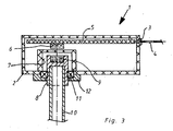
- Fig. 3 shows the position sensor (1). Like parts are provided with the reference numerals used in FIG.
- a ball bearing (11) is additionally arranged, which is fastened via a retaining plate (12) on the housing.
- the arrangement of the ball bearing (11) can be used in this embodiment of the position sensor (1) in a simple manner, a GMR sensor unit (6), since the required tolerances are maintained by the ball bearing (11).
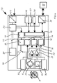
- Fig. 4 shows a block diagram of the electronics.
- the electronics (13) of the position sensor (1) has a highly integrated microcontroller (14), in turn, the components low-power CPU (15), interrupt controlled wake-up device (16), digital counter input (17), high-resolution ADC (18) with integrated amplifiers and offset determination (amplifiers could also be located outside the CPU), external supply power fail detection (19) and switching signal (20) for activating the sensor unit (6) and comparator stages (21, 22) during battery supply contains.
- the sensor unit (6) has 90 ° offset measuring bridges (23, 24) with two output signals for sine and cosine.
- the diametrically magnetized magnet (9) is arranged, which is rotatably mounted in the direction of the double arrow (C).
- the electronics (13) has a supply input (25) for an external supply, preferably between 10 and 30 volts with corresponding filter components.
- a voltage supply (26) is provided, preferably of five volts, and an undervoltage detection of the external supply, which generates a signal for switching to battery operation.
- a parameter memory (27) serves to store commissioning positions and the like. However, depending on the battery concept, the parameter memory is not absolutely necessary.
- a temperature sensor (28) is provided for monitoring the sensor internal temperature, since, for example, the limit temperature of the electronic components and in particular a lithium-ion battery (29) must not be exceeded. The temperature is transmitted via interface to the higher-level control. This can then, for example, the engine, if it is responsible for the overheating, shut down for a cooling period.
- a monitoring unit (30) is provided for monitoring the battery voltage. This is transmitted as diagnostic value to the higher-level controller. There it is evaluated and gives the operator a message that the battery is low and should be replaced.
- an interface (31) to the higher-level controller (32) is provided. It can be around An inexpensive RS485 serial asynchronous interface.
- the comparators (21, 22) are provided for digitizing the sine and cosine signals of the corresponding AMR sensors. These switch each at the zero crossing of the signals.
- the comparators (21, 22) are woken up by the microcontroller (14) during battery operation or the supply is switched on via the microcontroller (14).
- the AMR signals can additionally be evaluated via the ADC (18) of the microcontroller (14). However, the ADC (18) requires additional power and an initialization phase, so that the life of the battery (29) is shortened.
- the electronics (13) has reed contacts (33, 34) with high resistance.
- the first reed contact (33) is provided for the sine signal and the second reed contact (34) for the cosine signal.
- the reed contacts (33, 34) Depending on the mechanical position of the magnet (9), the reed contacts (33, 34) generate a switching edge, which in turn wakes up the microcontroller (14) sleeping in battery mode and activates it to count the interference-free comparator signals.
- the switching behavior of the reed contacts is determined by the mechanical positioning on the PCB.
- the position (arrangement) of the reed switch (33, 34) to the position of the AMR sensor (6) plays an essential role.
- a changeover switch (35) is provided between the battery supply and the external supply (25).
- the control of the switching (35) can be done either automatically based on the lack of external power supply or directly from the microcontroller (14).
- a controlled by the microcontroller switch (36) is provided for the supply of the AMR sensors (6) and the comparators (21, 22).
- the magnet (9) rotates through 360 °.
- the two AMR sensors in the sensor unit (6) output voltages which, viewed over the entire angle of rotation of the magnet (9), pass through a sine or cosine shape twice in each case.
- the comparators (21, 22) evaluate the voltage signals digitally. These signals are designated in Fig. 5 with Comp cosine and Comp sine.
- the comparators (21, 22) switch each at the zero crossings of the voltages.
- the signals (alarm 1, alarm 2) are generated by the reed switches (33, 34).
- the microcontroller (14) is awakened during battery operation of each switching edge of the reed switch (33, 34) and can then decide based on the evaluation of the comparator signals, whether it is a false trip or if the magnet (9) was further rotated. Here, the time between the flanks does not matter. There can be hours in between.
- the microcontroller (14), once woken up, is able to detect a "clean" signal from the comparators (21, 22) and can then decide from the history of the signals whether it counts backwards or forwards. If, for example, the microcontroller is woken up by interference pulses on the high-impedance reed signals, that is, without the magnet actually being rotated further, it merely controls the comparator signals without it continuing to count.
- These measurement cycles may include a multiple measurement for signal stability and signal reliability.
- the advantage of the position sensor (1) according to the invention is that a very long service life is achieved with the position sensor.
Landscapes
- Physics & Mathematics (AREA)
- General Physics & Mathematics (AREA)
- Measurement Of Length, Angles, Or The Like Using Electric Or Magnetic Means (AREA)
- Transmission And Conversion Of Sensor Element Output (AREA)
- Replacement Of Web Rolls (AREA)
- Vehicle Body Suspensions (AREA)
Priority Applications (4)
| Application Number | Priority Date | Filing Date | Title |
|---|---|---|---|
| DE502004005020T DE502004005020D1 (de) | 2004-07-12 | 2004-07-12 | Positionsgeber sowie Verfahren zur Bestimmung einer Position einer drehbaren Welle |
| EP04016309A EP1617180B1 (fr) | 2004-07-12 | 2004-07-12 | Détecteur de position et méthode pour déterminer la position d'un arbre rotatif |
| AT04016309T ATE373813T1 (de) | 2004-07-12 | 2004-07-12 | Positionsgeber sowie verfahren zur bestimmung einer position einer drehbaren welle |
| US11/176,779 US7466125B2 (en) | 2004-07-12 | 2005-07-07 | Position transmitter and method for determining a position of a rotating shaft |
Applications Claiming Priority (1)
| Application Number | Priority Date | Filing Date | Title |
|---|---|---|---|
| EP04016309A EP1617180B1 (fr) | 2004-07-12 | 2004-07-12 | Détecteur de position et méthode pour déterminer la position d'un arbre rotatif |
Publications (2)
| Publication Number | Publication Date |
|---|---|
| EP1617180A1 true EP1617180A1 (fr) | 2006-01-18 |
| EP1617180B1 EP1617180B1 (fr) | 2007-09-19 |
Family
ID=34925711
Family Applications (1)
| Application Number | Title | Priority Date | Filing Date |
|---|---|---|---|
| EP04016309A Expired - Lifetime EP1617180B1 (fr) | 2004-07-12 | 2004-07-12 | Détecteur de position et méthode pour déterminer la position d'un arbre rotatif |
Country Status (3)
| Country | Link |
|---|---|
| EP (1) | EP1617180B1 (fr) |
| AT (1) | ATE373813T1 (fr) |
| DE (1) | DE502004005020D1 (fr) |
Cited By (8)
| Publication number | Priority date | Publication date | Assignee | Title |
|---|---|---|---|---|
| DE102006035120A1 (de) * | 2006-07-28 | 2008-01-31 | Infineon Technologies Ag | Schaltungsanordnung zum Erfassen eines Drehwinkels einer Welle |
| WO2009047508A2 (fr) | 2007-10-11 | 2009-04-16 | Dall Production Aps | Codeur rotatif |
| DE102008042795A1 (de) * | 2008-10-13 | 2010-04-15 | Robert Bosch Gmbh | Vorrichtung zur Erfassung eines Drehwinkels eines drehbaren Teils |
| EP2878929A1 (fr) * | 2013-11-28 | 2015-06-03 | Dr. Johannes Heidenhain GmbH | Encodeur à plusieurs rotations |
| CN107918331A (zh) * | 2017-12-26 | 2018-04-17 | 福州普贝斯智能科技有限公司 | 一种低功耗带隔离的rs485被动唤醒装置及方法 |
| EP3361221A1 (fr) * | 2017-02-13 | 2018-08-15 | Marantec Antriebs- und Steuerungstechnik GmbH & Co. KG. | Capteur de détermination de position d'un système d'entraînement |
| US11428544B2 (en) | 2019-06-03 | 2022-08-30 | Honeywell International Inc. | Position sensor with wake up function |
| EP4242594A1 (fr) * | 2022-03-09 | 2023-09-13 | Baumer Germany GmbH & Co. KG | Capteur de rotation |
Families Citing this family (1)
| Publication number | Priority date | Publication date | Assignee | Title |
|---|---|---|---|---|
| DE102022119074A1 (de) | 2022-07-29 | 2024-02-01 | Feig Electronic Gmbh | Antriebsvorrichtung zum Bewegen einer Verdunkelungs-, Verstell- oder Verschließeinrichtung |
Citations (5)
| Publication number | Priority date | Publication date | Assignee | Title |
|---|---|---|---|---|
| EP0550794A2 (fr) * | 1991-11-30 | 1993-07-14 | IVO IRION & VOSSELER GMBH & CO. | Codeur de rotation avec détection de valeur absolue de position |
| EP0995974A1 (fr) * | 1998-10-24 | 2000-04-26 | Fritz Kübler GmbH Zähl-und Sensortechnik | Détecteur de rotation |
| US20010056333A1 (en) * | 2000-05-06 | 2001-12-27 | Klaus Dietmayer | Arrangement for angle measurements |
| US6578417B1 (en) * | 1999-09-15 | 2003-06-17 | Mannesmann Vdo Ag | Filling level sensor |
| DE10250319A1 (de) * | 2002-10-29 | 2003-10-30 | Bosch Gmbh Robert | Einrichtung zur Erfassung der Rotation einer Welle und GMR-Schichtsystem |
-
2004
- 2004-07-12 EP EP04016309A patent/EP1617180B1/fr not_active Expired - Lifetime
- 2004-07-12 AT AT04016309T patent/ATE373813T1/de not_active IP Right Cessation
- 2004-07-12 DE DE502004005020T patent/DE502004005020D1/de not_active Expired - Lifetime
Patent Citations (5)
| Publication number | Priority date | Publication date | Assignee | Title |
|---|---|---|---|---|
| EP0550794A2 (fr) * | 1991-11-30 | 1993-07-14 | IVO IRION & VOSSELER GMBH & CO. | Codeur de rotation avec détection de valeur absolue de position |
| EP0995974A1 (fr) * | 1998-10-24 | 2000-04-26 | Fritz Kübler GmbH Zähl-und Sensortechnik | Détecteur de rotation |
| US6578417B1 (en) * | 1999-09-15 | 2003-06-17 | Mannesmann Vdo Ag | Filling level sensor |
| US20010056333A1 (en) * | 2000-05-06 | 2001-12-27 | Klaus Dietmayer | Arrangement for angle measurements |
| DE10250319A1 (de) * | 2002-10-29 | 2003-10-30 | Bosch Gmbh Robert | Einrichtung zur Erfassung der Rotation einer Welle und GMR-Schichtsystem |
Cited By (13)
| Publication number | Priority date | Publication date | Assignee | Title |
|---|---|---|---|---|
| DE102006035120A1 (de) * | 2006-07-28 | 2008-01-31 | Infineon Technologies Ag | Schaltungsanordnung zum Erfassen eines Drehwinkels einer Welle |
| WO2009047508A2 (fr) | 2007-10-11 | 2009-04-16 | Dall Production Aps | Codeur rotatif |
| DE102008042795A1 (de) * | 2008-10-13 | 2010-04-15 | Robert Bosch Gmbh | Vorrichtung zur Erfassung eines Drehwinkels eines drehbaren Teils |
| US8890515B2 (en) | 2008-10-13 | 2014-11-18 | Robert Bosch Gmbh | Device for detecting a rotational angle of a rotatable part |
| EP2878929A1 (fr) * | 2013-11-28 | 2015-06-03 | Dr. Johannes Heidenhain GmbH | Encodeur à plusieurs rotations |
| US10203230B2 (en) | 2013-11-28 | 2019-02-12 | Dr. Johannes Heidenhain Gmbh | Multiturn rotary encoders |
| EP3361221A1 (fr) * | 2017-02-13 | 2018-08-15 | Marantec Antriebs- und Steuerungstechnik GmbH & Co. KG. | Capteur de détermination de position d'un système d'entraînement |
| CN107918331A (zh) * | 2017-12-26 | 2018-04-17 | 福州普贝斯智能科技有限公司 | 一种低功耗带隔离的rs485被动唤醒装置及方法 |
| CN107918331B (zh) * | 2017-12-26 | 2023-04-25 | 福州普贝斯智能科技有限公司 | 一种低功耗带隔离的rs485被动唤醒装置及方法 |
| US11428544B2 (en) | 2019-06-03 | 2022-08-30 | Honeywell International Inc. | Position sensor with wake up function |
| EP3748304B1 (fr) * | 2019-06-03 | 2023-11-15 | Honeywell International Inc. | Capteur de position doté d'une fonction de réveil |
| EP4242594A1 (fr) * | 2022-03-09 | 2023-09-13 | Baumer Germany GmbH & Co. KG | Capteur de rotation |
| DE102022000816A1 (de) | 2022-03-09 | 2023-09-14 | Baumer Germany Gmbh & Co. Kg | Drehgeber |
Also Published As
| Publication number | Publication date |
|---|---|
| ATE373813T1 (de) | 2007-10-15 |
| EP1617180B1 (fr) | 2007-09-19 |
| DE502004005020D1 (de) | 2007-10-31 |
Similar Documents
| Publication | Publication Date | Title |
|---|---|---|
| EP1959240B1 (fr) | Encodeur et son procédé de fonctionnement | |
| US7466125B2 (en) | Position transmitter and method for determining a position of a rotating shaft | |
| EP0995974B1 (fr) | Détecteur de rotation | |
| DE102007039051B4 (de) | Absoluter feinauflösender Segment- oder Umdrehungszähler | |
| EP1408305B1 (fr) | Dispositif de mesure de l'angle absolu d'un arbre tournant | |
| EP1250534B1 (fr) | Organe d'entrainement d'une soupape de regulation comportant une unite pour detecter la position de la soupape | |
| EP2569206B1 (fr) | Module de capteur pour systèmes de direction de véhicules automobiles | |
| EP2046608B1 (fr) | Commutateur sans contact | |
| DE102009034744A1 (de) | Absoluter magnetischer Positionsgeber | |
| EP1617180B1 (fr) | Détecteur de position et méthode pour déterminer la position d'un arbre rotatif | |
| CN102007328A (zh) | 具有磁式角度传感器的阀致动器和包括该传感器的系统 | |
| EP2309230A1 (fr) | Codeur de position avec fonction d'économie d'énergie | |
| EP2486373B1 (fr) | Indicateur de position doté d'une détermination de position à rotation multiple | |
| DE10311412B3 (de) | Verfahren zur Messung und Bestimmung der absoluten Position einer Geberwelle sowie einer Einrichtung zur Anwendung des Verfahrens | |
| EP2309232B1 (fr) | Indicateur de position doté d'une détermination de position à rotation multiple | |
| EP1203932A1 (fr) | Capteur de position angulaire | |
| DE102009014511B4 (de) | Anordnung zur berührungslosen Messung einer Position mit einem magneto-resistiven Sensor und Verfahren zu deren Betrieb | |
| EP0836072B1 (fr) | Capteur de rotation | |
| EP1381795B1 (fr) | Reducteur a planetaire | |
| DE202004010921U1 (de) | Positionsgeber | |
| DE10308683B3 (de) | Multiturn-Drehgeber | |
| WO2003044468A1 (fr) | Unite de commutateur rotatif a fonction de commutation supplementaire | |
| DE102013222184A1 (de) | Vorrichtung zur Bestimmung der Absolutposition eines Linearaktuators | |
| DE4413028A1 (de) | Einrichtung zum Messen und Registrieren von Betriebsstunden und Betriebszuständen | |
| DE10354469B4 (de) | Vorrichtung zum Messen des Drehwinkels eines Drehkörpers |
Legal Events
| Date | Code | Title | Description |
|---|---|---|---|
| PUAI | Public reference made under article 153(3) epc to a published international application that has entered the european phase |
Free format text: ORIGINAL CODE: 0009012 |
|
| 17P | Request for examination filed |
Effective date: 20050609 |
|
| AK | Designated contracting states |
Kind code of ref document: A1 Designated state(s): AT BE BG CH CY CZ DE DK EE ES FI FR GB GR HU IE IT LI LU MC NL PL PT RO SE SI SK TR |
|
| AX | Request for extension of the european patent |
Extension state: AL HR LT LV MK |
|
| 17Q | First examination report despatched |
Effective date: 20060804 |
|
| AKX | Designation fees paid |
Designated state(s): AT BE BG CH CY CZ DE DK EE ES FI FR GB GR HU IE IT LI LU MC NL PL PT RO SE SI SK TR |
|
| GRAP | Despatch of communication of intention to grant a patent |
Free format text: ORIGINAL CODE: EPIDOSNIGR1 |
|
| GRAS | Grant fee paid |
Free format text: ORIGINAL CODE: EPIDOSNIGR3 |
|
| GRAA | (expected) grant |
Free format text: ORIGINAL CODE: 0009210 |
|
| AK | Designated contracting states |
Kind code of ref document: B1 Designated state(s): AT BE BG CH CY CZ DE DK EE ES FI FR GB GR HU IE IT LI LU MC NL PL PT RO SE SI SK TR |
|
| REG | Reference to a national code |
Ref country code: GB Ref legal event code: FG4D Free format text: NOT ENGLISH |
|
| REG | Reference to a national code |
Ref country code: CH Ref legal event code: EP |
|
| REF | Corresponds to: |
Ref document number: 502004005020 Country of ref document: DE Date of ref document: 20071031 Kind code of ref document: P |
|
| REG | Reference to a national code |
Ref country code: IE Ref legal event code: FG4D Free format text: LANGUAGE OF EP DOCUMENT: GERMAN |
|
| GBT | Gb: translation of ep patent filed (gb section 77(6)(a)/1977) |
Effective date: 20080107 |
|
| PG25 | Lapsed in a contracting state [announced via postgrant information from national office to epo] |
Ref country code: FI Free format text: LAPSE BECAUSE OF FAILURE TO SUBMIT A TRANSLATION OF THE DESCRIPTION OR TO PAY THE FEE WITHIN THE PRESCRIBED TIME-LIMIT Effective date: 20070919 |
|
| PG25 | Lapsed in a contracting state [announced via postgrant information from national office to epo] |
Ref country code: PL Free format text: LAPSE BECAUSE OF FAILURE TO SUBMIT A TRANSLATION OF THE DESCRIPTION OR TO PAY THE FEE WITHIN THE PRESCRIBED TIME-LIMIT Effective date: 20070919 |
|
| NLV1 | Nl: lapsed or annulled due to failure to fulfill the requirements of art. 29p and 29m of the patents act | ||
| ET | Fr: translation filed | ||
| PG25 | Lapsed in a contracting state [announced via postgrant information from national office to epo] |
Ref country code: GR Free format text: LAPSE BECAUSE OF FAILURE TO SUBMIT A TRANSLATION OF THE DESCRIPTION OR TO PAY THE FEE WITHIN THE PRESCRIBED TIME-LIMIT Effective date: 20071220 Ref country code: ES Free format text: LAPSE BECAUSE OF FAILURE TO SUBMIT A TRANSLATION OF THE DESCRIPTION OR TO PAY THE FEE WITHIN THE PRESCRIBED TIME-LIMIT Effective date: 20071230 Ref country code: NL Free format text: LAPSE BECAUSE OF FAILURE TO SUBMIT A TRANSLATION OF THE DESCRIPTION OR TO PAY THE FEE WITHIN THE PRESCRIBED TIME-LIMIT Effective date: 20070919 |
|
| REG | Reference to a national code |
Ref country code: IE Ref legal event code: FD4D |
|
| PG25 | Lapsed in a contracting state [announced via postgrant information from national office to epo] |
Ref country code: SK Free format text: LAPSE BECAUSE OF FAILURE TO SUBMIT A TRANSLATION OF THE DESCRIPTION OR TO PAY THE FEE WITHIN THE PRESCRIBED TIME-LIMIT Effective date: 20070919 Ref country code: PT Free format text: LAPSE BECAUSE OF FAILURE TO SUBMIT A TRANSLATION OF THE DESCRIPTION OR TO PAY THE FEE WITHIN THE PRESCRIBED TIME-LIMIT Effective date: 20080219 Ref country code: CZ Free format text: LAPSE BECAUSE OF FAILURE TO SUBMIT A TRANSLATION OF THE DESCRIPTION OR TO PAY THE FEE WITHIN THE PRESCRIBED TIME-LIMIT Effective date: 20070919 |
|
| PLBI | Opposition filed |
Free format text: ORIGINAL CODE: 0009260 |
|
| PG25 | Lapsed in a contracting state [announced via postgrant information from national office to epo] |
Ref country code: RO Free format text: LAPSE BECAUSE OF FAILURE TO SUBMIT A TRANSLATION OF THE DESCRIPTION OR TO PAY THE FEE WITHIN THE PRESCRIBED TIME-LIMIT Effective date: 20070919 Ref country code: SE Free format text: LAPSE BECAUSE OF FAILURE TO SUBMIT A TRANSLATION OF THE DESCRIPTION OR TO PAY THE FEE WITHIN THE PRESCRIBED TIME-LIMIT Effective date: 20071219 |
|
| PLAB | Opposition data, opponent's data or that of the opponent's representative modified |
Free format text: ORIGINAL CODE: 0009299OPPO |
|
| PLAX | Notice of opposition and request to file observation + time limit sent |
Free format text: ORIGINAL CODE: EPIDOSNOBS2 |
|
| 26 | Opposition filed |
Opponent name: FRITZ KUEBLER GMBH ZAEHL-UND SENSORTECHNIK Effective date: 20080619 |
|
| PG25 | Lapsed in a contracting state [announced via postgrant information from national office to epo] |
Ref country code: DK Free format text: LAPSE BECAUSE OF FAILURE TO SUBMIT A TRANSLATION OF THE DESCRIPTION OR TO PAY THE FEE WITHIN THE PRESCRIBED TIME-LIMIT Effective date: 20070919 |
|
| PG25 | Lapsed in a contracting state [announced via postgrant information from national office to epo] |
Ref country code: IE Free format text: LAPSE BECAUSE OF FAILURE TO SUBMIT A TRANSLATION OF THE DESCRIPTION OR TO PAY THE FEE WITHIN THE PRESCRIBED TIME-LIMIT Effective date: 20070919 |
|
| PLBB | Reply of patent proprietor to notice(s) of opposition received |
Free format text: ORIGINAL CODE: EPIDOSNOBS3 |
|
| REG | Reference to a national code |
Ref country code: CH Ref legal event code: PL |
|
| PG25 | Lapsed in a contracting state [announced via postgrant information from national office to epo] |
Ref country code: MC Free format text: LAPSE BECAUSE OF NON-PAYMENT OF DUE FEES Effective date: 20080731 |
|
| PG25 | Lapsed in a contracting state [announced via postgrant information from national office to epo] |
Ref country code: EE Free format text: LAPSE BECAUSE OF FAILURE TO SUBMIT A TRANSLATION OF THE DESCRIPTION OR TO PAY THE FEE WITHIN THE PRESCRIBED TIME-LIMIT Effective date: 20070919 |
|
| PG25 | Lapsed in a contracting state [announced via postgrant information from national office to epo] |
Ref country code: LI Free format text: LAPSE BECAUSE OF NON-PAYMENT OF DUE FEES Effective date: 20080731 Ref country code: SI Free format text: LAPSE BECAUSE OF FAILURE TO SUBMIT A TRANSLATION OF THE DESCRIPTION OR TO PAY THE FEE WITHIN THE PRESCRIBED TIME-LIMIT Effective date: 20070919 Ref country code: CH Free format text: LAPSE BECAUSE OF NON-PAYMENT OF DUE FEES Effective date: 20080731 |
|
| PG25 | Lapsed in a contracting state [announced via postgrant information from national office to epo] |
Ref country code: CY Free format text: LAPSE BECAUSE OF FAILURE TO SUBMIT A TRANSLATION OF THE DESCRIPTION OR TO PAY THE FEE WITHIN THE PRESCRIBED TIME-LIMIT Effective date: 20070919 |
|
| PG25 | Lapsed in a contracting state [announced via postgrant information from national office to epo] |
Ref country code: BG Free format text: LAPSE BECAUSE OF FAILURE TO SUBMIT A TRANSLATION OF THE DESCRIPTION OR TO PAY THE FEE WITHIN THE PRESCRIBED TIME-LIMIT Effective date: 20071219 |
|
| PG25 | Lapsed in a contracting state [announced via postgrant information from national office to epo] |
Ref country code: AT Free format text: LAPSE BECAUSE OF NON-PAYMENT OF DUE FEES Effective date: 20080712 |
|
| PLBP | Opposition withdrawn |
Free format text: ORIGINAL CODE: 0009264 |
|
| PLCK | Communication despatched that opposition was rejected |
Free format text: ORIGINAL CODE: EPIDOSNREJ1 |
|
| PLBN | Opposition rejected |
Free format text: ORIGINAL CODE: 0009273 |
|
| STAA | Information on the status of an ep patent application or granted ep patent |
Free format text: STATUS: OPPOSITION REJECTED |
|
| 27O | Opposition rejected |
Effective date: 20100205 |
|
| PG25 | Lapsed in a contracting state [announced via postgrant information from national office to epo] |
Ref country code: LU Free format text: LAPSE BECAUSE OF NON-PAYMENT OF DUE FEES Effective date: 20080712 Ref country code: HU Free format text: LAPSE BECAUSE OF FAILURE TO SUBMIT A TRANSLATION OF THE DESCRIPTION OR TO PAY THE FEE WITHIN THE PRESCRIBED TIME-LIMIT Effective date: 20080320 |
|
| PG25 | Lapsed in a contracting state [announced via postgrant information from national office to epo] |
Ref country code: TR Free format text: LAPSE BECAUSE OF FAILURE TO SUBMIT A TRANSLATION OF THE DESCRIPTION OR TO PAY THE FEE WITHIN THE PRESCRIBED TIME-LIMIT Effective date: 20070919 |
|
| PG25 | Lapsed in a contracting state [announced via postgrant information from national office to epo] |
Ref country code: IT Free format text: LAPSE BECAUSE OF NON-PAYMENT OF DUE FEES Effective date: 20080731 |
|
| REG | Reference to a national code |
Ref country code: FR Ref legal event code: PLFP Year of fee payment: 13 |
|
| REG | Reference to a national code |
Ref country code: FR Ref legal event code: PLFP Year of fee payment: 14 |
|
| REG | Reference to a national code |
Ref country code: FR Ref legal event code: PLFP Year of fee payment: 15 |
|
| P01 | Opt-out of the competence of the unified patent court (upc) registered |
Effective date: 20230513 |
|
| PGFP | Annual fee paid to national office [announced via postgrant information from national office to epo] |
Ref country code: GB Payment date: 20230719 Year of fee payment: 20 |
|
| PGFP | Annual fee paid to national office [announced via postgrant information from national office to epo] |
Ref country code: FR Payment date: 20230725 Year of fee payment: 20 Ref country code: DE Payment date: 20230419 Year of fee payment: 20 Ref country code: BE Payment date: 20230719 Year of fee payment: 20 |
|
| REG | Reference to a national code |
Ref country code: GB Ref legal event code: PE20 Expiry date: 20240711 |
|
| REG | Reference to a national code |
Ref country code: BE Ref legal event code: MK Effective date: 20240712 |
|
| PG25 | Lapsed in a contracting state [announced via postgrant information from national office to epo] |
Ref country code: GB Free format text: LAPSE BECAUSE OF EXPIRATION OF PROTECTION Effective date: 20240711 |
|
| PG25 | Lapsed in a contracting state [announced via postgrant information from national office to epo] |
Ref country code: GB Free format text: LAPSE BECAUSE OF EXPIRATION OF PROTECTION Effective date: 20240711 |