EP1956174A1 - Profile rail for positioning a fastening element and method for manufacturing a multi-glazing unit - Google Patents
Profile rail for positioning a fastening element and method for manufacturing a multi-glazing unit Download PDFInfo
- Publication number
- EP1956174A1 EP1956174A1 EP07101933A EP07101933A EP1956174A1 EP 1956174 A1 EP1956174 A1 EP 1956174A1 EP 07101933 A EP07101933 A EP 07101933A EP 07101933 A EP07101933 A EP 07101933A EP 1956174 A1 EP1956174 A1 EP 1956174A1
- Authority
- EP
- European Patent Office
- Prior art keywords
- leg
- surface elements
- rail
- groove
- leg portion
- Prior art date
- Legal status (The legal status is an assumption and is not a legal conclusion. Google has not performed a legal analysis and makes no representation as to the accuracy of the status listed.)
- Granted
Links
Images


Classifications
-
- E—FIXED CONSTRUCTIONS
- E06—DOORS, WINDOWS, SHUTTERS, OR ROLLER BLINDS IN GENERAL; LADDERS
- E06B—FIXED OR MOVABLE CLOSURES FOR OPENINGS IN BUILDINGS, VEHICLES, FENCES OR LIKE ENCLOSURES IN GENERAL, e.g. DOORS, WINDOWS, BLINDS, GATES
- E06B3/00—Window sashes, door leaves, or like elements for closing wall or like openings; Layout of fixed or moving closures, e.g. windows in wall or like openings; Features of rigidly-mounted outer frames relating to the mounting of wing frames
- E06B3/66—Units comprising two or more parallel glass or like panes permanently secured together
- E06B3/673—Assembling the units
- E06B3/67339—Working the edges of already assembled units
- E06B3/67343—Filling or covering the edges with synthetic hardenable substances
-
- E—FIXED CONSTRUCTIONS
- E06—DOORS, WINDOWS, SHUTTERS, OR ROLLER BLINDS IN GENERAL; LADDERS
- E06B—FIXED OR MOVABLE CLOSURES FOR OPENINGS IN BUILDINGS, VEHICLES, FENCES OR LIKE ENCLOSURES IN GENERAL, e.g. DOORS, WINDOWS, BLINDS, GATES
- E06B3/00—Window sashes, door leaves, or like elements for closing wall or like openings; Layout of fixed or moving closures, e.g. windows in wall or like openings; Features of rigidly-mounted outer frames relating to the mounting of wing frames
- E06B3/54—Fixing of glass panes or like plates
- E06B3/5427—Fixing of glass panes or like plates the panes mounted flush with the surrounding frame or with the surrounding panes
-
- Y—GENERAL TAGGING OF NEW TECHNOLOGICAL DEVELOPMENTS; GENERAL TAGGING OF CROSS-SECTIONAL TECHNOLOGIES SPANNING OVER SEVERAL SECTIONS OF THE IPC; TECHNICAL SUBJECTS COVERED BY FORMER USPC CROSS-REFERENCE ART COLLECTIONS [XRACs] AND DIGESTS
- Y10—TECHNICAL SUBJECTS COVERED BY FORMER USPC
- Y10T—TECHNICAL SUBJECTS COVERED BY FORMER US CLASSIFICATION
- Y10T29/00—Metal working
- Y10T29/49—Method of mechanical manufacture
- Y10T29/49998—Work holding
Definitions
- the present invention relates to a rail for positioning a fastener in a groove formed between two spaced-apart sheet members in the manufacture of a multiple glazing unit and a method of manufacturing a multiple glazing unit.
- a method for manufacturing a multiple glazing unit wherein the multiple glazing unit completed by the conventional method has two surface elements which are positioned at a distance from each other and which define therebetween a gas space bounded by a circumferentially extending spacer.
- a resinous ring of material extending between the spacer and each of the surface members serves to hold the spaced-apart sheet members in position.
- a fastener is embedded in the resin rim to form a means for securing the multiple glazing unit to a support structure.
- the fastening element has the shape of a U-shaped profile with two leg sections connected to one another via a connecting section and is designed so that it opens outwards Determined channel, which serves to receive a complementary to the cross-sectional shape of the channel formed carrier element of the support structure.
- the fastening element Since, prior to the arrangement of the two surface elements, the fastening element has already been adhesively bonded to the edge section of one of the two surface elements, after the two surface elements have been arranged, this fastening element lies directly adjacent to the edge section of the one surface element and within the one with the respective edge sections of the surface elements and the spacer groove.
- the method known from the prior art for producing such a multiple glazing unit has the disadvantage that in the provisional fixation of the fastener to the edge portion of a surface element a precise positioning of the fastener in the groove formed with the respective edge portions of the surface elements and the spacer relatively time and is labor intensive.
- the method known from the prior art is not suitable for producing multiple glazing units in which the fastening element is to be arranged, for example, centrally between the two spaced-apart area elements.
- the present invention is therefore based on the primary object of specifying a method for producing a multiple glazing unit, in which before or after the introduction of a filling material, in particular a resin or silicone material, takes place in order to form a material ring formed the two surface elements groove, the fastener in the groove formed between the two surface elements much easier positioned and can be provisionally fixed without the required positioning accuracy of the fastener is deteriorated in the groove.
- a filling material in particular a resin or silicone material
- a profile rail with at least a first leg portion, a second leg portion and a connecting the first and second leg portion bridge portion is used, wherein the second leg portion of the rail is releasably connected to the bridge portion and a profile element which is essentially U-shaped in cross-section and in which the fastening element to be positioned in the groove formed between the two edge sections of the surface elements is formed by the profile element of the profile rail which is substantially U-shaped in cross-section.
- the first and second leg sections are formed on the bridge section in such a way that the profile rail can be frictionally connected to at least one edge section of the two surface elements, so that the at least one edge section received in a space formed between the first and second leg portion and the second leg portion is held in the groove formed between the two spaced-apart surface elements.
- the advantages that can be achieved with the use of the profile rail in the production of a multiple glazing unit are, in particular, that with the profile rail, the fastening element in the groove formed between the respective edge sections of the two spaced-apart surface elements is particularly light and error-free Way can be optimally positioned. Due to the fact that the profile rail can be frictionally connected to at least one of the two edge sections of the surface elements, adhesive bonding of the fastening element to the edge section of one of the two surface elements can be completely dispensed with. Rather, in the proposed solution, a profile rail is used, which is attached, for example, like a clamp on the edge portion of one of the two surface elements.
- this terminal is designed such that the rail is frictionally engaged with at least one edge portion of the two surface elements in a frictional engagement and holds the cross-sectionally substantially U-shaped profile element of the second leg portion in a predetermined position within the groove between the two spaced surface elements.
- the profile rail is first provided with the at least one first leg section, the second leg section and the bridge section connecting the first and second leg sections and two preferably glass-like planar elements.
- the two surface elements are arranged in an opposing and spaced-apart relationship, wherein the distance between the surface elements is defined by a spacer arranged between the surface elements, and wherein the two surface elements are arranged such that on the one hand between the spaced surface elements and the spacer, a gas space is included, and on the other hand with the respective edge portions of the surface elements and the spacer an at least partially circumferentially extending groove is formed.
- a material ring is formed in the groove, by a filler material, in particular a resin or silicone material, is introduced into the groove.
- the rail is placed on the formed with the respective edge portions of the surface elements and the spacer groove such that at least one edge portion of the two surface elements in an intermediate the first and second leg portion of the rail formed intermediate space and the second leg portion of the rail is held in the groove formed between the two spaced surface elements.
- the connection between the second leg portion and the bridge portion of the rail is separated to obtain the multiple glazing unit with the fastener held in the material collar.
- the method step of plugging the profile rail onto the groove takes place before the method step of forming the material ring in the groove, it is preferred that in the method step of forming the material ring in the groove, the filling material is introduced into the groove such that the second leg portion of the rail is at least partially enclosed by the filler material.
- the step of attaching the profiled rail to the groove takes place after the step of forming the material ring in the groove, it is preferred that the profiled rail is fitted onto the groove in such a way that the second leg section of the profiled rail differs from that in FIG the groove introduced filling material is at least partially enclosed.
- a preferably room temperature curable resin material or a preferably room temperature polymerizable silicone material is used to form a ring of material in the groove as filler material.
- the silicone material should advantageously be a material which is at least partially permanently elastic in the polymerized state. Of course, other materials come into question here.
- first and second leg portions of the rail are formed on the bridge portion of the rail so that the rail is plugged over at least one of the two edge portions of the surface elements.
- first and second leg portions are formed on the bridge portion such that the profile rail can be plugged over at least one edge portion of the two surface elements, so that the at least one edge portion in the intermediate space formed between the first and the second leg portion form fit taken and the rail in the groove between the two spaced surface elements of the multiple glazing unit is positively and positively held.
- This non-positive and positive holding the second leg portion of the rail in the groove between the two spaced surface elements of the multiple glazing unit is preferably achieved in that at least one of the first leg portion has at least one substantially perpendicular to the bridge portion extending side web, wherein the distance between the side web of the first leg portion and the first leg portion side facing the cross-sectionally substantially U-shaped profile element of the second leg portion is substantially identical to the thickness of that edge portion of the surface element which is received in the intermediate space formed between the first and second leg portion, when the rail is inserted over the edge portion of the surface element.
- At least one first leg section has at least one side web extending substantially perpendicular to the bridge section with at least one holding web projecting from the side web towards the second leg section, wherein the distance between the at least one side web of the first leg section and the side facing the first leg portion of the profile element of the second leg portion formed in a substantially U-shaped section is greater than the thickness of that edge portion of the surface element which is received in the space formed between the first and second leg portion, when the rail over the edge portion of Surface portion is inserted, wherein the at least one of the side web projecting retaining web is formed such that it, when the rail is inserted over the edge portion of the surface element, a n the side facing the first leg portion that surface element abuts, the edge portion is received in the intermediate space formed between the first and the second leg portion.
- this holding web is designed as a resilient, preferably sheet-shaped element, in the direction of the associated side web.
- the at least one holding web projecting from the at least one side web of the first leg section is formed of a flexible material and has a soft consistency compared to the material of the side web.
- the profile rail comprises a total of two first leg sections which are in such a way the bridge portion are connected, that the second leg portion between the two first leg portions is arranged, and that in each case between one of the first leg portions and the second leg portion, a gap is formed, wherein the two first leg portions are formed such that the rail over both edge portions of Plane elements can be plugged, so that the respective edge portions of the two surface elements are accommodated in each one of the spaces formed with the leg portions and the second leg portion in the groove is held between the two spaced surface elements.
- the second leg section is connected to the bridge section via a predetermined breaking point, whereby it can be achieved that, after the formation of the material ring, in the groove formed between the two spaced-apart surface elements, and preferably after (at least partially) curing or polymerizing the filling material used to form the material ring, the second leg portion can be separated from the rail or from the bridge portion.
- the bridge section of the profile rail is at least as long in cross section as the distance between the surface elements. This measure facilitates the introduction of the filling material into the groove in order to form the material ring.
- this profile element has two substantially perpendicular to the bridge portion extending side webs, which are connected to a connecting portion with each other, wherein the connecting portion is preferably inclined in such a manner in that the side land, which is adjacent to the surface element received in the space between the first and second leg portions of the rail, is longer than the other side land.
- the angle of inclination may be more than 10 °, for example between 10 ° and 45 °, preferably between 25 ° and 40 °, and most preferably 35 °.
- the cross-sectionally substantially U-shaped profile element of the second leg portion is further designed such that it has a width which is less than half the distance between the first and the second surface element, whereby sufficient space between the fastening element and the respective surface element is created for introducing the filler.
- the fastening element should preferably have a depth which is approximately between 25% and 75% of the depth of the space to be occupied by the filling material.
- the depth of the space to be occupied or occupied by the filling material corresponds to the distance of the spacer from the respective edges of the surface elements. This ensures that the filler material communicates with a sufficient area of the respective surface elements to provide a reliable frictional connection therewith, while at the same time the substantially U-shaped profile element has sufficient depth to provide secure attachment of the finished during use To ensure multiple glazing unit.
- a plurality of U-shaped profile elements which extend together around the multiple glazing unit.
- a number of fasteners are provided which together extend substantially completely around the perimeter of the multiple glazing unit. This has the advantage of providing the best attachment of the multiple glazing unit to the support structure.
- the multi-glazing unit has a generally rectangular shape
- four fasteners are preferably provided, each extending along a respective edge of the multi-glazing unit with the fasteners at right angles to one another.
- fasteners may be provided only on two, for example, facing away from each other edges of the multiple glazing unit.
- the profile rail is preferably formed of a plastic material, in particular a PVC material in one piece.
- the material ring preferably extends at least between the spacer and each of the surface elements.
- the filler is preferably a room temperature curable resin material or a preferably room temperature polymerizable silicone material.
- the silicone material should advantageously be a material which is at least partially permanently elastic in the polymerized state. Of course, other materials come into question here.
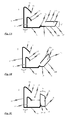
- a first preferred embodiment of a profile rail 1 for positioning a fastening element 21 in a groove formed between two spaced apart surface elements will be described in the production of a multiple glazing unit.
- the profiled rail 1 has a first leg section 10, a second leg section 20 and a bridge section 30, 31 for connecting the first leg section 10 to the second leg section 20. It is provided that the first leg portion 10 has two substantially mutually parallel side webs 11 each having a protruding from the associated side web 11 retaining web 12.
- the holding webs 12 are each designed as a resilient in the direction of the side web 11, sheet-shaped element.
- an abutment element 13 is provided in the form of a substantially perpendicular to the bridge section 30, 31 extending side surface. At this stop element 13 abuts the edge portion of a surface element, when the rail 1 is inserted over the edge portion of a surface element.
- the second leg section 20 is detachably connected to the bridge section 30, 31 and has a profile element 21 which is essentially U-shaped in cross-section and which forms the fastening element when the profile rail is used to produce a multiple glazing unit.
- the fastening element 21 determines a channel, which is open towards the outside with regard to the multiple glazing unit 100, and which is designed to accommodate a support element, not explicitly shown, of a support structure.
- the fastening element 21 has a shape of a U-shaped profile with two side bars 22a and 22b, which are interconnected with a connecting portion 23, which is preferably inclined at an angle of approximately 35 °. It can thus be achieved that in the finished multiple glazing unit 100, for example according to FIGS. 7A and 7B in that the filling material 106 can completely fill the space N between the spacer 105 and the surface elements 101, 102.
- This connection between the bridge portion 30, 31 and the second leg portion 20 serves to easily separate the second leg portion 20 from the bridge portion 30, 31 without damage to the second leg portion 20 when the second leg portion 20 is substantially separated U-shaped profile element 21 in the manufacture of a multiple glazing unit 100 in the groove N formed between two spaced-apart surface elements 101, 102 is held with a filler 106.
- the predetermined breaking point K between the second leg portion 20 and the bridge portion 30, 31 at the end of a step 31 of the bridge portion 30, 31 provided such that the second leg portion 20 with the cross-sectionally substantially U-shaped profile element 21 of a in Fig. 1A shown first position in an in Fig. 1C shown second position (and vice versa) is pivotable, wherein the pivot point in this pivotal movement at the junction K between the bridge portion 30, 31 and the second leg portion 20 is located.
- the second leg portion 20 is substantially perpendicular to the bridge portion 30, 31, whereas in the in Fig. 1A shown at least one side webs 22b of the cross-sectionally U-shaped profile of the fastener 21 is substantially in the plane of the bridge portion 30, 31.
- a latching mechanism 24, 32 is provided, which has a first locking member 24 at the free end of the side bar 22a and a complementary thereto formed second locking member 32 on the bridge section 30, 31.
- the two locking members 24, 32 are - as in Fig. 1B shown - in a preferably releasable (positive engagement) engageable, when the second leg portion 20 is substantially perpendicular to the bridge portion 30, 31.
- the bridge section 30, 31 has a first section 30 and a second section 31 which is step-shaped with respect to the plane in which the first section 30 lies.
- the step-shaped second portion 31 of the bridge portion 30, 31 forms a cover for the cross-sectionally substantially U-shaped profile element 21, so that between the side bars 22 a, 22 b and the Connecting portion 23 lying open channel of the substantially U-shaped profile element 21 is then covered accordingly.
- This cover formed with the second portion 31 of the bridge portion 30, 31 prevents filling material 106 from entering the space trapped between the side bars 22a, 22b and the connecting portion 23 when the rail 1 is used in manufacturing a multiple glazing unit 100.
- the second section 31 of the bridge section 30, 31 By forming the second section 31 of the bridge section 30, 31 in a step-shaped manner, it is possible to set the depth with which, in the production of a multiple glazing unit 100, the profile element 21 of the second leg section 20, which is essentially U-shaped in cross-section, in FIG is held between the two spaced-apart surface elements 101, 102 of the multiple glazing unit 100 groove formed when the rail 1 with at least one edge portion 101 ', 102' of the two surface elements 101, 102 is non-positively connected, so that the at least one edge portion 101 ', 102 'in a gap formed between the first and the second leg portion 10, 20 P is received and the second leg portion 20 is held in the groove N formed between the two spaced-apart surface elements 101, 102.
- the synopsis shows the FIGS. 1 and 5 to 7 in that in the profile rail 1 according to Fig. 1C the first and second leg sections 10, 20 are formed on the bridge section 30, 31 in such a way that the profile rail 1 can be frictionally connected to at least one edge section 101 ', 102' of the two surface elements 101, 102 forming the multiple glazing unit 100, so that the at least one an edge portion 101 ', 102' is received in the space P formed between the first and second leg portions 10, 20, and the second leg portion 20 is held in the groove N formed between the two spaced-apart surface members 101, 102.
- the holding of the second leg portion 20 in the groove N formed between the two spaced-apart surface elements 101, 102 is used in the manufacture of the multi-glazing unit 100 to position the cross-sectionally substantially U-shaped profile element 21 of the second leg portion 20 in the groove N and provisionally fix before the groove N is filled with the filler 106.
- the first and second leg sections 10, 20 of the profiled rail 1 are formed on the bridge section 30 of the profiled rail 1 in such a way that - as in particular in FIG FIGS. 5A and 5B shown in the manufacture of the multiple glazing unit 100, the rail 1 over at least one edge portion 101 ', 102' of the two surface elements 101, 102 can be plugged, wherein at least one edge portion 101 ', 102' of the two surface elements 101, 102 of the manufactured multiple glazing unit 100 in the between the first and second leg portions 10, 20 can be achieved that with the rail 1, the fastening element 21 in the formed between the respective edge portions 101 ', 102' of the two spaced-apart surface elements 101, 102 groove N are optimally positioned in a particularly easy and error-free manner can.
- At least one first leg portion 10 at least one substantially perpendicular to the bridge portion 30 extending side web 11 with at least one of the side web 11 in the direction of the second leg portion 20 projecting support web 12.
- This embodiment is particularly suitable when the distance L between the at least one side web 11 and the first leg portion 10 facing side of the cross-sectionally substantially U-shaped profile element 21 of the second leg portion 20 is greater than the thickness of the in between the first and second leg portion 10, 20 formed intermediate space P edge portion 101 ', 102' of the surface element 101, 102 is.
- FIGS. 5A and 5B With regard to the profiled rail 1, provision is made in this connection in particular for the at least one retaining web 12 projecting from the side web 11 to be designed such that, when the profiled rail 1 is inserted over the edge section 101 'of the surface element 101, to the first leg section 10 facing side of the surface element 101 abuts, the edge portion 101 'is received in the intermediate space P formed between the first and the second leg portion 10, 20.
- the profiled rail 1 such that at least one first leg section 10 has at least one substantially perpendicular to the bridge section 30 extending side web 11, wherein the distance L between the at least one side web 11 and the first leg portion 10 facing Side of the substantially U-shaped in cross-section profile element 21 of the second leg portion 20 is substantially identical to the thickness of the in between the first and second leg portion 10, 20 formed intermediate space P edge portion 101 ', 102' of the surface element 101, 102 is.
- the profile rail 1 is formed such that the distance L between the at least one side web 11 of the first leg portion 10 and the first leg portion 10 facing side of the cross-section substantially U-shaped formed profile element 21 of the second leg portion 20 is greater than the thickness of the in the formed between the first and second leg portion 10, 20 edge portion 101 ', 102' of the surface element 101, 102, it is preferred that at least one of the at least To perform a side web 11 of the first leg portion 10 projecting retaining web 12 as a resilient in the direction of the associated side web 11, preferably sheet-shaped element. It would be conceivable here, for example, that the at least one holding web 12 projecting from the at least one side web 11 of the first leg section 10 is formed from a flexible material and / or has a soft consistency compared to the material of the side web 11.
- each with different strong surface elements 101, 102 are used, since the distance L between the first and the second leg portion 10, 20 of the rail 1, and thus the size of the between the first and the second leg portion 10, 20 formed gap P, is flexible in a certain range and to the thickness of the male edge portion 101 ', 102' of the surface element 101, 102 adapts.
- FIGS. 5A to 7A as well as in FIGS. 5B to 7B are each different stages in the manufacture of a multiple glazing unit 100 using the in Fig. 1C shown profiled rail 1 shown.
- the profiled rail 1 with the at least one of the at least one side web 11 of the first leg portion 10 projecting holding web 12, which is designed as a resilient towards the associated side web 11, preferably sheet-shaped element, over different thickness edge portions 101 '. of the respective surface element 101 is pluggable, wherein in principle the respective edge portion 101 'in the intermediate space P formed between the first and the second leg portion 10, 20 is positively received.
- Fig. 2 to Fig. 4 described further preferred embodiments of the rail 1, which are suitable in the manufacture of a multiple glazing unit 100, in particular for positioning and provisionally fixing a fastener 21 in a groove N formed between two spaced-apart surface elements 101, 102.
- Fig. 2 is a cross-sectional view of a rail 1 according to a second preferred embodiment shown, which is identical in principle to the rail according to the first preferred embodiment, which, however, in comparison to the rail according to Fig. 1C an extended bridge portion 30, 31 has.
- the step-shaped second section 31 of the bridge section 30, 31 clearly over the opening of the formed with the side bars 22a, 22b and the connecting portion 23 channel of the substantially U-shaped profile element 21, so that the releasable connection (predetermined breaking point K) between the second leg portion 20 and the bridge portion 30, 31 from the free end of the second portion 31 of the bridge portion 30, 31 is present.
- profiled rail 1 thus comes to the bridge portion 30, 31 in addition to the covering function of the cross-sectionally substantially U-shaped profile element 21 in addition to the function of covering the entire overall groove N, if the rail 1 - as in Fig. 5A or Fig. 5B shown - plugged over the edge portion 101 'of the surface element 101, for example, and thus the edge portion 101' is positively received in the space P formed between the first and the second leg portion 10, 20.
- the bridge section 30, 31 is preferably at least as long in cross section as the distance between the surface elements 101, 102 of the multiple glazing unit 100 to be produced, which substantially simplifies the formation of the material ring 106 during the production of the multiple glazing unit 100. Namely, if the rail 1 is frictionally connected to at least one edge portion 101 ', 102' of the two surface elements 101, 102 and the at least one edge portion 101 ', 102' is received in the intermediate space P formed between the first and the second leg portion 10, 20, The bridging section 30, 31 covers the groove N formed between the two spaced-apart surface elements 101, 102, in which the profiled rail 1, which is essentially U-shaped in cross-section, is also held with the profiled rail 1. In the subsequent formation of the material ring 106 by filling a filling material into the groove N, the initially flowable filling material is held in the groove N by means of the groove N overlapping bridge portion 30, 31 until the filler has solidified sufficiently.
- Fig. 3 shows a profiled rail 1 in cross-sectional view according to a third preferred embodiment, which in the manufacture of a multi-glazing unit 100th is particularly adapted to provisionally fix a fastener 21 in a groove N formed between two spaced-apart surface elements 101, 102 at a position at which the fastener 21 is not immediately adjacent to one of the surface elements 101, 102.
- the third embodiment is a profile rail, which has a total of two first leg portions 10, 10 ', which are connected to the bridge portion 30, 31, that the second leg portion 20 between the two first leg portions 10, 10 'is arranged, and that in each case a gap P, P' between one of the first leg portions 10, 10 'and the second leg portion 20 is formed.
- the two first leg sections 10, 10 ' are formed on the bridge section 30, 31 in such a way that the profile rail 1 can be plugged over both edge sections 101', 102 'of the surface elements 101, 102 to be produced in the multiple glazing unit 100, so that in each case one the edge portions 101 ', 102' of the two surface elements 101, 102 are accommodated with the leg portions 10, 10 ', 20, and the second leg portion 20 is held in the groove N between the two spaced surface elements 101, 102 ,
- a fourth preferred embodiment of a rail 1 is shown in cross-sectional view, which substantially the in Fig. 3 shown in the third embodiment, and which in the manufacture of a multiple glazing unit 100 is particularly adapted to simultaneously fix a plurality of fasteners 21 in a formed between two spaced surface elements 101, 102 groove N at a respective position temporarily, in which the fastener 21 is not immediately adjacent to one of the surface elements 101, 102.
- profiled rails 1 are particularly suitable for use in the production of a multiple glazing unit 100 in which a fastening element 21 is arranged in a groove N formed between two spaced-apart surface elements 101, 102, this fastening element 21 being provided by the fixing element 21 Cross section is formed substantially U-shaped profile element 21 of the rail 1.
- Fig. 5 to Fig. 7 the method according to the invention for producing a multiple glazing unit 100 is described. In detail is in Fig. 5 to Fig. 7 shown as using the rail 1 according to Fig. 1C Multiple glazing units 100 each having different strong surface elements 101 can be produced.
- Fig. 5A or. Fig. 5B each shown in a cross-sectional view of an unfinished double glazing unit when clamping a rail 1 according to the first preferred embodiment for positioning and provisionally fixing the fastener 21 in the groove N formed between the two spaced-apart surface elements 101, 102.
- Fig. 6A or. Fig. 6B is in each case in a cross-sectional view in Fig. 5A or.
- Fig. 5B shown double glazing unit 100 after clamping the profile rail 1 and after forming a material ring 106 in the groove N formed between the two spaced-apart surface elements 101, 102, while in Fig. 7A or.
- Fig. 7B each in a cross-sectional view of the finished double glazing unit 100 according to Fig. 5A or. Fig. 5B is shown.
- a profile rail 1 and two preferably glass-like surface elements 101, 102 are provided. Subsequently, the two surface elements 101, 102 are arranged in an opposing and spaced-apart relationship, the distance between the surface elements 101, 102 being defined by a spacer 105 arranged between the surface elements 101, 102, and the two surface elements 101, 102 being arranged in this way be that on the one hand between the spaced surface elements 101, 102 and the spacer 105, a gas space G is included, and that on the other hand with the respective edge portions 101 ', 102' of the surface elements 101, 102 and the spacer 105 is an at least partially circumferentially extending groove N is formed.
- the profile rail 1 is then placed on the formed with the respective edge portions 101 ', 102' of the surface elements 101, 102 and the spacer 105 groove N such that at least one edge portion 101 ', 102' of the two surface elements 101, 102 in the between the first and the second leg portion 10, 20 of the rail 1 formed gap formed P and the second leg portion 20 of the rail 1 is held in the formed between the two spaced surface elements 101, 102 groove N.
- a material ring 106 is formed in the groove N. This is preferably done by a filling material is introduced into the groove N such that the second leg portion 20 of the rail 1 is at least partially enclosed by the filler material.
- a filling material is introduced into the groove N such that the second leg portion 20 of the rail 1 is at least partially enclosed by the filler material.
- Fig. 6A or. Fig. 6B the multiple glazing unit 100 is shown with an already formed material collar 106.
- FIGS. 7A and 7B In each case, in a cross-sectional view, the finished multiple glazing unit 100 is shown, which has the two spaced-apart surface elements 101, 102, wherein the first surface element 101 forms, for example, the inner pane of the glazing unit 100.
- the gas space G is delimited between the surface elements 101, 102 by the circumferentially extending spacer 105, which is formed of galvanized steel, for example, and between the spacer 105 and each of the disks 101, 102 is preferably a layer of a sealing material, such as polyisobutylene, can be laid.
- FIG Fig. 7A or. Fig. 7B the material ring 106 is provided, which fills the space N between the spacer 105 and the surface elements 101, 102, and which holds the two surface elements 101, 102 together.
- the fixing element 21 is immersed in the filling material 106.
- Fig. 7A or. Fig. 7B shown finished multiple glazing unit 100 are the free ends of the fastening element forming side bars 22a, 22b substantially flush with the edge of the two surface elements 101, 102 at;
- the invention is not limited to such a flush concern. Rather, it is possible by the use of the rail 1, the fastener 21, if necessary, to position deeper in the groove N or at other positions within the groove N.
- the fastening element 21 should have a width which is preferably less than half the distance between the spaced-apart surface elements 101, 102. This can ensure that when forming the material ring 106, the filling material with a sufficiently large surface of the respective surface elements 101, 102 come into contact so as to provide a reliable bond.
- the invention is not limited to the preferred embodiment of the rail 1 shown in the drawings. Rather, any combination of the individual features specified in the claims with respect to the rail 1 are conceivable.
- the inventive method for producing a multiple glazing unit 100 is not limited to the use of the in Fig. 1C limited shown rail.
- the profile rail is preferably made of a plastic, in particular polyethylene, polypropylene or polyethylene terephthalate.
- a plastic in particular polyethylene, polypropylene or polyethylene terephthalate.
- polyethylene polyethylene
- polypropylene polypropylene
- polyethylene terephthalate polyethylene terephthalate
Abstract
Description
Die vorliegende Erfindung betrifft eine Profilschiene zum Positionieren eines Befestigungselements in einer zwischen zwei voneinander beabstandeten Flächenelementen gebildeten Nut bei der Herstellung einer Mehrfachverglasungseinheit und ein Verfahren zum Herstellen einer Mehrfachverglasungseinheit.The present invention relates to a rail for positioning a fastener in a groove formed between two spaced-apart sheet members in the manufacture of a multiple glazing unit and a method of manufacturing a multiple glazing unit.
Aus der Druckschrift
Zur Herstellung einer derartigen Mehrfachverglasungseinheit wird in der Druckschrift
Im Hinblick auf das provisorische Fixieren des Befestigungselements an dem einen Randabschnitt der beiden Flächenelemente ist beim Stand der Technik vorgesehen, unter Verwendung eines Klebstoffes oder eines doppelseitigen Klebebandes das Befestigungselement mit einem seiner Schenkelabschnitte auf den betreffenden Randabschnitt aufzukleben. Bei der Herstellung der Mehrfachverglasungseinheit sollte dies vorzugsweise erfolgen, bevor die beiden Flächenelemente in der gegenüberliegenden und voneinander beabstandeten Beziehung relativ zueinander angeordnet werden.With regard to the provisional fixing of the fastening element on the one edge portion of the two surface elements is provided in the prior art, using an adhesive or a double-sided adhesive tape to attach the fastener with one of its leg portions on the respective edge portion. In the manufacture of the multiple glazing unit, this should preferably be done before the two surface elements are arranged in the opposite and spaced relationship relative to each other.
Da vor dem Anordnen der beiden Flächenelemente das Befestigungselement bereits auf dem Randabschnitt eines der beiden Flächenelementes aufgeklebt wurde, liegt nach dem Anordnen der beiden Flächenelemente dieses Befestigungselement unmittelbar angrenzend an dem Randabschnitt des einen Flächenelements und innerhalb der mit den jeweiligen Randabschnitten der Flächenelemente und dem Abstandshalter gebildeten Nut.Since, prior to the arrangement of the two surface elements, the fastening element has already been adhesively bonded to the edge section of one of the two surface elements, after the two surface elements have been arranged, this fastening element lies directly adjacent to the edge section of the one surface element and within the one with the respective edge sections of the surface elements and the spacer groove.
Mit dem bekannten Verfahren ist es somit möglich, eine für eine Strukturverglasungstechnik geeignet einbaufertige Mehrfachverglasungseinheit herzustellen. Diese Strukturverglasungstechnik ermöglicht es, beispielsweise Fassaden derart mit einer Strukturverglasung zu verkleiden, ohne dass nach außen hin sichtbare Trägerprofile verbleiben.With the known method, it is thus possible to produce a multi-glazing unit which is suitable for structural glazing technique and ready for installation. This structural glazing technique makes it possible, for example, to cover facades with structural glazing without leaving visible support profiles to the outside.
Das aus dem Stand der Technik bekannte Verfahren zum Herstellen einer derartigen Mehrfachverglasungseinheit weist allerdings den Nachteil auf, dass bei der provisorischen Fixierung des Befestigungselements an dem Randabschnitt des einen Flächenelements eine genaue Positionierung des Befestigungselements in der mit den jeweiligen Randabschnitten der Flächenelemente und dem Abstandshalter gebildeten Nut relativ zeit- und arbeitsintensiv ist. Um kontinuierlich eine hohe Qualität der fertiggestellten Mehrfachverglasungseinheiten zu ermöglichen, ist es allerdings insbesondere erforderlich, dass bei der provisorischen Fixierung des Befestigungselements an dem Randabschnitt des einen Flächenelements die freien Enden der Schenkelabschnitte des Befestigungselements möglichst bündig mit den jeweiligen Kanten der beiden Flächenelemente abschließen, und vor allem nicht über das Niveau der jeweiligen Kanten der Flächenelemente hinausstehen. Ansonsten besteht die Gefahr, dass bei der fertiggestellten Mehrfachverglasungseinheit das Befestigungselement nicht in optimaler Weise das Trägerelement der Trägerstruktur aufnehmen kann.However, the method known from the prior art for producing such a multiple glazing unit has the disadvantage that in the provisional fixation of the fastener to the edge portion of a surface element a precise positioning of the fastener in the groove formed with the respective edge portions of the surface elements and the spacer relatively time and is labor intensive. In order to continuously enable a high quality of the finished multiple glazing units, however, it is particularly necessary that when provisionally fixing the fastener to the edge portion of a surface element, the free ends of the leg portions of the fastener as flush as possible flush with the respective edges of the two surface elements, and before In particular, do not exceed the level of the respective edges of the surface elements. Otherwise, there is a risk that in the finished multiple glazing unit, the fastener can not absorb the carrier element of the support structure in an optimal manner.
Um die erforderliche Positioniergenauigkeit des Befestigungselements in der zwischen den beiden beabstandeten Flächenelementen gebildeten Nut zu erreichen, ist es bei dem aus dem Stand der Technik bekannten Verfahren zum Herstellen einer Mehrfachverglasungseinheit erforderlich, in kontrollierter Weise zunächst das Klebeband oder den Klebstoff auf den Randabschnitt des Flächenelements bzw. auf den Schenkelabschnitt des in Gestalt eines im Querschnitt U-förmigen Profils ausgebildeten Befestigungselement aufzubringen. Anschließend muss das Befestigungselement möglichst genau am Randabschnitt des Flächenelements positioniert und angedrückt werden. Diese sowohl für das Positionieren des Befestigungselements in der zwischen den beiden beabstandeten Flächenelementen gebildeten Nut, als auch für das provisorische Fixieren des Befestigungselements an dem Randabschnitt des einen Flächenelements erforderlichen Arbeitsschritte sollten von Fachkräften durchgeführt und kontrolliert werden, infolgedessen der Herstellungsprozess der Mehrfachverglasungseinheit nicht nur verhältnismäßig zeit- sondern auch arbeitsintensiv ist.In order to achieve the required positioning accuracy of the fastening element in the groove formed between the two spaced surface elements, it is necessary in the known from the prior art method for producing a multiple glazing unit, in a controlled manner first the tape or the adhesive to the edge portion of the surface element or on the leg portion of the formed in the form of a cross-sectionally U-shaped profile fastener. Subsequently, the fastener must be positioned and pressed as accurately as possible on the edge portion of the surface element. These steps required both for positioning the fastener in the groove formed between the two spaced surface elements and for provisionally fixing the fastener to the edge portion of the surface element should be performed and controlled by skilled workers, as a result of which the manufacturing process of the multiple glazing unit is not only relatively time consuming - but also labor intensive.
Andererseits ist es bei dem aus dem Stand der Technik bekannten Verfahren nicht oder nur mit großem Aufwand möglich, das Befestigungselement nachträglich in der zwischen den beiden beabstandeten Flächenelementen und dem Abstandshalter ausgebildeten Nut zu positionieren, d.h. nachdem die beiden Flächenelemente in ihrer gegenüberliegenden und voneinander beabstandeten Beziehung angeordnet wurden. Auch ist es nicht möglich, das Befestigungselement in der Nut derart provisorisch zu fixieren, dass das Befestigungselement nicht unmittelbar an einem Randabschnitt eines der beiden Flächenelemente angrenzt.On the other hand, it is in the known from the prior art method, or only with great effort possible to position the fastener subsequently in the formed between the two spaced surface elements and the spacer groove, i. after the two surface elements have been arranged in their opposite and spaced relationship. Also, it is not possible to provisionally fix the fastening element in the groove such that the fastening element does not directly adjoin an edge section of one of the two surface elements.
Von daher ist das aus dem Stand der Technik bekannte Verfahren nicht zum Herstellen von Mehrfachverglasungseinheiten geeignet, bei denen das Befestigungselement beispielsweise mittig zwischen den beiden beabstandeten Flächenelementen anzuordnen ist.Therefore, the method known from the prior art is not suitable for producing multiple glazing units in which the fastening element is to be arranged, for example, centrally between the two spaced-apart area elements.
Auf der Grundlage der zuvor geschilderten Problemstellung liegt somit der vorliegenden Erfindung die primäre Aufgabe zugrunde, ein Verfahren zum Herstellen einer Mehrfachverglasungseinheit anzugeben, bei welchem vor oder nach dem zum Ausbilden eines Materialkranzes erfolgten Einbringen eines Füllmaterials, insbesondere eines Harz- oder Silikonmaterials, in der zwischen den beiden Flächenelementen ausgebildeten Nut das Befestigungselements in der zwischen den beiden Flächenelementen ausgebildeten Nut wesentlich einfacher positioniert und provisorisch fixiert werden kann, ohne dass die erforderliche Positioniergenauigkeit des Befestigungselements in der Nut verschlechtert wird. Insbesondere soll ein leicht zu realisierendes Verfahren zum Herstellen einer Mehrfachverglasungseinheit angegeben werden, bei welchem mit einer reduzierten Anzahl von Arbeitsschritten Mehrfachverglasungseinheiten mit durchgehend guter Qualität herstellbar sind.On the basis of the problem described above, the present invention is therefore based on the primary object of specifying a method for producing a multiple glazing unit, in which before or after the introduction of a filling material, in particular a resin or silicone material, takes place in order to form a material ring formed the two surface elements groove, the fastener in the groove formed between the two surface elements much easier positioned and can be provisionally fixed without the required positioning accuracy of the fastener is deteriorated in the groove. In particular, an easy-to-implement method for producing a multiple glazing unit is to be specified, in which multiple glazing units of consistently good quality can be produced with a reduced number of work steps.
Diese Aufgabe wird erfindungsgemäß dadurch gelöst, dass bei der Herstellung der Mehrfachverglasungseinheit eine Profilschiene mit zumindest einem ersten Schenkelabschnitt, einem zweiten Schenkelabschnitt und einem den ersten und zweiten Schenkelabschnitt verbindenden Brückenabschnitt zum Einsatz kommt, wobei der zweite Schenkelabschnitt der Profilschiene lösbar mit dem Brückenabschnitt verbunden ist und ein im Querschnitt im wesentlichen U-förmiges Profilelement aufweist, und wobei das in der zwischen den beiden Randabschnitten der Flächenelemente ausgebildeten Nut zu positionierende Befestigungselement durch das im Querschnitt im wesentlichen U-förmiges Profilelement der Profilschiene ausgebildet wird.This object is achieved in that in the manufacture of the multiple glazing unit a profile rail with at least a first leg portion, a second leg portion and a connecting the first and second leg portion bridge portion is used, wherein the second leg portion of the rail is releasably connected to the bridge portion and a profile element which is essentially U-shaped in cross-section and in which the fastening element to be positioned in the groove formed between the two edge sections of the surface elements is formed by the profile element of the profile rail which is substantially U-shaped in cross-section.
Im Hinblick auf die bei der Herstellung der Mehrfachverglasungseinheit zum Einsatz kommenden Profilschiene ist dabei vorgesehen, dass die ersten und zweiten Schenkelabschnitte derart auf dem Brückenabschnitt ausgebildet sind, dass die Profilschiene mit zumindest einem Randabschnitt der beiden Flächenelemente kraftschlüssig verbindbar ist, so dass der zumindest eine Randabschnitt in einem zwischen dem ersten und dem zweiten Schenkelabschnitt gebildeten Zwischenraum aufgenommen und der zweite Schenkelabschnitt in der zwischen den beiden voneinander beabstandeten Flächenelementen gebildeten Nut gehalten wird.With regard to the profile rail used in the production of the multiple glazing unit, it is provided that the first and second leg sections are formed on the bridge section in such a way that the profile rail can be frictionally connected to at least one edge section of the two surface elements, so that the at least one edge section received in a space formed between the first and second leg portion and the second leg portion is held in the groove formed between the two spaced-apart surface elements.
Die mit der Verwendung der Profilschiene bei der Herstellung einer Mehrfachverglasungseinheit erzielbaren Vorteile liegen insbesondere darin, dass mit der Profilschiene das Befestigungselement in der zwischen den jeweiligen Randabschnitten der beiden voneinander beabstandeten Flächenelementen gebildeten Nut in besonders leichter und fehlerfreien Weise optimal positioniert werden kann. Dadurch, dass die Profilschiene mit zumindest einem der beiden Randabschnitte der Flächenelemente kraftschlüssig verbindbar ist, kann auf eine Verklebung des Befestigungselements am Randabschnitt eines der beiden Flächenelemente vollständig verzichtet werden. Vielmehr kommt bei der vorgeschlagenen Lösung eine Profilschiene zum Einsatz, die beispielsweise wie eine Klemme über den Randabschnitt eines der beiden Flächenelemente aufgesteckt wird. Dabei ist diese Klemme derart ausgebildet, dass die Profilschiene kraftschlüssig mit zumindest einem Randabschnitt der beiden Flächenelemente in einem kraftschlüssigen Eingriff steht und das im Querschnitt im wesentlichen U-förmige Profilelement des zweiten Schenkelabschnittes in einer vorgebbaren Position innerhalb der Nut zwischen den beiden beabstandeten Flächenelementen hält.The advantages that can be achieved with the use of the profile rail in the production of a multiple glazing unit are, in particular, that with the profile rail, the fastening element in the groove formed between the respective edge sections of the two spaced-apart surface elements is particularly light and error-free Way can be optimally positioned. Due to the fact that the profile rail can be frictionally connected to at least one of the two edge sections of the surface elements, adhesive bonding of the fastening element to the edge section of one of the two surface elements can be completely dispensed with. Rather, in the proposed solution, a profile rail is used, which is attached, for example, like a clamp on the edge portion of one of the two surface elements. In this case, this terminal is designed such that the rail is frictionally engaged with at least one edge portion of the two surface elements in a frictional engagement and holds the cross-sectionally substantially U-shaped profile element of the second leg portion in a predetermined position within the groove between the two spaced surface elements.
Im Hinblick auf das Verfahren zum Herstellen einer Mehrfachverglasungseinheit ist im einzelnen vorgesehen, dass zunächst die Profilschiene mit dem zumindest einen ersten Schenkelabschnitt, dem zweiten Schenkelabschnitt und dem den ersten und zweiten Schenkelabschnitt verbindenden Brückenabschnitt und zwei vorzugsweise glasartige Flächenelemente bereitgestellt werden. Anschließend werden die beiden Flächenelemente in einer gegenüberliegenden und voneinander beabstandeten Beziehung angeordnet, wobei der Abstand zwischen den Flächenelementen mit einem zwischen den Flächenelementen angeordneten Abstandshalter definiert wird, und wobei die beiden Flächenelemente derart angeordnet werden, dass einerseits zwischen den beabstandeten Flächenelementen und dem Abstandshalter ein Gasraum eingeschlossen wird, und dass andererseits mit den jeweiligen Randabschnitten der Flächenelemente und dem Abstandshalter eine sich zumindest teilweise umfangsmäßig erstreckende Nut gebildet wird. Danach wird in der Nut ein Materialkranz ausgebildet, und zwar indem ein Füllmaterial, insbesondere ein Harz- oder Silikonmaterial, in die Nut eingebracht wird.With regard to the method for producing a multiple glazing unit, it is provided in detail that the profile rail is first provided with the at least one first leg section, the second leg section and the bridge section connecting the first and second leg sections and two preferably glass-like planar elements. Subsequently, the two surface elements are arranged in an opposing and spaced-apart relationship, wherein the distance between the surface elements is defined by a spacer arranged between the surface elements, and wherein the two surface elements are arranged such that on the one hand between the spaced surface elements and the spacer, a gas space is included, and on the other hand with the respective edge portions of the surface elements and the spacer an at least partially circumferentially extending groove is formed. Thereafter, a material ring is formed in the groove, by a filler material, in particular a resin or silicone material, is introduced into the groove.
Erfindungsgemäß ist bei dem Verfahren vorgesehen, dass entweder vor oder nach dem Verfahrensschritt des Ausbildens des Materialkranzes in der Nut die Profilschiene auf die mit den jeweiligen Randabschnitten der Flächenelemente und dem Abstandshalter gebildete Nut derart aufgesteckt wird, dass zumindest ein Randabschnitt der beiden Flächenelemente in einem zwischen dem ersten und dem zweiten Schenkelabschnitt der Profilschiene gebildeten Zwischenraum aufgenommen und der zweite Schenkelabschnitt der Profilschiene in der zwischen den beiden beabstandeten Flächenelementen gebildeten Nut gehalten wird. Schließlich wird die Verbindung zwischen dem zweiten Schenkelabschnitt und dem Brückabschnitt der Profilschiene getrennt, um die Mehrfachverglasungseinheit mit dem im Materialkranz gehaltenen Befestigungselement zu erhalten.According to the invention, it is provided in the method that either before or after the step of forming the material ring in the groove, the rail is placed on the formed with the respective edge portions of the surface elements and the spacer groove such that at least one edge portion of the two surface elements in an intermediate the first and second leg portion of the rail formed intermediate space and the second leg portion of the rail is held in the groove formed between the two spaced surface elements. Finally, the connection between the second leg portion and the bridge portion of the rail is separated to obtain the multiple glazing unit with the fastener held in the material collar.
Wenn bei dem erfindungsgemäßen Verfahren der Verfahrensschritt des Aufsteckens der Profilschiene auf die Nut vor dem Verfahrensschritt des Ausbildens des Materialkranzes in der Nut erfolgt, ist es bevorzugt, dass beim Verfahrensschritt des Ausbildens des Materialkranzes in der Nut das Füllmaterial derart in die Nut eingebracht wird, dass der zweite Schenkelabschnitt der Profilschiene von dem Füllmaterial zumindest teilweise umschlossen wird.If, in the method according to the invention, the method step of plugging the profile rail onto the groove takes place before the method step of forming the material ring in the groove, it is preferred that in the method step of forming the material ring in the groove, the filling material is introduced into the groove such that the second leg portion of the rail is at least partially enclosed by the filler material.
Wenn andererseits bei dem erfindungsgemäßen Verfahren der Verfahrensschritt des Aufsteckens der Profilschiene auf die Nut nach dem Verfahrensschritt des Ausbildens des Materialkranzes in der Nut erfolgt, ist es bevorzugt, dass die Profilschiene derart auf die Nut aufgesteckt wird, dass der zweite Schenkelabschnitt der Profilschiene von dem in die Nut eingebrachten Füllmaterial zumindest teilweise umschlossen wird.If, on the other hand, in the method according to the invention the step of attaching the profiled rail to the groove takes place after the step of forming the material ring in the groove, it is preferred that the profiled rail is fitted onto the groove in such a way that the second leg section of the profiled rail differs from that in FIG the groove introduced filling material is at least partially enclosed.
In einer bevorzugten Realisierung des erfindungsgemäßen Verfahrens wird zum Ausbilden eines Materialkranzes in der Nut als Füllmaterial ein vorzugsweise bei Raumtemperatur aushärtbares Harzmaterial oder ein vorzugsweise bei Raumtemperatur polymerisierbares Silikonmaterial verwendet. Bei dem Silikonmaterial sollte es sich in vorteilhafter Weise um ein Material handeln, welches im polymerisierten Zustand zumindest teilweise dauerelastisch ist. Selbstverständlich kommen hier aber auch andere Materialien in Frage.In a preferred realization of the method according to the invention, a preferably room temperature curable resin material or a preferably room temperature polymerizable silicone material is used to form a ring of material in the groove as filler material. The silicone material should advantageously be a material which is at least partially permanently elastic in the polymerized state. Of course, other materials come into question here.
Vorteilhafte Weiterbildungen der bei der Herstellung einer Mehrfachverglasungseinheit zum Einsatz kommenden Profilschiene zum Positionieren und provisorischen Fixieren eines Befestigungselementes in der zwischen den beiden Randabschnitten der Flächenelemente gebildeten Nut sind in den Unteransprüchen angegeben.Advantageous developments of the profile rail used in the manufacture of a multiple glazing unit for positioning and provisionally fixing a fastening element in the groove formed between the two edge sections of the surface elements are specified in the subclaims.
So ist in einer besonders bevorzugten Realisierung vorgesehen, dass die ersten und zweiten Schenkelabschnitte der Profilschiene derart auf dem Brückenabschnitt der Profilschiene ausgebildet sind, dass die Profilschiene über zumindest einen der beiden Randabschnitte der Flächenelemente steckbar ist. Insbesondere ist es hierbei denkbar, dass die ersten und zweiten Schenkelabschnitte derart auf dem Brückenabschnitt ausgebildet sind, dass die Profilschiene über zumindest einen Randabschnitt der beiden Flächenelemente steckbar ist, so dass der zumindest eine Randabschnitt in dem zwischen dem ersten und dem zweiten Schenkelabschnitt gebildeten Zwischenraum formschlüssig aufgenommen und die Profilschiene in der Nut zwischen den beiden beabstandeten Flächenelementen der Mehrfachverglasungseinheit kraft- und formschlüssig gehalten wird.Thus, it is provided in a particularly preferred realization that the first and second leg portions of the rail are formed on the bridge portion of the rail so that the rail is plugged over at least one of the two edge portions of the surface elements. In particular, it is conceivable that the first and second leg portions are formed on the bridge portion such that the profile rail can be plugged over at least one edge portion of the two surface elements, so that the at least one edge portion in the intermediate space formed between the first and the second leg portion form fit taken and the rail in the groove between the two spaced surface elements of the multiple glazing unit is positively and positively held.
Dieses kraft- und formschlüssige Halten des zweiten Schenkelabschnittes der Profilschiene in der Nut zwischen den beiden beabstandeten Flächenelementen der Mehrfachverglasungseinheit wird vorzugsweise dadurch erreicht, dass zumindest einer der ersten Schenkelabschnitt zumindest einen im wesentlichen senkrecht zum Brückenabschnitt verlaufenden Seitensteg aufweist, wobei der Abstand zwischen dem Seitensteg des ersten Schenkelabschnittes und der dem ersten Schenkelabschnitt zugewandten Seite des im Querschnitt im wesentlichen U-förmigen Profilelementes des zweiten Schenkelabschnitts im wesentlichen identisch mit der Dicke desjenigen Randabschnittes des Flächenelementes ist, der in dem zwischen dem ersten und zweiten Schenkelabschnitt gebildeten Zwischenraum aufgenommen wird, wenn die Profilschiene über den Randabschnitt des Flächenelements gesteckt ist.This non-positive and positive holding the second leg portion of the rail in the groove between the two spaced surface elements of the multiple glazing unit is preferably achieved in that at least one of the first leg portion has at least one substantially perpendicular to the bridge portion extending side web, wherein the distance between the side web of the first leg portion and the first leg portion side facing the cross-sectionally substantially U-shaped profile element of the second leg portion is substantially identical to the thickness of that edge portion of the surface element which is received in the intermediate space formed between the first and second leg portion, when the rail is inserted over the edge portion of the surface element.
Alternativ oder zusätzlich hierzu ist es allerdings auch denkbar, dass wenigstens ein erster Schenkelabschnitt zumindest einen im wesentlichen senkrecht zum Brückenabschnitt verlaufenden Seitensteg mit zumindest einen vom Seitensteg in Richtung zum zweiten Schenkelabschnitt abstehenden Haltesteg aufweist, wobei der Abstand zwischen dem zumindest einen Seitensteg des ersten Schenkelabschnittes und der dem ersten Schenkelabschnitt zugewandten Seite des im Querschnitt im wesentlichen U-förmig ausgebildeten Profilelements des zweiten Schenkelabschnittes größer als die Dicke desjenigen Randabschnittes des Flächenelements ist, der in dem zwischen dem ersten und zweiten Schenkelabschnitt gebildeten Zwischenraum aufgenommen wird, wenn die Profilschiene über den Randabschnitt des Flächenabschnittes gesteckt ist, wobei der zumindest eine vom Seitensteg abstehende Haltesteg derart ausgebildet ist, dass er, wenn die Profilschiene über den Randabschnitt des Flächenelements gesteckt ist, an die dem ersten Schenkelabschnitt zugewandte Seite desjenigen Flächenelements anstößt, dessen Randabschnitt in dem zwischen dem ersten und dem zweiten Schenkelabschnitt gebildeten Zwischenraum aufgenommen ist.Alternatively or additionally, however, it is also conceivable that at least one first leg section has at least one side web extending substantially perpendicular to the bridge section with at least one holding web projecting from the side web towards the second leg section, wherein the distance between the at least one side web of the first leg section and the side facing the first leg portion of the profile element of the second leg portion formed in a substantially U-shaped section is greater than the thickness of that edge portion of the surface element which is received in the space formed between the first and second leg portion, when the rail over the edge portion of Surface portion is inserted, wherein the at least one of the side web projecting retaining web is formed such that it, when the rail is inserted over the edge portion of the surface element, a n the side facing the first leg portion that surface element abuts, the edge portion is received in the intermediate space formed between the first and the second leg portion.
In einer besonders bevorzugten Realisierung des zumindest einen vom Seitensteg des ersten Schenkelabschnittes abstehenden Haltesteges ist vorgesehen, dass dieser Haltesteg als ein in Richtung zum zugehörigen Seitensteg nachgiebiges, vorzugsweise blattförmiges Element ausgeführt ist. Denkbar allerdings wäre auch alternativ oder zusätzlich hierzu, dass der zumindest eine von dem zumindest einen Seitensteg des ersten Schenkelabschnittes abstehende Haltesteg aus einem flexiblen Material gebildet ist und eine im Vergleich zum Material des Seitenstegs weiche Konsistenz aufweist.In a particularly preferred realization of the at least one holding web projecting from the side web of the first leg section, it is provided that this holding web is designed as a resilient, preferably sheet-shaped element, in the direction of the associated side web. However, it would also be conceivable as an alternative or in addition to this that the at least one holding web projecting from the at least one side web of the first leg section is formed of a flexible material and has a soft consistency compared to the material of the side web.
Um zu erreichen, dass das Befestigungselement nicht nur unmittelbar angrenzend an dem Randabschnitt eines der beiden Flächenelemente positionierbar ist, ist in einer bevorzugten Weiterentwicklung der bei der Herstellung der Mehrfachverglasungseinheit zum Einsatz kommenden Profilschiene vorgesehen, dass die Profilschiene insgesamt zwei erste Schenkelabschnitte aufweist, die derart mit dem Brückenabschnitt verbunden sind, dass der zweite Schenkelabschnitt zwischen den beiden ersten Schenkelabschnitten angeordnet ist, und dass jeweils zwischen einem der ersten Schenkelabschnitte und dem zweiten Schenkelabschnitt ein Zwischenraum gebildet wird, wobei die beiden ersten Schenkelabschnitte derart ausgebildet sind, dass die Profilschiene über beide Randabschnitte der Flächenelemente steckbar ist, so dass die jeweiligen Randabschnitte der beiden Flächenelemente in jeweils einem der mit den Schenkelabschnitten gebildeten Zwischenräume aufgenommen werden und der zweite Schenkelabschnitt in der Nut zwischen den beiden beabstandeten Flächenelementen gehalten wird.In order to ensure that the fastening element can not only be positioned directly adjacent to the edge section of one of the two planar elements, in a preferred development of the profile rail used in the manufacture of the multiple glazing unit, it is provided that the profile rail comprises a total of two first leg sections which are in such a way the bridge portion are connected, that the second leg portion between the two first leg portions is arranged, and that in each case between one of the first leg portions and the second leg portion, a gap is formed, wherein the two first leg portions are formed such that the rail over both edge portions of Plane elements can be plugged, so that the respective edge portions of the two surface elements are accommodated in each one of the spaces formed with the leg portions and the second leg portion in the groove is held between the two spaced surface elements.
In einer bevorzugten Realisierung der Profilschiene ist schließlich vorgesehen, dass der zweite Schenkelabschnitt über eine Sollbruchstelle mit dem Brückenabschnitt verbunden ist, womit erreicht werden kann, dass nach dem Ausbilden des Materialkranzes in der zwischen den beiden beabstandet voneinander angeordneten Flächenelementen ausgebildeten Nut, und vorzugsweise nach dem (zumindest teilweisen) Aushärten oder Polymerisieren des zum Ausbilden des Materialkranzes verwendeten Füllmaterials, der zweite Schenkelabschnitt von der Profilschiene bzw. von dem Brückenabschnitt abgetrennt werden kann.In a preferred realization of the profile rail, it is finally provided that the second leg section is connected to the bridge section via a predetermined breaking point, whereby it can be achieved that, after the formation of the material ring, in the groove formed between the two spaced-apart surface elements, and preferably after (at least partially) curing or polymerizing the filling material used to form the material ring, the second leg portion can be separated from the rail or from the bridge portion.
Des weiteren ist bevorzugt vorgesehen, dass der Brückenabschnitt der Profilschiene im Querschnitt zumindest gleich lang wie der Abstand zwischen den Flächenelementen ist. Diese Maßnahme erleichtert das Einbringen des Füllmaterials in die Nut, um den Materialkranz auszubilden.Furthermore, it is preferably provided that the bridge section of the profile rail is at least as long in cross section as the distance between the surface elements. This measure facilitates the introduction of the filling material into the groove in order to form the material ring.
Im Hinblick auf das im Querschnitt im wesentlichen U-förmige Profilelement des zweiten Schenkelabschnittes ist vorzugsweise vorgesehen, dass dieses Profilelement zwei im wesentlichen senkrecht zum Brückenabschnitt verlaufende Seitenstege aufweist, die mit einem Verbindungsabschnitt miteinander verbunden sind, wobei der Verbindungsabschnitt vorzugsweise in solch einer Weise geneigt ist, dass der Seitensteg, welcher benachbart zu dem Flächenelement ist, welches in dem Zwischenraum zwischen dem ersten und dem zweiten Schenkelabschnitt der Profilschiene aufgenommen ist, länger als der andere Seitensteg ist. Der Neigungswinkel kann mehr als 10°, beispielsweise zwischen 10° und 45°, vorzugsweise zwischen 25° und 40°, und am bevorzugsten 35° betragen.With regard to the cross-sectionally substantially U-shaped profile element of the second leg portion is preferably provided that this profile element has two substantially perpendicular to the bridge portion extending side webs, which are connected to a connecting portion with each other, wherein the connecting portion is preferably inclined in such a manner in that the side land, which is adjacent to the surface element received in the space between the first and second leg portions of the rail, is longer than the other side land. The angle of inclination may be more than 10 °, for example between 10 ° and 45 °, preferably between 25 ° and 40 °, and most preferably 35 °.
Vorzugsweise ist das im Querschnitt im wesentlichen U-förmig ausgebildete Profilelement des zweiten Schenkelabschnittes ferner derart ausgeführt, dass es eine Breite aufweist, die geringer als der halbe Abstand zwischen dem ersten und dem zweiten Flächenelement ist, wodurch ausreichend Raum zwischen dem Befestigungselement und dem jeweiligen Flächenelement zum Einleiten des Füllmaterials geschaffen wird.Preferably, the cross-sectionally substantially U-shaped profile element of the second leg portion is further designed such that it has a width which is less than half the distance between the first and the second surface element, whereby sufficient space between the fastening element and the respective surface element is created for introducing the filler.
Weiterhin sollte das Befestigungselement vorzugsweise eine Tiefe aufweisen, die in etwa zwischen 25 % und 75 % der Tiefe des vom Füllmaterials zu belegenden bzw. belegten Raumes liegt. Dabei entspricht die Tiefe des vom Füllmaterials zu belegenden bzw. belegten Raumes dem Abstand des Abstandshalters von den jeweiligen Kanten der Flächenelemente. Dies gewährleistet, dass das Füllmaterial mit einer ausreichenden Fläche der jeweiligen Flächenelemente in Verbindung steht, um eine zuverlässige kraftschlüssige Verbindung damit zu schaffen, während gleichzeitig das im wesentlichen U-förmig ausgebildete Profilelement eine ausreichende Tiefe aufweist, um während der Verwendung eine sichere Befestigung der fertiggestellten Mehrfachverglasungseinheit zu gewährleisten.Furthermore, the fastening element should preferably have a depth which is approximately between 25% and 75% of the depth of the space to be occupied by the filling material. In this case, the depth of the space to be occupied or occupied by the filling material corresponds to the distance of the spacer from the respective edges of the surface elements. This ensures that the filler material communicates with a sufficient area of the respective surface elements to provide a reliable frictional connection therewith, while at the same time the substantially U-shaped profile element has sufficient depth to provide secure attachment of the finished during use To ensure multiple glazing unit.
Darüber hinaus ist es denkbar, eine Vielzahl von U-förmigen Profilelementen vorzusehen, welche sich gemeinsam um die Mehrfachverglasungseinheit herum erstrecken. Vorzugsweise ist eine Anzahl von Befestigungselementen vorgesehen, die sich gemeinsam im wesentlichen vollständig um den Umfang der Mehrfachverglasungseinheit herum erstrecken. Dies hat den Vorteil, dass die beste Befestigung der Mehrfachverglasungseinheit an der Trägerstruktur geschaffen wird. Wenn die Mehrfachverglasungseinheit beispielsweise eine im Allgemeinen rechtwinklige Gestalt besitzt, werden vorzugsweise vier Befestigungselemente vorgesehen, von denen sich jedes entlang einer entsprechenden Kante der Mehrfachverglasungseinheit erstreckt, wobei die Befestigungselemente zueinander im rechten Winkel angeordnet sind. Alternativ hierzu können Befestigungselemente nur an zwei, beispielsweise voneinander abgewandten Kanten der Mehrfachverglasungseinheit vorgesehen sein.Moreover, it is conceivable to provide a plurality of U-shaped profile elements which extend together around the multiple glazing unit. Preferably, a number of fasteners are provided which together extend substantially completely around the perimeter of the multiple glazing unit. This has the advantage of providing the best attachment of the multiple glazing unit to the support structure. For example, if the multi-glazing unit has a generally rectangular shape, four fasteners are preferably provided, each extending along a respective edge of the multi-glazing unit with the fasteners at right angles to one another. Alternatively, fasteners may be provided only on two, for example, facing away from each other edges of the multiple glazing unit.
Die Profilschiene ist vorzugsweise aus einem Kunststoffmaterial, insbesondere einem PVC-Material einstückig gebildet.The profile rail is preferably formed of a plastic material, in particular a PVC material in one piece.
Um die größte Festigkeit der Anordnung aus Abstandshalter, Flächenelementen und Befestigungselementen zu schaffen, erstreckt sich der Materialkranz vorzugsweise zumindest zwischen dem Abstandshalter und jedem der Flächenelemente.In order to provide the greatest strength of the arrangement of spacers, surface elements and fastening elements, the material ring preferably extends at least between the spacer and each of the surface elements.
Vorzugsweise ist das Füllmaterial ein vorzugsweise bei Raumtemperatur aushärtbares Harzmaterial oder ein vorzugsweise bei Raumtemperatur polymerisierbares Silikonmaterial. Bei dem Silikonmaterial sollte es sich in vorteilhafter Weise um ein Material handeln, welches im polymerisierten Zustand zumindest teilweise dauerelastisch ist. Selbstverständlich kommen hier aber auch andere Materialien in Frage.Preferably, the filler is preferably a room temperature curable resin material or a preferably room temperature polymerizable silicone material. The silicone material should advantageously be a material which is at least partially permanently elastic in the polymerized state. Of course, other materials come into question here.
Nachfolgend werden anhand der beiliegenden Zeichnungen verschiedene bevorzugte Ausführungsformen von Profilschienen gemäß der vorliegenden Erfindung sowie die Verwendung dieser bei der Herstellung einer Mehrfachverglasungseinheit erläutert. Es sei darauf hingewiesen, dass die Erfindung nicht auf die in den Zeichnungen dargestellten Ausführungsformen der Profilschiene beschränkt ist. Vielmehr sind jedwede Kombinationen der in den Patentansprüchen angegebene Einzelmerkmalen denkbar.Hereinafter, various preferred embodiments of rails according to the present invention and the use of these in the manufacture of a multiple glazing unit will be explained with reference to the accompanying drawings. It should be noted that the invention is not limited to the embodiments of the rail shown in the drawings. Rather, any combinations of the individual features specified in the claims are conceivable.
Es zeigen:
- Fig. 1A - C:
- jeweils eine Querschnittsansicht einer Profilschiene gemäß einer ersten bevorzugten Ausführungsform, welche bei der Herstellung einer Mehrfachverglasungseinheit insbesondere zum Positionieren und provisorischen Fixieren eines Befestigungselements in einer zwischen zwei voneinander beabstandeten Flächenelementen gebildeten Nut geeignet ist;
- Fig. 2:
- eine Querschnittsansicht einer Profilschiene gemäß einer zweiten bevorzugten Ausführungsform, welche im Vergleich zur Profilschiene gemäß
Fig. 1 einen verlängerten Brückenabschnitt aufweist; - Fig. 3:
- eine Profilschiene in Querschnittsansicht gemäß einer dritten bevorzugten Ausführungsform, welche bei der Herstellung einer Mehrfachverglasungseinheit insbesondere dazu geeignet ist, ein Befestigungselement in einer zwischen zwei voneinander beabstandeten Flächenelementen gebildeten Nut an einer Position provisorisch zu fixieren, bei welcher das Befestigungselement nicht unmittelbar angrenzend an einem der Flächenelemente liegt;
- Fig. 4:
- eine vierte bevorzugte Ausführungsform einer Profilschiene in Querschnittsansicht, welche im wesentlichen der in
Fig. 3 gezeigten Profilschiene gemäß der dritten Ausführungsform entspricht, und welche bei der Herstellung einer Mehrfachverglasungseinheit insbesondere dazu geeignet ist, gleichzeitig mehrere Befestigungselemente in einer zwischen zwei voneinander beabstandeten Flächenelementen gebildeten Nut an jeweils einer Position provisorisch zu fixieren, bei welcher das Befestigungselement nicht unmittelbar angrenzend an einem der Flächenelemente liegt; - Fig. 5A, B:
- jeweils in einer Querschnittsansicht eine noch nicht fertiggestellte Doppelverglasungseinheit beim Aufklemmen einer Profilschiene gemäß der ersten bevorzugten Ausführungsform zum Positionieren und provisorischen Fixieren des Befestigungselements in der zwischen den beiden voneinander beabstandeten Flächenelementen gebildeten Nut;
- Fig. 6A, B:
- jeweils in einer Querschnittsansicht die in
Fig. 5A bzw.Fig. 5B gezeigte Doppelverglasungseinheit nach dem Aufklemmen der Profilschiene und nach dem Ausbilden eines Materialkranzes in der zwischen den beiden voneinander beabstandeten Flächenelementen gebildeten Nut; und - Fig. 7A, B:
- jeweils in einer Querschnittsansicht die fertiggestellte Doppelverglasungseinheit gemäß
Fig. 5A bzw.Fig. 5B .
- Fig. 1A - C:
- each a cross-sectional view of a rail according to a first preferred embodiment, which is suitable in the manufacture of a multiple glazing unit, in particular for positioning and provisionally fixing a fastener in a groove formed between two spaced-apart surface elements;
- Fig. 2:
- a cross-sectional view of a rail according to a second preferred embodiment, which in comparison to the rail according to
Fig. 1 has an extended bridge portion; - 3:
- a profile rail in cross-sectional view according to a third preferred embodiment, which is particularly suitable in the manufacture of a multiple glazing unit to provisionally fix a fastener in a groove formed between two spaced surface elements at a position in which the fastener is not immediately adjacent to one of the surface elements lies;
- 4:
- a fourth preferred embodiment of a rail in cross-sectional view, which substantially the in
Fig. 3 shown profiled rail according to the third embodiment, and which is particularly suitable in the manufacture of a multiple glazing unit, simultaneously provisionally fixing a plurality of fastening elements in a groove formed between two spaced-apart surface elements, in each case at a position in which the fastening element is not directly adjacent to one of the surface elements; - Fig. 5A, B:
- each in a cross-sectional view of a not yet completed double glazing unit when clamping a rail according to the first preferred embodiment for positioning and provisionally fixing the fastener in the groove formed between the two spaced-apart surface elements;
- Fig. 6A, B:
- each in a cross-sectional view the in
Fig. 5A or.Fig. 5B shown double glazing unit after clamping the rail and after forming a ring of material in the groove formed between the two spaced-apart surface elements; and - Fig. 7A, B:
- each in a cross-sectional view of the finished double glazing unit according to
Fig. 5A or.Fig. 5B ,
Unter Bezugnahme auf
Wie dargestellt, weist die Profilschiene 1 gemäß der ersten bevorzugten Ausführungsform einen ersten Schenkelabschnitt 10, einen zweiten Schenkelabschnitt 20 und einen Brückenabschnitt 30, 31 zum Verbinden des ersten Schenkelabschnittes 10 mit dem zweiten Schenkelabschnitt 20 auf. Dabei ist vorgesehen, dass der erste Schenkelabschnitt 10 zwei im wesentlichen parallel zueinander angeordnete Seitenstege 11 mit jeweils einem vom zugehörigen Seitensteg 11 abstehenden Haltesteg 12 aufweist. Die Haltestege 12 sind jeweils als ein in Richtung zum Seitensteg 11 nachgiebiges, blattförmiges Element ausgeführt. An den jeweiligen freien Enden der Haltestege 12 ist jeweils ein Anstoßelement 13 in Gestalt einer im wesentlichen senkrecht zum Brückenabschnitt 30, 31 verlaufenden Seitenfläche vorgesehen. An dieses Anschlagelement 13 stößt der Randabschnitt eines Flächenelementes an, wenn die Profilschiene 1 über den Randabschnitt eines Flächenelementes gesteckt ist.As shown, the profiled
Der zweite Schenkelabschnitt 20 ist lösbar mit dem Brückenabschnitt 30, 31 verbunden und weist ein im Querschnitt im wesentlichen U-förmiges Profilelement 21 auf, welches bei der Verwendung der Profilschiene zur Herstellung einer Mehrfachverglasungseinheit das Befestigungselement ausbildet. Wie in
Ausweislich
Die lösbare Verbindung des zweiten Schenkelabschnittes 20 mit dem Brückenabschnitt 30, 31 erfolgt über eine Sollbruchstelle K, die beispielsweise als eine Einkerbung beim Übergang zwischen dem zweiten Schenkelabschnitt 20 und dem Brückenabschnitt 30, 31 ausgeführt ist. Diese Verbindung zwischen dem Brückenabschnitt 30, 31 und dem zweiten Schenkelabschnitt 20 dient dazu, dass der zweite Schenkelabschnitt 20 leicht und insbesondere ohne Beschädigung für den zweiten Schenkelabschnitt 20 von dem Brückenabschnitt 30, 31 abgetrennt werden kann, wenn der zweite Schenkelabschnitt 20 mit dem im wesentlichen U-förmigen Profilelement 21 bei der Herstellung einer Mehrfachverglasungseinheit 100 in der zwischen zwei voneinander beabstandeten Flächenelementen 101, 102 gebildeten Nut N mit einem Füllmaterial 106 gehalten wird.The releasable connection of the
Im einzelnen ist bei der in
In der in
Um den zweiten Schenkelabschnitt 20 mit dem im Querschnitt im wesentlichen U-förmigen Profilelement 21 in der in
Im einzelnen weist der Brückenabschnitt 30, 31 einen ersten Abschnitt 30 und einen zweiten Abschnitt 31 auf, der im Hinblick auf die Ebene, in welcher der erste Abschnitt 30 liegt, stufenförmig ausgebildet ist. Bei dem in
Indem der zweite Abschnitt 31 des Brückenabschnittes 30, 31 stufenförmig ausgebildet wird, kann erreicht werden, dass die Tiefe entsprechend eingestellt werden kann, mit welcher bei der Herstellung einer Mehrfachverglasungseinheit 100 das im Querschnitt im wesentlichen U-förmige Profilelement 21 des zweiten Schenkelabschnittes 20 in der zwischen den beiden voneinander beabstandeten Flächenelementen 101, 102 der Mehrfachverglasungseinheit 100 gebildeten Nut N gehalten wird, wenn die Profilschiene 1 mit zumindest einem Randabschnitt 101', 102' der beiden Flächenelemente 101, 102 kraftschlüssig verbunden wird, so dass der zumindest eine Randabschnitt 101', 102' in einem zwischen dem ersten und dem zweiten Schenkelabschnitt 10, 20 gebildeten Zwischenraum P aufgenommen und der zweite Schenkelabschnitt 20 in der zwischen den beiden voneinander beabstandeten Flächenelementen 101, 102 gebildeten Nut N gehalten wird. Es ist ersichtlich, dass je stärker die Stufenform des zweiten Abschnittes 31 des Brückenabschnittes 30, 31 im Hinblick auf den ersten Abschnitt 30 des Brückenabschnittes 30, 31 ausgebildet ist, desto tiefer ist das im Querschnitt im wesentlichen U-förmige Profilelement 21 des zweiten Schenkelabschnittes 20 in der zwischen den beiden voneinander beabstandeten Flächenelementen 101, 102 der Mehrfachverglasungseinheit 100 gebildeten Nut N positionierbar.By forming the
Die Einzelheiten der Profilschiene 1 gemäß der ersten Ausführungsform werden nachfolgend im Zusammenhang mit
Im einzelnen zeigt die Zusammenschau der
Das Halten des zweiten Schenkelabschnittes 20 in der zwischen den beiden voneinander beabstandeten Flächenelementen 101, 102 gebildeten Nut N dient bei der Herstellung der Mehrfachverglasungseinheit 100 dazu, das im Querschnitt im wesentlichen U-förmige Profilelement 21 des zweiten Schenkelabschnittes 20 in der Nut N zu positionieren und provisorisch zu fixieren, bevor die Nut N mit dem Füllmaterial 106 aufgefüllt wird.The holding of the
Indem erfindungsgemäß die ersten und zweiten Schenkelabschnitte 10, 20 der Profilschiene 1 derart auf dem Brückenabschnitt 30 der Profilschiene 1 ausgebildet sind, dass - wie insbesondere in
Bei den in den Zeichnungen dargestellten Profilschienen 1 weist wenigstens ein erster Schenkelabschnitt 10 zumindest einen im wesentlichen senkrecht zum Brückenabschnitt 30 verlaufenden Seitensteg 11 mit zumindest einem vom Seitensteg 11 in Richtung zum zweiten Schenkelabschnitt 20 abstehenden Haltesteg 12 auf. Diese Ausführung ist besonders dann geeignet, wenn der Abstand L zwischen dem zumindest einen Seitensteg 11 und der dem ersten Schenkelabschnitt 10 zugewandten Seite des im Querschnitt im wesentlichen U-förmig ausgebildeten Profilelementes 21 des zweiten Schenkelabschnittes 20 größer als die Dicke des in dem zwischen dem ersten und zweiten Schenkelabschnitt 10, 20 gebildeten Zwischenraum P aufzunehmenden Randabschnittes 101', 102' des Flächenelements 101, 102 ist.In the profile rails 1 shown in the drawings, at least one
Ausweislich
Alternativ hierzu wäre es selbstverständlich auch denkbar, die Profilschiene 1 so auszubilden, dass wenigstens ein erster Schenkelabschnitt 10 zumindest einen im wesentlichen senkrecht zum Brückenabschnitt 30 verlaufenden Seitensteg 11 aufweist, wobei der Abstand L zwischen dem zumindest einen Seitensteg 11 und der dem ersten Schenkelabschnitt 10 zugewandten Seite des im Querschnitt im wesentlichen U-förmigen Profilelements 21 des zweiten Schenkelabschnitts 20 im wesentlichen identisch mit der Dicke des in dem zwischen dem ersten und zweiten Schenkelabschnitt 10, 20 gebildeten Zwischenraum P aufzunehmenden Randabschnittes 101', 102' des Flächenelements 101, 102 ist.Alternatively, it would of course also be conceivable to design the profiled
Wenn allerdings die Profilschiene 1 derart ausgebildet ist, dass der Abstand L zwischen dem zumindest einen Seitensteg 11 des ersten Schenkelabschnittes 10 und der dem ersten Schenkelabschnitt 10 zugewandten Seite des im Querschnitt im wesentlichen U-förmig ausgebildeten Profilelementes 21 des zweiten Schenkelabschnittes 20 größer ist als die Dicke des in dem zwischen dem ersten und zweiten Schenkelabschnitt 10, 20 gebildeten Zwischenraum P aufzunehmenden Randabschnittes 101', 102' des Flächenelements 101, 102, ist es bevorzugt, den zumindest einen von dem zumindest einen Seitensteg 11 des ersten Schenkelabschnittes 10 abstehenden Haltesteg 12 als ein in Richtung zum zugehörigen Seitensteg 11 nachgiebiges, vorzugsweise blattförmiges Element auszuführen. Denkbar hierbei wäre es beispielsweise, dass der zumindest eine von dem zumindest einen Seitensteg 11 des ersten Schenkelabschnittes 10 abstehende Haltesteg 12 aus einem flexiblen Material gebildet ist und/oder eine im Vergleich zum Material des Seitenstegs 11 weiche Konsistenz aufweist.If, however, the
Dann nämlich kann - wie in
Diesbezüglich sei einerseits auf
Im folgenden werden unter Bezugnahme auf
In
Bei der in
Vorzugsweise ist dabei der Brückenabschnitt 30, 31 im Querschnitt zumindest gleich lang wie der Abstand zwischen den Flächenelementen 101, 102 der herzustellenden Mehrfachverglasungseinheit 100 ausgebildet, was bei der Herstellung der Mehrfachverglasungseinheit 100 das Ausbilden des Materialkranzes 106 wesentlich vereinfacht. Wenn nämlich die Profilschiene 1 mit zumindest einem Randabschnitt 101', 102' der beiden Flächenelemente 101, 102 kraftschlüssig verbunden und der zumindest eine Randabschnitt 101', 102' in dem zwischen dem ersten und dem zweiten Schenkelabschnitt 10, 20 gebildeten Zwischenraum P aufgenommen ist, überdeckt der Brückenabschnitt 30, 31 die zwischen den beiden voneinander beabstandeten Flächenelementen 101, 102 gebildete Nut N, in welcher auch mit der Profilschiene 1 das im Querschnitt im wesentlichen U-förmige Profilelementes 21 gehalten wird. Beim anschließenden Ausbilden des Materialkranzes 106 durch Einfüllen eines Füllmaterials in die Nut N wird mit Hilfe des die Nut N überdeckenden Brückenabschnittes 30, 31 das ursprünglich fließfähige Füllmaterial in der Nut N gehalten, bis sich das Füllmaterial hinreichend verfestigt hat.In this case, the
Im Unterschied zur ersten und zweiten Ausführungsform der Profilschiene 1 handelt es sich bei der dritten Ausführungsform um eine Profilschiene, welche insgesamt zwei erste Schenkelabschnitte 10, 10' aufweist, die derart mit dem Brückenabschnitt 30, 31 verbunden sind, dass der zweite Schenkelabschnitt 20 zwischen den beiden ersten Schenkelabschnitten 10, 10' angeordnet ist, und dass jeweils ein Zwischenraum P, P' zwischen einem der ersten Schenkelabschnitte 10, 10' und dem zweiten Schenkelabschnitt 20 gebildet wird. Dabei sind die beiden ersten Schenkelabschnitte 10, 10' derart auf dem Brückenabschnitt 30, 31 ausgebildet sind, dass die Profilschiene 1 über beide Randabschnitte 101', 102' der die herzustellende Mehrfachverglasungseinheit 100 auszubildenden Flächenelemente 101, 102 steckbar ist, so dass in jeweils einem der mit den Schenkelabschnitten 10, 10', 20 gebildeten Zwischenräume P, P' ein Randabschnitte 101', 102' der beiden Flächenelemente 101, 102 aufgenommen wird und der zweite Schenkelabschnitt 20 in der Nut N zwischen den beiden beabstandeten Flächenelementen 101, 102 gehalten wird.In contrast to the first and second embodiments of the
In
Es ist ersichtlich, dass sich die vorstehend beschriebenen Profilschienen 1 insbesondere zur Verwendung bei der Herstellung einer Mehrfachverglasungseinheit 100 eignen, bei welcher in einer zwischen zwei voneinander beabstandeten Flächenelementen 101, 102 ausgebildeten Nut N ein Befestigungselement 21 angeordnet wird, wobei dieses Befestigungselement 21 durch das im Querschnitt im wesentlichen U-förmige Profilelement 21 der Profilschiene 1 ausgebildet wird.It can be seen that the above-described profiled
Nachfolgend wird unter Bezugnahme auf
Für beide herzustellenden Mehrfachverglasungseinheiten 100 ist dabei in
Bei dem erfindungsgemäßen Verfahren zum Herstellen einer Mehrfachverglasungseinheit 100 werden zunächst eine Profilschiene 1 und zwei vorzugsweise glasartigen Flächenelemente 101, 102 bereitgestellt. Anschließend werden die beiden Flächenelemente 101, 102 in einer gegenüberliegenden und voneinander beabstandeten Beziehung angeordnet, wobei der Abstand zwischen den Flächenelementen 101, 102 mit einem zwischen den Flächenelementen 101, 102 angeordneten Abstandshalter 105 definiert wird, und wobei die beiden Flächenelemente 101, 102 derart angeordnet werden, dass einerseits zwischen den beabstandeten Flächenelementen 101, 102 und dem Abstandshalter 105 ein Gasraum G eingeschlossen wird, und dass andererseits mit den jeweiligen Randabschnitten 101', 102' der Flächenelemente 101, 102 und dem Abstandshalter 105 eine sich zumindest teilweise umfangsmäßig erstreckende Nut N gebildet wird.In the method according to the invention for producing a
Wie in
Daraufhin wird ein Materialkranz 106 in der Nut N ausgebildet. Dies erfolgt vorzugsweise, indem in die Nut N ein Füllmaterials derart eingebracht wird, dass der zweite Schenkelabschnitt 20 der Profilschiene 1 von dem Füllmaterial zumindest teilweise umschlossen wird. In
Schließlich wird die Verbindung K zwischen dem zweiten Schenkelabschnitt 20 und dem Brückenabschnitt 30, 31 der Profilschiene 1 getrennt, wodurch die Mehrfachverglasungseinheit 100 fertiggestellt ist. In
Ferner ist bei der fertiggestellten Doppelverglasungseinheit 100 gemäß
Bei der in
Grundsätzlich sollte allerdings das Befestigungselement 21 eine Breite aufweisen, die vorzugsweise geringer als der halbe Abstand zwischen den beabstandet angeordneten Flächenelementen 101, 102 ist. Damit kann sichergestellt werden, dass beim Ausbilden des Materialkranzes 106 das Füllmaterial mit einer hinreichend großen Oberfläche der jeweiligen Flächenelemente 101, 102 in Kontakt kommt, um somit eine zuverlässige Verklebung zu schaffen.In principle, however, the
Die Erfindung ist nicht auf die in den Zeichnungen dargestellten bevorzugten Ausführungsform der Profilschiene 1 beschränkt. Vielmehr sind jedwede Kombinationen der in den Patentansprüchen im Hinblick auf die Profilschiene 1 angegebenen Einzelmerkmale denkbar. Insbesondere ist auch das erfindungsgemäße Verfahren zum Herstellen einer Mehrfachverglasungseinheit 100 nicht nur auf die Verwendung der in
Ferner sei darauf hingewiesen, dass die Profilschiene vorzugsweise aus einem Kunststoff, insbesondere Polyethylen, Polypropylen oder Polyethylenterephtalat gefertigt ist. Selbstverständlich kommen hier auch andere Materialien, wie zum Beispiel ein Metall, in Frage.It should also be noted that the profile rail is preferably made of a plastic, in particular polyethylene, polypropylene or polyethylene terephthalate. Of course, here come other materials, such as a metal in question.
Claims (15)
Priority Applications (8)
| Application Number | Priority Date | Filing Date | Title |
|---|---|---|---|
| PT07101933T PT1956174E (en) | 2007-02-07 | 2007-02-07 | Profile rail for positioning a fastening element and method for manufacturing a multi-glazing unit |
| ES07101933T ES2325186T3 (en) | 2007-02-07 | 2007-02-07 | PROFILED RAIL TO POSITION A FIXING AND PROCEDURE ELEMENT TO MANUFACTURE A MULTIPLE GLASS UNIT. |
| EP07101933A EP1956174B1 (en) | 2007-02-07 | 2007-02-07 | Profile rail for positioning a fastening element and method for manufacturing a multi-glazing unit |
| AT07101933T ATE428840T1 (en) | 2007-02-07 | 2007-02-07 | PROFILE RAIL FOR POSITIONING A FASTENING ELEMENT AND METHOD FOR PRODUCING A MULTIPLE GLAZING UNIT |
| DE502007000616T DE502007000616D1 (en) | 2007-02-07 | 2007-02-07 | Profile rail for positioning a fastener and method for producing a multi-glazing unit |
| PCT/EP2008/051432 WO2008095946A2 (en) | 2007-02-07 | 2008-02-06 | Profile rail for positioning a fixing element and method for producing a multiple glazing unit |
| US12/526,257 US8702082B2 (en) | 2007-02-07 | 2008-02-06 | Profile rail for positioning a fixing element and method for producing a multiple glazing unit |
| CA 2677628 CA2677628C (en) | 2007-02-07 | 2008-02-06 | Profiled rail for positioning a fixing element and method for producing a multiple glazing unit |
Applications Claiming Priority (1)
| Application Number | Priority Date | Filing Date | Title |
|---|---|---|---|
| EP07101933A EP1956174B1 (en) | 2007-02-07 | 2007-02-07 | Profile rail for positioning a fastening element and method for manufacturing a multi-glazing unit |
Publications (2)
| Publication Number | Publication Date |
|---|---|
| EP1956174A1 true EP1956174A1 (en) | 2008-08-13 |
| EP1956174B1 EP1956174B1 (en) | 2009-04-15 |
Family
ID=38291234
Family Applications (1)
| Application Number | Title | Priority Date | Filing Date |
|---|---|---|---|
| EP07101933A Not-in-force EP1956174B1 (en) | 2007-02-07 | 2007-02-07 | Profile rail for positioning a fastening element and method for manufacturing a multi-glazing unit |
Country Status (8)
| Country | Link |
|---|---|
| US (1) | US8702082B2 (en) |
| EP (1) | EP1956174B1 (en) |
| AT (1) | ATE428840T1 (en) |
| CA (1) | CA2677628C (en) |
| DE (1) | DE502007000616D1 (en) |
| ES (1) | ES2325186T3 (en) |
| PT (1) | PT1956174E (en) |
| WO (1) | WO2008095946A2 (en) |
Cited By (2)
| Publication number | Priority date | Publication date | Assignee | Title |
|---|---|---|---|---|
| ITVR20120054A1 (en) * | 2012-03-22 | 2013-09-23 | Aluk Group S P A | FACADE STRUCTURE FOR BUILDINGS |
| EP3299563A1 (en) * | 2016-09-23 | 2018-03-28 | AGC Glass Europe | Reinforced insulating glass unit |
Families Citing this family (1)
| Publication number | Priority date | Publication date | Assignee | Title |
|---|---|---|---|---|
| PT1956174E (en) * | 2007-02-07 | 2009-07-16 | Alcoa Aluminium Deutschland In | Profile rail for positioning a fastening element and method for manufacturing a multi-glazing unit |
Citations (5)
| Publication number | Priority date | Publication date | Assignee | Title |
|---|---|---|---|---|
| GB948032A (en) | 1960-12-22 | 1964-01-29 | Detag | Multiple glass panes |
| FR2222523A1 (en) | 1973-03-23 | 1974-10-18 | Caillon Robert | U-section frame for double glazing - is low density material with silicone filler packing and sealing the frame |
| DE3626194A1 (en) * | 1986-08-01 | 1988-02-04 | Schuermann & Co Heinz | Facade cladding |
| DE19547444A1 (en) | 1994-12-22 | 1996-06-27 | Glaverbel | Multiple glazing unit and method for its production |
| EP1335079A1 (en) * | 2002-02-11 | 2003-08-13 | Reynolds Architectuursystemen | Wall panel, method for manufacturing same and use of the panel in a curtain wall |
Family Cites Families (28)
| Publication number | Priority date | Publication date | Assignee | Title |
|---|---|---|---|---|
| US3751868A (en) * | 1970-07-27 | 1973-08-14 | A Mascioletti | Structure for the assembly of fixtures for doors, windows and the like |
| GB1523457A (en) * | 1974-11-02 | 1978-08-31 | Dynamit Nobel Ag | Hollow extruded member for use in door or window frame construction |
| USD260075S (en) * | 1979-02-28 | 1981-08-04 | Baker Sr George H | Drapery channel |
| US4258519A (en) * | 1979-03-19 | 1981-03-31 | Andrew Hugens | Means for joining panels |
| NL8006689A (en) * | 1980-12-09 | 1982-07-01 | Wavin Bv | PLASTIC GLAZING PROFILE. |
| JPS5924878U (en) * | 1982-08-09 | 1984-02-16 | ワイケイケイ株式会社 | building wall |
| AT391514B (en) * | 1986-01-30 | 1990-10-25 | Interprofil Gfk Gmbh | WINDOW FRAME PROFILE AND METHOD FOR PRODUCING SUCH A WINDOW FRAME PROFILE |
| DE3644704A1 (en) * | 1986-12-30 | 1988-07-14 | Fukubi Kagaku Kogyo Kk | EXTRUDED SHAPED FRAME |
| GB8811613D0 (en) * | 1988-05-17 | 1988-06-22 | Yang T H | Clamping set having doublecoordinate clamping function & being extensible for adjusting clamp depth |
| GB2246385A (en) * | 1990-07-28 | 1992-01-29 | David Edward Rawlings | Improvements in or relating to the manufacture of thermal break frame sections |
| CA2041364C (en) * | 1991-04-26 | 1993-09-21 | Glenn Robert Allen | Insulated glass/flush outer surface arrangement |
| WO1993021400A1 (en) * | 1992-04-16 | 1993-10-28 | Farag F Aziz | A stopless butt-joint curtainwall system |
| US5355645A (en) * | 1992-08-26 | 1994-10-18 | Farag F Aziz | Stopless butt-joint multiple curtainwall system |
| FR2704596B1 (en) * | 1993-04-29 | 1995-07-21 | Orme Sarl | ELEMENT FOR FRAME OF PANEL, CONSISTING OF TWO PROFILES AND CORRESPONDING PROFILES. |
| US5857298A (en) * | 1993-10-29 | 1999-01-12 | Fullwood; James | Window frame system |
| US5884361A (en) * | 1994-10-06 | 1999-03-23 | Anthony's Manufacturing Company | Slider door mechanism, running gear mechanism and closure return |
| US5758870A (en) * | 1996-05-07 | 1998-06-02 | Mega Technology E.D.M., Inc. | Ergonomic clamp pin handle cover |
| DE19641127A1 (en) * | 1996-10-05 | 1998-04-09 | Meissner & Wurst | Clean room ceiling, preferably grid ceiling |
| US6393778B1 (en) * | 1997-07-03 | 2002-05-28 | Raymond M. L. Ting | Airloop window system |
| US6170214B1 (en) * | 1998-06-09 | 2001-01-09 | Kenneth Treister | Cladding system |
| JP3183281B2 (en) * | 1999-03-26 | 2001-07-09 | ニチハ株式会社 | Construction metal fittings, construction structure, and construction method for exterior wall panels for vertical tension |
| US7380384B2 (en) * | 2001-04-19 | 2008-06-03 | Jean Bourly | Layout for shop window construction, as well as a window frame, glazed door and/or similar, composed of such a layout |
| SE519443C2 (en) * | 2002-01-21 | 2003-02-25 | Jerker Lundgren | Glazing system for buildings |
| FR2838127A1 (en) * | 2002-04-08 | 2003-10-10 | Atofina | Coated metal surface, especially tube, has a coating comprising a polyamide and a polyolefin functionalized with an unsaturated carboxylic anhydride |
| US6893012B2 (en) * | 2003-05-23 | 2005-05-17 | Valtra, Inc. | Quick release cantilever clamp |
| ITTO20030812A1 (en) * | 2003-10-16 | 2005-04-17 | Creare Org S R L | STRETCHED ELEMENT OF A FRAME FOR A PANEL SYSTEM INCLUDING A FLEXIBLE SHEET MATERIAL. |
| PT1956174E (en) * | 2007-02-07 | 2009-07-16 | Alcoa Aluminium Deutschland In | Profile rail for positioning a fastening element and method for manufacturing a multi-glazing unit |
| CN101614653B (en) * | 2008-06-25 | 2012-06-20 | 鸿富锦精密工业(深圳)有限公司 | Tool for fetching optical lens |
-
2007
- 2007-02-07 PT PT07101933T patent/PT1956174E/en unknown
- 2007-02-07 DE DE502007000616T patent/DE502007000616D1/en active Active
- 2007-02-07 AT AT07101933T patent/ATE428840T1/en active
- 2007-02-07 ES ES07101933T patent/ES2325186T3/en active Active
- 2007-02-07 EP EP07101933A patent/EP1956174B1/en not_active Not-in-force
-
2008
- 2008-02-06 WO PCT/EP2008/051432 patent/WO2008095946A2/en active Application Filing
- 2008-02-06 CA CA 2677628 patent/CA2677628C/en not_active Expired - Fee Related
- 2008-02-06 US US12/526,257 patent/US8702082B2/en not_active Expired - Fee Related
Patent Citations (5)
| Publication number | Priority date | Publication date | Assignee | Title |
|---|---|---|---|---|
| GB948032A (en) | 1960-12-22 | 1964-01-29 | Detag | Multiple glass panes |
| FR2222523A1 (en) | 1973-03-23 | 1974-10-18 | Caillon Robert | U-section frame for double glazing - is low density material with silicone filler packing and sealing the frame |
| DE3626194A1 (en) * | 1986-08-01 | 1988-02-04 | Schuermann & Co Heinz | Facade cladding |
| DE19547444A1 (en) | 1994-12-22 | 1996-06-27 | Glaverbel | Multiple glazing unit and method for its production |
| EP1335079A1 (en) * | 2002-02-11 | 2003-08-13 | Reynolds Architectuursystemen | Wall panel, method for manufacturing same and use of the panel in a curtain wall |
Cited By (3)
| Publication number | Priority date | Publication date | Assignee | Title |
|---|---|---|---|---|
| ITVR20120054A1 (en) * | 2012-03-22 | 2013-09-23 | Aluk Group S P A | FACADE STRUCTURE FOR BUILDINGS |
| EP3299563A1 (en) * | 2016-09-23 | 2018-03-28 | AGC Glass Europe | Reinforced insulating glass unit |
| WO2018054655A1 (en) * | 2016-09-23 | 2018-03-29 | Agc Glass Europe | Reinforced insulating glass unit |
Also Published As
| Publication number | Publication date |
|---|---|
| CA2677628C (en) | 2015-04-14 |
| WO2008095946A2 (en) | 2008-08-14 |
| US20100181713A1 (en) | 2010-07-22 |
| CA2677628A1 (en) | 2008-08-14 |
| WO2008095946A8 (en) | 2008-12-18 |
| PT1956174E (en) | 2009-07-16 |
| EP1956174B1 (en) | 2009-04-15 |
| ATE428840T1 (en) | 2009-05-15 |
| WO2008095946A3 (en) | 2008-10-16 |
| ES2325186T3 (en) | 2009-08-27 |
| US8702082B2 (en) | 2014-04-22 |
| DE502007000616D1 (en) | 2009-05-28 |
Similar Documents
| Publication | Publication Date | Title |
|---|---|---|
| EP1555376A1 (en) | Composite profile | |
| DE2750802A1 (en) | PROCESS FOR THERMAL INSULATION AND CONNECTING TWO FRAMES OF A WINDOW FRAME CONSTRUCTION | |
| EP2476853B1 (en) | Connecting section for windows, doors and façades as well as method for producing the same | |
| DE2910090A1 (en) | SEALING STRIPS FOR SEALING BUTT JOINTS AND JUNCTIONS BETWEEN COMPONENTS | |
| DE3033206A1 (en) | COMPOSITE PROFILE | |
| DE2727286A1 (en) | METHOD AND DEVICE FOR CONNECTING AREA-SHAPED COMPONENTS | |
| EP2467545B1 (en) | Profile element and method for manufacturing a profile element | |
| EP1956174B1 (en) | Profile rail for positioning a fastening element and method for manufacturing a multi-glazing unit | |
| EP2610412A1 (en) | Method and device for sealing a separation gap and anchoring seal for a separation joint | |
| DE102012102800B4 (en) | Joint profile and arrangement of several joint profiles for joints in a concrete surface | |
| DE102011002677A1 (en) | Motagehilfseinrichtung for a wing of a door, a window or the like | |
| WO2012037586A1 (en) | Joint between the ends of prefabricated spacers for insulating glass, and method for producing said joint | |
| DE102014106068A1 (en) | Device for connecting two opposing plate-shaped formwork elements | |
| EP1918486B1 (en) | Tile end finishing strip | |
| EP2899325A1 (en) | Seal system | |
| EP2418335A2 (en) | System for variable design of a window facade and a method for producing a window facade | |
| EP1787002A1 (en) | Set of components consisting of at least one glazing bar and at least two glazing bar end pieces for installing in an insulating glass pane | |
| EP1473418A2 (en) | Sealing strip | |
| DE202007000539U1 (en) | contraption | |
| DE2006082B2 (en) | CONSTRUCTION JOINT SEALING AND METHOD FOR PRODUCING IT | |
| EP3276100A1 (en) | Sealing system for a wall system | |
| EP2639395B1 (en) | Frame profile, sash for a window or door and process for production thereof | |
| DE10321828A1 (en) | Plaster profile strip for sealing an expansion joint between two building walls | |
| DE202018102312U1 (en) | Joint profile and arrangement of several joint profiles for joints in a concrete pavement | |
| EP1860250A2 (en) | Attachment seal |
Legal Events
| Date | Code | Title | Description |
|---|---|---|---|
| PUAI | Public reference made under article 153(3) epc to a published international application that has entered the european phase |
Free format text: ORIGINAL CODE: 0009012 |
|
| 17P | Request for examination filed |
Effective date: 20080116 |
|
| AK | Designated contracting states |
Kind code of ref document: A1 Designated state(s): AT BE BG CH CY CZ DE DK EE ES FI FR GB GR HU IE IS IT LI LT LU LV MC NL PL PT RO SE SI SK TR |
|
| AX | Request for extension of the european patent |
Extension state: AL BA HR MK RS |
|
| GRAP | Despatch of communication of intention to grant a patent |
Free format text: ORIGINAL CODE: EPIDOSNIGR1 |
|
| GRAS | Grant fee paid |
Free format text: ORIGINAL CODE: EPIDOSNIGR3 |
|
| GRAA | (expected) grant |
Free format text: ORIGINAL CODE: 0009210 |
|
| AK | Designated contracting states |
Kind code of ref document: B1 Designated state(s): AT BE BG CH CY CZ DE DK EE ES FI FR GB GR HU IE IS IT LI LT LU LV MC NL PL PT RO SE SI SK TR |
|
| REG | Reference to a national code |
Ref country code: GB Ref legal event code: FG4D Free format text: NOT ENGLISH Ref country code: CH Ref legal event code: EP |
|
| AKX | Designation fees paid |
Designated state(s): AT BE BG CH CY CZ DE DK EE ES FI FR GB GR HU IE IS IT LI LT LU LV MC NL PL PT RO SE SI SK TR |
|
| REG | Reference to a national code |
Ref country code: IE Ref legal event code: FG4D |
|
| REF | Corresponds to: |
Ref document number: 502007000616 Country of ref document: DE Date of ref document: 20090528 Kind code of ref document: P |
|
| REG | Reference to a national code |
Ref country code: CH Ref legal event code: NV Representative=s name: FELBER & PARTNER AG PATENTANWAELTE |
|
| REG | Reference to a national code |
Ref country code: PT Ref legal event code: SC4A Free format text: AVAILABILITY OF NATIONAL TRANSLATION Effective date: 20090709 |
|
| REG | Reference to a national code |
Ref country code: ES Ref legal event code: FG2A Ref document number: 2325186 Country of ref document: ES Kind code of ref document: T3 |
|
| PG25 | Lapsed in a contracting state [announced via postgrant information from national office to epo] |
Ref country code: LT Free format text: LAPSE BECAUSE OF FAILURE TO SUBMIT A TRANSLATION OF THE DESCRIPTION OR TO PAY THE FEE WITHIN THE PRESCRIBED TIME-LIMIT Effective date: 20090415 Ref country code: FI Free format text: LAPSE BECAUSE OF FAILURE TO SUBMIT A TRANSLATION OF THE DESCRIPTION OR TO PAY THE FEE WITHIN THE PRESCRIBED TIME-LIMIT Effective date: 20090415 |
|
| PG25 | Lapsed in a contracting state [announced via postgrant information from national office to epo] |
Ref country code: LV Free format text: LAPSE BECAUSE OF FAILURE TO SUBMIT A TRANSLATION OF THE DESCRIPTION OR TO PAY THE FEE WITHIN THE PRESCRIBED TIME-LIMIT Effective date: 20090415 Ref country code: SE Free format text: LAPSE BECAUSE OF FAILURE TO SUBMIT A TRANSLATION OF THE DESCRIPTION OR TO PAY THE FEE WITHIN THE PRESCRIBED TIME-LIMIT Effective date: 20090715 Ref country code: SI Free format text: LAPSE BECAUSE OF FAILURE TO SUBMIT A TRANSLATION OF THE DESCRIPTION OR TO PAY THE FEE WITHIN THE PRESCRIBED TIME-LIMIT Effective date: 20090415 Ref country code: IS Free format text: LAPSE BECAUSE OF FAILURE TO SUBMIT A TRANSLATION OF THE DESCRIPTION OR TO PAY THE FEE WITHIN THE PRESCRIBED TIME-LIMIT Effective date: 20090815 Ref country code: PL Free format text: LAPSE BECAUSE OF FAILURE TO SUBMIT A TRANSLATION OF THE DESCRIPTION OR TO PAY THE FEE WITHIN THE PRESCRIBED TIME-LIMIT Effective date: 20090415 |
|
| PG25 | Lapsed in a contracting state [announced via postgrant information from national office to epo] |
Ref country code: DK Free format text: LAPSE BECAUSE OF FAILURE TO SUBMIT A TRANSLATION OF THE DESCRIPTION OR TO PAY THE FEE WITHIN THE PRESCRIBED TIME-LIMIT Effective date: 20090415 Ref country code: EE Free format text: LAPSE BECAUSE OF FAILURE TO SUBMIT A TRANSLATION OF THE DESCRIPTION OR TO PAY THE FEE WITHIN THE PRESCRIBED TIME-LIMIT Effective date: 20090415 Ref country code: RO Free format text: LAPSE BECAUSE OF FAILURE TO SUBMIT A TRANSLATION OF THE DESCRIPTION OR TO PAY THE FEE WITHIN THE PRESCRIBED TIME-LIMIT Effective date: 20090415 |
|
| PLBE | No opposition filed within time limit |
Free format text: ORIGINAL CODE: 0009261 |
|
| STAA | Information on the status of an ep patent application or granted ep patent |
Free format text: STATUS: NO OPPOSITION FILED WITHIN TIME LIMIT |
|
| PG25 | Lapsed in a contracting state [announced via postgrant information from national office to epo] |
Ref country code: SK Free format text: LAPSE BECAUSE OF FAILURE TO SUBMIT A TRANSLATION OF THE DESCRIPTION OR TO PAY THE FEE WITHIN THE PRESCRIBED TIME-LIMIT Effective date: 20090415 |
|
| 26N | No opposition filed |
Effective date: 20100118 |
|
| PG25 | Lapsed in a contracting state [announced via postgrant information from national office to epo] |
Ref country code: BG Free format text: LAPSE BECAUSE OF FAILURE TO SUBMIT A TRANSLATION OF THE DESCRIPTION OR TO PAY THE FEE WITHIN THE PRESCRIBED TIME-LIMIT Effective date: 20090715 |
|
| PG25 | Lapsed in a contracting state [announced via postgrant information from national office to epo] |
Ref country code: GR Free format text: LAPSE BECAUSE OF FAILURE TO SUBMIT A TRANSLATION OF THE DESCRIPTION OR TO PAY THE FEE WITHIN THE PRESCRIBED TIME-LIMIT Effective date: 20090716 Ref country code: MC Free format text: LAPSE BECAUSE OF NON-PAYMENT OF DUE FEES Effective date: 20100301 |
|
| PG25 | Lapsed in a contracting state [announced via postgrant information from national office to epo] |
Ref country code: IT Free format text: LAPSE BECAUSE OF FAILURE TO SUBMIT A TRANSLATION OF THE DESCRIPTION OR TO PAY THE FEE WITHIN THE PRESCRIBED TIME-LIMIT Effective date: 20090415 |
|
| PG25 | Lapsed in a contracting state [announced via postgrant information from national office to epo] |
Ref country code: CY Free format text: LAPSE BECAUSE OF FAILURE TO SUBMIT A TRANSLATION OF THE DESCRIPTION OR TO PAY THE FEE WITHIN THE PRESCRIBED TIME-LIMIT Effective date: 20090415 |
|
| PG25 | Lapsed in a contracting state [announced via postgrant information from national office to epo] |
Ref country code: HU Free format text: LAPSE BECAUSE OF FAILURE TO SUBMIT A TRANSLATION OF THE DESCRIPTION OR TO PAY THE FEE WITHIN THE PRESCRIBED TIME-LIMIT Effective date: 20091016 |
|
| PG25 | Lapsed in a contracting state [announced via postgrant information from national office to epo] |
Ref country code: TR Free format text: LAPSE BECAUSE OF FAILURE TO SUBMIT A TRANSLATION OF THE DESCRIPTION OR TO PAY THE FEE WITHIN THE PRESCRIBED TIME-LIMIT Effective date: 20090415 |
|
| REG | Reference to a national code |
Ref country code: FR Ref legal event code: PLFP Year of fee payment: 9 |
|
| PGFP | Annual fee paid to national office [announced via postgrant information from national office to epo] |
Ref country code: PT Payment date: 20150205 Year of fee payment: 9 Ref country code: IE Payment date: 20150224 Year of fee payment: 9 Ref country code: NL Payment date: 20150223 Year of fee payment: 9 Ref country code: CH Payment date: 20150225 Year of fee payment: 9 Ref country code: LU Payment date: 20150224 Year of fee payment: 9 Ref country code: CZ Payment date: 20150203 Year of fee payment: 9 Ref country code: ES Payment date: 20150326 Year of fee payment: 9 |
|
| PGFP | Annual fee paid to national office [announced via postgrant information from national office to epo] |
Ref country code: GB Payment date: 20150227 Year of fee payment: 9 Ref country code: AT Payment date: 20150226 Year of fee payment: 9 Ref country code: FR Payment date: 20150227 Year of fee payment: 9 |
|
| PGFP | Annual fee paid to national office [announced via postgrant information from national office to epo] |
Ref country code: BE Payment date: 20150218 Year of fee payment: 9 |
|
| PGFP | Annual fee paid to national office [announced via postgrant information from national office to epo] |
Ref country code: DE Payment date: 20150429 Year of fee payment: 9 |
|
| PG25 | Lapsed in a contracting state [announced via postgrant information from national office to epo] |
Ref country code: BE Free format text: LAPSE BECAUSE OF NON-PAYMENT OF DUE FEES Effective date: 20160229 |
|
| REG | Reference to a national code |
Ref country code: DE Ref legal event code: R119 Ref document number: 502007000616 Country of ref document: DE |
|
| PG25 | Lapsed in a contracting state [announced via postgrant information from national office to epo] |
Ref country code: LU Free format text: LAPSE BECAUSE OF NON-PAYMENT OF DUE FEES Effective date: 20160207 |
|
| REG | Reference to a national code |
Ref country code: CH Ref legal event code: PL |
|
| REG | Reference to a national code |
Ref country code: AT Ref legal event code: MM01 Ref document number: 428840 Country of ref document: AT Kind code of ref document: T Effective date: 20160207 |
|
| GBPC | Gb: european patent ceased through non-payment of renewal fee |
Effective date: 20160207 |
|
| PG25 | Lapsed in a contracting state [announced via postgrant information from national office to epo] |
Ref country code: LI Free format text: LAPSE BECAUSE OF NON-PAYMENT OF DUE FEES Effective date: 20160229 Ref country code: CH Free format text: LAPSE BECAUSE OF NON-PAYMENT OF DUE FEES Effective date: 20160229 |
|
| REG | Reference to a national code |
Ref country code: NL Ref legal event code: MM Effective date: 20160301 |
|
| REG | Reference to a national code |
Ref country code: FR Ref legal event code: ST Effective date: 20161028 |
|
| PG25 | Lapsed in a contracting state [announced via postgrant information from national office to epo] |
Ref country code: PT Free format text: LAPSE BECAUSE OF NON-PAYMENT OF DUE FEES Effective date: 20160808 Ref country code: AT Free format text: LAPSE BECAUSE OF NON-PAYMENT OF DUE FEES Effective date: 20160207 Ref country code: CZ Free format text: LAPSE BECAUSE OF NON-PAYMENT OF DUE FEES Effective date: 20160207 |
|
| REG | Reference to a national code |
Ref country code: IE Ref legal event code: MM4A |
|
| PG25 | Lapsed in a contracting state [announced via postgrant information from national office to epo] |
Ref country code: IE Free format text: LAPSE BECAUSE OF NON-PAYMENT OF DUE FEES Effective date: 20160207 Ref country code: FR Free format text: LAPSE BECAUSE OF NON-PAYMENT OF DUE FEES Effective date: 20160229 Ref country code: NL Free format text: LAPSE BECAUSE OF NON-PAYMENT OF DUE FEES Effective date: 20160301 Ref country code: GB Free format text: LAPSE BECAUSE OF NON-PAYMENT OF DUE FEES Effective date: 20160207 Ref country code: DE Free format text: LAPSE BECAUSE OF NON-PAYMENT OF DUE FEES Effective date: 20160901 |
|
| PG25 | Lapsed in a contracting state [announced via postgrant information from national office to epo] |
Ref country code: ES Free format text: LAPSE BECAUSE OF NON-PAYMENT OF DUE FEES Effective date: 20160208 |
|
| REG | Reference to a national code |
Ref country code: ES Ref legal event code: FD2A Effective date: 20181207 |