EP1955310B1 - Ständer für ein informationsschild - Google Patents
Ständer für ein informationsschild Download PDFInfo
- Publication number
- EP1955310B1 EP1955310B1 EP20060829123 EP06829123A EP1955310B1 EP 1955310 B1 EP1955310 B1 EP 1955310B1 EP 20060829123 EP20060829123 EP 20060829123 EP 06829123 A EP06829123 A EP 06829123A EP 1955310 B1 EP1955310 B1 EP 1955310B1
- Authority
- EP
- European Patent Office
- Prior art keywords
- bracket
- information sign
- stand according
- snap
- coupling discs
- Prior art date
- Legal status (The legal status is an assumption and is not a legal conclusion. Google has not performed a legal analysis and makes no representation as to the accuracy of the status listed.)
- Not-in-force
Links
Images


Classifications
-
- G—PHYSICS
- G09—EDUCATION; CRYPTOGRAPHY; DISPLAY; ADVERTISING; SEALS
- G09F—DISPLAYING; ADVERTISING; SIGNS; LABELS OR NAME-PLATES; SEALS
- G09F7/00—Signs, name or number plates, letters, numerals, or symbols; Panels or boards
- G09F7/18—Means for attaching signs, plates, panels, or boards to a supporting structure
- G09F7/20—Means for attaching signs, plates, panels, or boards to a supporting structure for adjustably mounting
-
- G—PHYSICS
- G09—EDUCATION; CRYPTOGRAPHY; DISPLAY; ADVERTISING; SEALS
- G09F—DISPLAYING; ADVERTISING; SIGNS; LABELS OR NAME-PLATES; SEALS
- G09F7/00—Signs, name or number plates, letters, numerals, or symbols; Panels or boards
- G09F7/18—Means for attaching signs, plates, panels, or boards to a supporting structure
- G09F7/22—Means for attaching signs, plates, panels, or boards to a supporting structure for rotatably or swingably mounting, e.g. for boards adapted to be rotated by the wind
-
- Y—GENERAL TAGGING OF NEW TECHNOLOGICAL DEVELOPMENTS; GENERAL TAGGING OF CROSS-SECTIONAL TECHNOLOGIES SPANNING OVER SEVERAL SECTIONS OF THE IPC; TECHNICAL SUBJECTS COVERED BY FORMER USPC CROSS-REFERENCE ART COLLECTIONS [XRACs] AND DIGESTS
- Y10—TECHNICAL SUBJECTS COVERED BY FORMER USPC
- Y10T—TECHNICAL SUBJECTS COVERED BY FORMER US CLASSIFICATION
- Y10T292/00—Closure fasteners
- Y10T292/03—Miscellaneous
-
- Y—GENERAL TAGGING OF NEW TECHNOLOGICAL DEVELOPMENTS; GENERAL TAGGING OF CROSS-SECTIONAL TECHNOLOGIES SPANNING OVER SEVERAL SECTIONS OF THE IPC; TECHNICAL SUBJECTS COVERED BY FORMER USPC CROSS-REFERENCE ART COLLECTIONS [XRACs] AND DIGESTS
- Y10—TECHNICAL SUBJECTS COVERED BY FORMER USPC
- Y10T—TECHNICAL SUBJECTS COVERED BY FORMER US CLASSIFICATION
- Y10T292/00—Closure fasteners
- Y10T292/08—Bolts
- Y10T292/0863—Sliding and rotary
- Y10T292/0864—Combined motion
-
- Y—GENERAL TAGGING OF NEW TECHNOLOGICAL DEVELOPMENTS; GENERAL TAGGING OF CROSS-SECTIONAL TECHNOLOGIES SPANNING OVER SEVERAL SECTIONS OF THE IPC; TECHNICAL SUBJECTS COVERED BY FORMER USPC CROSS-REFERENCE ART COLLECTIONS [XRACs] AND DIGESTS
- Y10—TECHNICAL SUBJECTS COVERED BY FORMER USPC
- Y10T—TECHNICAL SUBJECTS COVERED BY FORMER US CLASSIFICATION
- Y10T292/00—Closure fasteners
- Y10T292/08—Bolts
- Y10T292/0863—Sliding and rotary
- Y10T292/0866—Multiple head
-
- Y—GENERAL TAGGING OF NEW TECHNOLOGICAL DEVELOPMENTS; GENERAL TAGGING OF CROSS-SECTIONAL TECHNOLOGIES SPANNING OVER SEVERAL SECTIONS OF THE IPC; TECHNICAL SUBJECTS COVERED BY FORMER USPC CROSS-REFERENCE ART COLLECTIONS [XRACs] AND DIGESTS
- Y10—TECHNICAL SUBJECTS COVERED BY FORMER USPC
- Y10T—TECHNICAL SUBJECTS COVERED BY FORMER US CLASSIFICATION
- Y10T292/00—Closure fasteners
- Y10T292/08—Bolts
- Y10T292/0863—Sliding and rotary
- Y10T292/0867—Spring projected
- Y10T292/0868—Combined motion
-
- Y—GENERAL TAGGING OF NEW TECHNOLOGICAL DEVELOPMENTS; GENERAL TAGGING OF CROSS-SECTIONAL TECHNOLOGIES SPANNING OVER SEVERAL SECTIONS OF THE IPC; TECHNICAL SUBJECTS COVERED BY FORMER USPC CROSS-REFERENCE ART COLLECTIONS [XRACs] AND DIGESTS
- Y10—TECHNICAL SUBJECTS COVERED BY FORMER USPC
- Y10T—TECHNICAL SUBJECTS COVERED BY FORMER US CLASSIFICATION
- Y10T292/00—Closure fasteners
- Y10T292/42—Rigid engaging means
Definitions
- the invention relates to a stand for an information sign with a foot part and a releasably connected to the foot part carrier which carries the information plate at its end remote from the foot part.
- a stand according to the preamble of claim 1 is known from DE 94 02 735 U1 known. It consists of a foot and a tube designed as a carrier, at the upper end of an information plate is arranged, which occupies a predetermined position.
- FIG. 3 of the DE 33 04 180 A1 a data and information board for workplaces consisting of only two parts is known, in which the support for the data and information board is formed by a substantially L-shaped metal strip, the lower end of which forms a foot for placement on a table and at the upper end of the data and information board is rotatably mounted.
- the folded lower end of the metal strip is attached by means of a double-adhesive film on the table top.
- a rotatable mounting of a sign on a holder also shows the US 2,073,403 A ,
- the sign can be locked in three different positions.
- the shield In order to change the position of the shield, it is provided with six holes for a guided in a longitudinal slot of the holder bolt pair.
- the invention has for its object to provide a stand of the type considered, in which a quick and convenient change in the position of the information sign is possible.
- This object is achieved according to the invention, that between the carrier formed by a substantially L-shaped metal strip and connected to this via a pivot pin two by a spring pressed against each other clutch discs having latching projections and latching recesses through which the information plate in different positions can be locked
- the stand according to the invention allows its user to easily transfer the information plate into defined, different positions and thus to adapt to conditions caused by the respective information, d. H. For example, to present a long name in landscape or a short name in portrait.
- FIGS. 1 to 3 1 is a support made of a flat aluminum strip for an information sign 2 which is also located at its upper end and also made of aluminum.
- the support 1 has essentially the shape of an L whose long and short legs 3 and 4 are at an angle ⁇ to one another smaller than 90 °.
- the short leg 4 of the carrier is fastened by means of two screws 5 and 6 in a recess of a foot made of gray cast iron for stability reasons.
- a shield which consists of a base body 9 and a releasably connected to the base body 9 cover 10 for a housable between the base body 9 and the cover 10 information carrier 11 and means 12, 13 for cohesion of the aforementioned three Parts exists (cf. Fig. 4 ).
- a sign of this kind is from the DE 20 2004 001 827 U1 known.
- a pivot pin 14 For attachment of the information plate 2 on the carrier 1 is a pivot pin 14 which has at its one end a head 15 and its other end a thread 16.
- the head 15 of the pivot pin 14 is accommodated in a recess 17 formed by a groove of the information plate. 2
- the spring 28 is formed as a compression spring and holds the clutch plates 22, 23 normally in the in FIG. 5 shown location. If the user wants to pivot the information plate by 90 °, he presses the cap nut 30 in the direction of arrow 33 in FIG. 6 and initiates a rotational movement in the direction of the arrow 34 in the information plate 2. Due to the oblique side walls of the locking projections 20 and the recesses 21, the clutch plates 22, 23 move away from each other until the rotational movement is completed and the external pressure on the operating knob 30 and the spring 28 is no longer maintained.
Landscapes
- Physics & Mathematics (AREA)
- General Physics & Mathematics (AREA)
- Engineering & Computer Science (AREA)
- Theoretical Computer Science (AREA)
- Devices For Indicating Variable Information By Combining Individual Elements (AREA)
- Road Signs Or Road Markings (AREA)
- Pivots And Pivotal Connections (AREA)
- Fittings On The Vehicle Exterior For Carrying Loads, And Devices For Holding Or Mounting Articles (AREA)
- Casings For Electric Apparatus (AREA)
- Laminated Bodies (AREA)
Description
- Die Erfindung betrifft einen Ständer für ein Informationsschild mit einem Fußteil und einem lösbar mit dem Fußteil verbundenen Träger, der an seinem dem Fußteil abgewandten Ende das Informationsschild trägt.
- Ein Ständer gemäß dem Oberbegriff des Anspruchs 1 ist aus der
DE 94 02 735 U1 bekannt. Er besteht aus einem Fußteil und einem als Rohr ausgebildeten Träger, an dessen oberem Ende ein Informationsschild angeordnet ist, das eine vorgegebene Position einnimmt. - Aus
Figur 3 derDE 33 04 180 A1 ist außerdem eine aus nur zwei Teilen bestehende Daten- und Infotafel für Arbeitplätze bekannt, bei der der Träger für die Daten- und Infotafel von einem im Wesentlichen L-förmigen Metallstreifen gebildet wird, dessen unteres Ende einen zum Aufstellen auf einem Tisch dienenden Fuß bildet und an dessen oberem Ende die Daten- und Infotafel drehbar gelagert ist. Um einen sicheren Stand der bekannten Datentafel auf einem Tisch zu gewährleisten, wird das abgekantete untere Ende des Metallstreifens mittels einer Doppelklebefolie auf der Tischplatte befestigt. - Eine drehbare Lagerung eines Schildes an einem Halter zeigt auch die
US 2 073 403 A . In diesem Fall lässt sich das Schild in drei verschiedenen Positionen arretieren. Um die Lage des Schildes verändern zu können, ist es mit sechs Bohrungen für ein in einem Längsschlitz des Halters geführtes Schraubenbolzenpaar versehen. - Der Erfindung liegt die Aufgabe zugrunde, einen Ständer der in Betracht gezogenen Art zu schaffen, bei dem eine schnelle und bequeme Änderung der Position des Informationsschildes möglich ist. Gelöst wird diese Aufgabe erfindungsgemäß dadurch, dass zwischen dem von einem im Wesentlichen L-förmigen Metallstreifen gebildeten Träger und dem mit diesem über einen Schwenkzapfen verbundenen Informationsschild zwei durch eine Feder gegeneinander gedrückte Kupplungsscheiben angeordnet sind, die Rastvorsprünge und Rastausnehmungen aufweisen, durch die das Informationsschild in unterschiedlichen Positionen arretierbar ist
- Der erfindungsgemäße Ständer ermöglicht es seinem Benutzer, das Informationsschild auf einfache Weise in definierte, unterschiedliche Positionen zu überführen und so an durch die jeweiligen Informationen bedingte Gegebenheiten anzupassen, d. h. beispielsweise einen langen Namen im Querformat oder eine kurze Bezeichnung im Hochformat zu präsentieren.
- Weitere Merkmale und Einzelheiten der Erfindung ergeben sich aus den Unteransprüche und der nachstehenden Beschreibung eines in den beigefügten Zeichnungen dargestellten Ständers.
- Es zeigen:
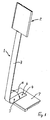
- Fig. 1
- die perspektivische Vorderansicht eines Ständers mit einem im Hochfor- mat angeordneten Informationsschild,
- Fig. 2
- die Rückenansicht des Ständers gemäß
Fig. 1 , - Fig. 3
- die Rückenansicht des Ständers gemäß
Fig. 1 nach einer Drehung des Informationsschildes um 90°, - Fig. 4
- eine Explosionsdarstellung der zur Befestigung des Informationsschildes am Träger verwendeten Mittel,
- Fig. 5
- einen Schnitt durch das Informationsschild und den Träger in der in
Fig. 1 dargestellten Position des Informationsschildes und - Fig. 6
- einen der
Fig. 5 entsprechenden Schnitt in einer Zwischenposition, die das Informationsschild während der Überführung aus der Position gemäßFig. 1 in die Position gemäßFig. 3 einnimmt. - In den
Figuren 1 bis 3 ist 1 ein aus einem flachen Aluminiumstreifen bestehender Träger für ein an seinem oberen Ende angeordnetes, ebenfalls aus Aluminium bestehendes Informationsschild 2. Der Träger 1 hat im Wesentlichen die Form eines L, dessen langer und kurzer Schenkel 3 und 4 einen Winkel α zueinander einnehmen, der kleiner ist als 90°. Der kurze Schenkel 4 des Trägers ist mittels zweier Schrauben 5 und 6 in einer Aussparung eines aus Stabilitätsgründen aus Grauguss bestehenden Fußteiles 7 befestigt. - In den
Figuren 2 und3 ist durch eine Pfeil 8 angedeutet, wie das Informationsschild 2 aus einer Längsformat-Position in einer Querformat-Position und zurück über führbar ist. - Bei dem Informationsschild 2 handelt es sich um ein Schild, das aus einem Grundkörper 9 und einer lösbar mit dem Grundkörper 9 verbundenen Abdeckscheibe 10 für einen zwischen dem Grundkörper 9 und der Abdeckscheibe 10 unterbringbaren Informationsträger 11 sowie aus Mitteln 12, 13 zum Zusammenhalt der vorgenannten drei Teile besteht (vgl.
Fig. 4 ). Ein Schild dieser Art ist aus derDE 20 2004 001 827 U1 bekannt. - Zur Befestigung des Informationsschildes 2 am Träger 1 dient ein Schwenkzapfen 14, der an seinem einen Ende einen Kopf 15 und seinem anderen Ende ein Gewinde 16 aufweist. Der Kopf 15 des Schwenkzapfens 14 findet Platz in einer von einer Nut gebildeten Vertiefung 17 des Informationsschildes 2.
- Zwischen dem Informationsschild 2 und dem Träger 1 sind zwei mit Bohrungen 18, 19 für den Schwenkzapfen 14 sowie mit Rastvorsprüngen 20 und Rastausnehmungen 21 versehene Kupplungsscheiben 22 und 23 angeordnet. An ihren den Rastvorsprüngen 20 und Rastausnehmungen,21 abgewandten Seiten weisen die Kupplungsscheiben 22, 23 außerdem Rastnocken 24 bzw. 25 auf, die in Rastlöcher 26 des Informationsschildes 2 und in als Rastlöcher nutzbare Bohrungen 27 am oberen Ende des Trägers 1 passen. Die Durchmesser der Bohrungen 27 sind hinreichend groß, um nicht nur die Rastnocken 24, sondern auch den Schwenkzapfen 14 aufzunehmen.
- Zusammengehalten werden die drehfest mit dem Informationsschild 2 und dem Träger 1 verbundenen Kupplungsscheiben 22, 23 durch eine Feder 28, deren eines Ende in einer Kammer 29 eines nach Art einer Hutmutter ausgebildeten Betätigungsknopfes 30 gelagert ist und deren anderes Ende sich über zwei Unterlegscheiben 31 und 32, von denen eine aus Kunststoff besteht, an der Rückseite des Trägers 1 abstützt. Die Feder 28 ist als Druckfeder ausgebildet und hält die Kupplungsscheiben 22, 23 normalerweise in der in
Figur 5 dargestellten Lage. Will der Benutzer das Informationsschild um 90° schwenken, drückt er die Hutmutter 30 in Richtung des Pfeiles 33 inFigur 6 und leitet in das Informationsschild 2 eine Drehbewegung in Richtung des Pfeiles 34 ein. Aufgrund der schrägen Seitenwände der Rastvorsprünge 20 und der Rastausnehmungen 21 entfernen sich die Kupplungsscheiben 22, 23 voneinander bis die Drehbewegung beendet ist und der äußere Druck auf den Betätigungsknopf 30 und die Feder 28 nicht mehr aufrechterhalten wird.
Claims (9)
- Ständer für ein Informationsschild mit einem Fußteil (7) und einem lösbar mit dem Fußteil (7) verbundenen Träger (1), der an seinem dem Fußteil (7) abgewandten Ende das Informationsschild trägt, dadurch gekennzeichnet, dass zwischen dem von einem im Wesentlichen L-förmigen Metallstreifen gebildeten Träger (1) und dem mit diesem über einen Schwenkzapfen (14) verbundenen Informationsschild (2) zwei durch eine Feder (28) gegeneinander gedrückte Kupplungsscheiben (22, 23) angeordnet sind, die Rastvorsprünge (20) und Rastausnehmungen (21) aufweisen, durch die das Informationsschild (2) in unterschiedlichen Positionen arretierbar ist.
- Ständer nach Anspruch 1, dadurch gekennzeichnet, dass ein Ende der zum Gegeneinanderdrücken der Kupplungsscheiben (22, 23) dienenden Feder (28) in einer Kammer (29) eines Betätigungsknopfes (30) gelagert ist, der auf ein über die Rückseite des Trägers (1) vorstehendes Gewinde (16) des Schwenkzapfens (14) geschraubt ist.
- Ständer nach Anspruch 2, dadurch gekennzeichnet, dass die als Druckfeder ausgebildete Feder (28) den Betätigungsknopf (30) bei eingekuppelten Kupplungsscheiben (22, 23) in einem Abstand von der Rückseite des Trägers (1) hält, der größer ist als die Höhe der Rastvorsprünge (20) der Kupplungsscheiben (22, 23).
- Ständer nach einem der Ansprüche 1 bis 3, dadurch gekennzeichnet, dass die eine Kupplungsscheibe (22) drehfest mit dem Informationsschild (2) und die andere Kupplungsscheibe (23) drehfest mit dem Träger (1) verbunden ist.
- Ständer nach Anspruch 4; dadurch gekennzeichnet, dass zur Herstellung der drehfesten Verbindung zwischen den Kupplungsscheiben (22, 23) und dem Informationsschild (2) sowie dem Träger (1) über die Rückseiten der Kupplungsscheiben (22, 23) vorstehende Rastnocken (24, 25) dienen, denen Rastlöcher, (26, 27) im Informationsschild (2) und im Träger (1) zugeordnet sind.
- Ständer nach einem der Ansprüche 1 bis 5, dadurch gekennzeichnet, dass der Träger (1) an seinem oberen Ende mit einer Reihe von zur Aufnahme des Schwenkzapfens (14) geeigneten Bohrungen (27) versehen ist.
- Ständer nach einem der Ansprüche 1 bis 6, dadurch gekennzeichnet, dass der Schwenkzapfen (14) drehfest mit dem Informationsschild (2) verbunden ist.
- Ständer nach einem der Ansprüche 1 bis 7, dadurch gekennzeichnet, dass das Informationsschild (2) an seiner Vorderseite mit einer Vertiefung (17) zur Aufnahme des Kopfes (15) des Schwenkzapfens (14) versehen ist.
- Ständer nach einem der Ansprüche 1 bis 8, dadurch gekennzeichnet, dass der Träger (1) sowie das Informationsschild (2) aus Leichtmetall bestehen, während das Fußteil (7) als Graugussteil ausgebildet ist.
Applications Claiming Priority (2)
| Application Number | Priority Date | Filing Date | Title |
|---|---|---|---|
| DE102005058123A DE102005058123B4 (de) | 2005-11-29 | 2005-11-29 | Ständer für ein Informationsschild |
| PCT/EP2006/011313 WO2007062786A1 (de) | 2005-11-29 | 2006-11-25 | Ständer für ein informationsschild |
Publications (2)
| Publication Number | Publication Date |
|---|---|
| EP1955310A1 EP1955310A1 (de) | 2008-08-13 |
| EP1955310B1 true EP1955310B1 (de) | 2010-02-10 |
Family
ID=37744598
Family Applications (1)
| Application Number | Title | Priority Date | Filing Date |
|---|---|---|---|
| EP20060829123 Not-in-force EP1955310B1 (de) | 2005-11-29 | 2006-11-25 | Ständer für ein informationsschild |
Country Status (6)
| Country | Link |
|---|---|
| US (1) | US8069596B2 (de) |
| EP (1) | EP1955310B1 (de) |
| AT (1) | ATE457508T1 (de) |
| DE (2) | DE102005058123B4 (de) |
| RU (1) | RU2402825C2 (de) |
| WO (1) | WO2007062786A1 (de) |
Cited By (1)
| Publication number | Priority date | Publication date | Assignee | Title |
|---|---|---|---|---|
| CN105810089A (zh) * | 2016-04-27 | 2016-07-27 | 国网山东省电力公司菏泽供电公司 | 一种标示牌 |
Families Citing this family (3)
| Publication number | Priority date | Publication date | Assignee | Title |
|---|---|---|---|---|
| US8613430B2 (en) * | 2009-04-01 | 2013-12-24 | Firestone Industrial Products Company, Llc | Gas spring assembly and suspension system including same |
| US20120080581A1 (en) * | 2010-10-04 | 2012-04-05 | Chun Yuan Chang | Rotary reading stand |
| DE102021121931A1 (de) * | 2021-08-24 | 2023-03-02 | "Durable" Hunke & Jochheim Gmbh & Co. Kommanditgesellschaft | Aufsteller zum Halten eines Informationsträgers |
Family Cites Families (12)
| Publication number | Priority date | Publication date | Assignee | Title |
|---|---|---|---|---|
| US1374471A (en) * | 1921-04-12 | Traffic-signal | ||
| US2073403A (en) * | 1935-11-23 | 1937-03-09 | Abraham G Goldberg | Display device |
| US3221429A (en) * | 1963-08-26 | 1965-12-07 | Promotional Advertising Associ | Display apparatus |
| DE3304180A1 (de) * | 1983-02-08 | 1984-08-09 | Rudolf Dipl.-Ing. 6360 Friedberg Weiner | Daten- und infotafel fuer arbeitsplaetze |
| AT386693B (de) * | 1983-07-18 | 1988-09-26 | Streif Walter | Befestigungsvorrichtung fuer schilder u. dgl. |
| DE9402735U1 (de) * | 1994-02-19 | 1994-04-07 | Oechsle Kunststofftechnik GmbH, 89340 Leipheim | Fußteil für Plakatständer |
| JP2000181353A (ja) * | 1998-12-17 | 2000-06-30 | Kawajun Kk | 表示具 |
| DE19913865A1 (de) * | 1999-03-26 | 2000-09-28 | Joachim Glas | Schirmständer |
| DE29921990U1 (de) * | 1999-12-14 | 2000-02-17 | Fehlbaum & Co., Muttenz | Haltevorrichtung für einen plakatförmigen Informationsträger |
| EP1711929B1 (de) * | 2004-02-02 | 2008-11-05 | Durable Hunke & Jochheim GmbH & Co. KG. | Schild, insbesondere informationsschild |
| DE202004001827U1 (de) * | 2004-02-02 | 2004-04-08 | "Durable" Hunke & Jochheim Gmbh & Co. Kg | Schild, insbesondere Informationsschild |
| WO2006028394A2 (en) * | 2004-09-09 | 2006-03-16 | Rodier Advertising (1986) Limited | An orientation device of or for a rotatable display box |
-
2005
- 2005-11-29 DE DE102005058123A patent/DE102005058123B4/de not_active Expired - Lifetime
-
2006
- 2006-11-25 EP EP20060829123 patent/EP1955310B1/de not_active Not-in-force
- 2006-11-25 US US12/085,622 patent/US8069596B2/en not_active Expired - Fee Related
- 2006-11-25 RU RU2008126258A patent/RU2402825C2/ru active
- 2006-11-25 WO PCT/EP2006/011313 patent/WO2007062786A1/de not_active Ceased
- 2006-11-25 AT AT06829123T patent/ATE457508T1/de active
- 2006-11-25 DE DE200650006130 patent/DE502006006130D1/de active Active
Cited By (2)
| Publication number | Priority date | Publication date | Assignee | Title |
|---|---|---|---|---|
| CN105810089A (zh) * | 2016-04-27 | 2016-07-27 | 国网山东省电力公司菏泽供电公司 | 一种标示牌 |
| CN105810089B (zh) * | 2016-04-27 | 2018-09-28 | 国网山东省电力公司菏泽供电公司 | 一种标示牌 |
Also Published As
| Publication number | Publication date |
|---|---|
| DE102005058123B4 (de) | 2007-07-19 |
| EP1955310A1 (de) | 2008-08-13 |
| DE102005058123A1 (de) | 2007-05-31 |
| RU2402825C2 (ru) | 2010-10-27 |
| US20100024267A1 (en) | 2010-02-04 |
| US8069596B2 (en) | 2011-12-06 |
| DE502006006130D1 (de) | 2010-03-25 |
| WO2007062786A1 (de) | 2007-06-07 |
| ATE457508T1 (de) | 2010-02-15 |
| RU2008126258A (ru) | 2010-01-10 |
Similar Documents
| Publication | Publication Date | Title |
|---|---|---|
| DE102016105981B4 (de) | Unterlegeinrichtung für eine Silikonpistole und Silikonpistole | |
| DE60101167T2 (de) | Verriegelungsvorrichtung bedienbar ohne werkzeug | |
| DE10256548A1 (de) | Diebstahlsicherung für PDAs | |
| DE102010000950A1 (de) | Halterungsmechanismus | |
| DE202020103327U1 (de) | Schnelllöseanordnung und Träger | |
| WO2017041914A1 (de) | Halter für flache in etwa rechteckige geräte wie tablet-computer oder smartphones | |
| EP0670405A1 (de) | Türaufhängevorrichtung für eine Vitrine zur Zurschaustellung von Gegenständen | |
| DE202007007021U1 (de) | Halterung für Digitalgerät | |
| DE60200811T2 (de) | Elektrischer rotierender Rasierer | |
| DE9113337U1 (de) | Behälter für Gebrauchsgegenstände, insbesondere Schreibgeräte | |
| DE202010010893U1 (de) | Halter für ein elektronisches Gerät | |
| DE102005058123B4 (de) | Ständer für ein Informationsschild | |
| DE202005019007U1 (de) | Ständer für ein Informationsschild | |
| DE102021112229A1 (de) | Rechteckige Tafel mit einem Tafelblatt | |
| DE1948574C3 (de) | Haltevorrichtung für ein elektronisches Musikinstrument | |
| DE102006002550B4 (de) | Ständer mit einem Halter für Wendetafeln, Wendetaschen oder Wendehüllen | |
| DE2154910C3 (de) | Zeichentisch | |
| EP0202446A1 (de) | Neigevorrichtung für Sichtgeräte | |
| DE102005015363B3 (de) | Haltevorrichtung für Zettel oder dergleichen | |
| DE102008003506A1 (de) | Kalender | |
| DE202005005863U1 (de) | Mehrzweck-Befestigungsstütze | |
| DE202025107787U1 (de) | Fahrzeugmontierter Fahrradträger und dessen Kennzeichenwendevorrichtung | |
| DE29620856U1 (de) | Revolverlochzange | |
| DE202023001499U1 (de) | Mehrteiliger Fingerring mit Dreh- und Kippelement | |
| DE202015105283U1 (de) | Korb für Wasserflaschen zum Befestigen in beiden Richtungen auf zwei gegenüberliegenden Seiten |
Legal Events
| Date | Code | Title | Description |
|---|---|---|---|
| PUAI | Public reference made under article 153(3) epc to a published international application that has entered the european phase |
Free format text: ORIGINAL CODE: 0009012 |
|
| 17P | Request for examination filed |
Effective date: 20080409 |
|
| AK | Designated contracting states |
Kind code of ref document: A1 Designated state(s): AT BE BG CH CY CZ DE DK EE ES FI FR GB GR HU IE IS IT LI LT LU LV MC NL PL PT RO SE SI SK TR |
|
| GRAP | Despatch of communication of intention to grant a patent |
Free format text: ORIGINAL CODE: EPIDOSNIGR1 |
|
| GRAS | Grant fee paid |
Free format text: ORIGINAL CODE: EPIDOSNIGR3 |
|
| GRAA | (expected) grant |
Free format text: ORIGINAL CODE: 0009210 |
|
| AK | Designated contracting states |
Kind code of ref document: B1 Designated state(s): AT BE BG CH CY CZ DE DK EE ES FI FR GB GR HU IE IS IT LI LT LU LV MC NL PL PT RO SE SI SK TR |
|
| REG | Reference to a national code |
Ref country code: GB Ref legal event code: FG4D Free format text: NOT ENGLISH |
|
| REG | Reference to a national code |
Ref country code: CH Ref legal event code: EP |
|
| REG | Reference to a national code |
Ref country code: IE Ref legal event code: FG4D |
|
| REF | Corresponds to: |
Ref document number: 502006006130 Country of ref document: DE Date of ref document: 20100325 Kind code of ref document: P |
|
| REG | Reference to a national code |
Ref country code: NL Ref legal event code: T3 |
|
| REG | Reference to a national code |
Ref country code: SE Ref legal event code: TRGR |
|
| LTIE | Lt: invalidation of european patent or patent extension |
Effective date: 20100210 |
|
| PG25 | Lapsed in a contracting state [announced via postgrant information from national office to epo] |
Ref country code: ES Free format text: LAPSE BECAUSE OF FAILURE TO SUBMIT A TRANSLATION OF THE DESCRIPTION OR TO PAY THE FEE WITHIN THE PRESCRIBED TIME-LIMIT Effective date: 20100521 Ref country code: IS Free format text: LAPSE BECAUSE OF FAILURE TO SUBMIT A TRANSLATION OF THE DESCRIPTION OR TO PAY THE FEE WITHIN THE PRESCRIBED TIME-LIMIT Effective date: 20100610 Ref country code: LT Free format text: LAPSE BECAUSE OF FAILURE TO SUBMIT A TRANSLATION OF THE DESCRIPTION OR TO PAY THE FEE WITHIN THE PRESCRIBED TIME-LIMIT Effective date: 20100210 Ref country code: PT Free format text: LAPSE BECAUSE OF FAILURE TO SUBMIT A TRANSLATION OF THE DESCRIPTION OR TO PAY THE FEE WITHIN THE PRESCRIBED TIME-LIMIT Effective date: 20100611 |
|
| PG25 | Lapsed in a contracting state [announced via postgrant information from national office to epo] |
Ref country code: SI Free format text: LAPSE BECAUSE OF FAILURE TO SUBMIT A TRANSLATION OF THE DESCRIPTION OR TO PAY THE FEE WITHIN THE PRESCRIBED TIME-LIMIT Effective date: 20100210 Ref country code: PL Free format text: LAPSE BECAUSE OF FAILURE TO SUBMIT A TRANSLATION OF THE DESCRIPTION OR TO PAY THE FEE WITHIN THE PRESCRIBED TIME-LIMIT Effective date: 20100210 Ref country code: LV Free format text: LAPSE BECAUSE OF FAILURE TO SUBMIT A TRANSLATION OF THE DESCRIPTION OR TO PAY THE FEE WITHIN THE PRESCRIBED TIME-LIMIT Effective date: 20100210 Ref country code: FI Free format text: LAPSE BECAUSE OF FAILURE TO SUBMIT A TRANSLATION OF THE DESCRIPTION OR TO PAY THE FEE WITHIN THE PRESCRIBED TIME-LIMIT Effective date: 20100210 |
|
| REG | Reference to a national code |
Ref country code: IE Ref legal event code: FD4D |
|
| PG25 | Lapsed in a contracting state [announced via postgrant information from national office to epo] |
Ref country code: GR Free format text: LAPSE BECAUSE OF FAILURE TO SUBMIT A TRANSLATION OF THE DESCRIPTION OR TO PAY THE FEE WITHIN THE PRESCRIBED TIME-LIMIT Effective date: 20100511 Ref country code: CY Free format text: LAPSE BECAUSE OF FAILURE TO SUBMIT A TRANSLATION OF THE DESCRIPTION OR TO PAY THE FEE WITHIN THE PRESCRIBED TIME-LIMIT Effective date: 20100210 Ref country code: IE Free format text: LAPSE BECAUSE OF FAILURE TO SUBMIT A TRANSLATION OF THE DESCRIPTION OR TO PAY THE FEE WITHIN THE PRESCRIBED TIME-LIMIT Effective date: 20100210 Ref country code: EE Free format text: LAPSE BECAUSE OF FAILURE TO SUBMIT A TRANSLATION OF THE DESCRIPTION OR TO PAY THE FEE WITHIN THE PRESCRIBED TIME-LIMIT Effective date: 20100210 Ref country code: RO Free format text: LAPSE BECAUSE OF FAILURE TO SUBMIT A TRANSLATION OF THE DESCRIPTION OR TO PAY THE FEE WITHIN THE PRESCRIBED TIME-LIMIT Effective date: 20100210 |
|
| PG25 | Lapsed in a contracting state [announced via postgrant information from national office to epo] |
Ref country code: SK Free format text: LAPSE BECAUSE OF FAILURE TO SUBMIT A TRANSLATION OF THE DESCRIPTION OR TO PAY THE FEE WITHIN THE PRESCRIBED TIME-LIMIT Effective date: 20100210 Ref country code: CZ Free format text: LAPSE BECAUSE OF FAILURE TO SUBMIT A TRANSLATION OF THE DESCRIPTION OR TO PAY THE FEE WITHIN THE PRESCRIBED TIME-LIMIT Effective date: 20100210 Ref country code: BG Free format text: LAPSE BECAUSE OF FAILURE TO SUBMIT A TRANSLATION OF THE DESCRIPTION OR TO PAY THE FEE WITHIN THE PRESCRIBED TIME-LIMIT Effective date: 20100510 |
|
| PLBE | No opposition filed within time limit |
Free format text: ORIGINAL CODE: 0009261 |
|
| STAA | Information on the status of an ep patent application or granted ep patent |
Free format text: STATUS: NO OPPOSITION FILED WITHIN TIME LIMIT |
|
| 26N | No opposition filed |
Effective date: 20101111 |
|
| PG25 | Lapsed in a contracting state [announced via postgrant information from national office to epo] |
Ref country code: DK Free format text: LAPSE BECAUSE OF FAILURE TO SUBMIT A TRANSLATION OF THE DESCRIPTION OR TO PAY THE FEE WITHIN THE PRESCRIBED TIME-LIMIT Effective date: 20100210 |
|
| PG25 | Lapsed in a contracting state [announced via postgrant information from national office to epo] |
Ref country code: IT Free format text: LAPSE BECAUSE OF FAILURE TO SUBMIT A TRANSLATION OF THE DESCRIPTION OR TO PAY THE FEE WITHIN THE PRESCRIBED TIME-LIMIT Effective date: 20100210 |
|
| PG25 | Lapsed in a contracting state [announced via postgrant information from national office to epo] |
Ref country code: MC Free format text: LAPSE BECAUSE OF NON-PAYMENT OF DUE FEES Effective date: 20101130 |
|
| REG | Reference to a national code |
Ref country code: CH Ref legal event code: PL |
|
| PG25 | Lapsed in a contracting state [announced via postgrant information from national office to epo] |
Ref country code: CH Free format text: LAPSE BECAUSE OF NON-PAYMENT OF DUE FEES Effective date: 20101130 Ref country code: LI Free format text: LAPSE BECAUSE OF NON-PAYMENT OF DUE FEES Effective date: 20101130 |
|
| PGFP | Annual fee paid to national office [announced via postgrant information from national office to epo] |
Ref country code: DE Payment date: 20110510 Year of fee payment: 5 |
|
| REG | Reference to a national code |
Ref country code: DE Ref legal event code: R119 Ref document number: 502006006130 Country of ref document: DE Effective date: 20120601 |
|
| PG25 | Lapsed in a contracting state [announced via postgrant information from national office to epo] |
Ref country code: HU Free format text: LAPSE BECAUSE OF FAILURE TO SUBMIT A TRANSLATION OF THE DESCRIPTION OR TO PAY THE FEE WITHIN THE PRESCRIBED TIME-LIMIT Effective date: 20100811 Ref country code: LU Free format text: LAPSE BECAUSE OF NON-PAYMENT OF DUE FEES Effective date: 20101125 |
|
| PG25 | Lapsed in a contracting state [announced via postgrant information from national office to epo] |
Ref country code: TR Free format text: LAPSE BECAUSE OF FAILURE TO SUBMIT A TRANSLATION OF THE DESCRIPTION OR TO PAY THE FEE WITHIN THE PRESCRIBED TIME-LIMIT Effective date: 20100210 |
|
| PG25 | Lapsed in a contracting state [announced via postgrant information from national office to epo] |
Ref country code: DE Free format text: LAPSE BECAUSE OF NON-PAYMENT OF DUE FEES Effective date: 20120601 |
|
| REG | Reference to a national code |
Ref country code: FR Ref legal event code: PLFP Year of fee payment: 10 |
|
| REG | Reference to a national code |
Ref country code: FR Ref legal event code: PLFP Year of fee payment: 11 |
|
| REG | Reference to a national code |
Ref country code: FR Ref legal event code: PLFP Year of fee payment: 12 |
|
| PGFP | Annual fee paid to national office [announced via postgrant information from national office to epo] |
Ref country code: NL Payment date: 20191120 Year of fee payment: 14 |
|
| PGFP | Annual fee paid to national office [announced via postgrant information from national office to epo] |
Ref country code: AT Payment date: 20191121 Year of fee payment: 14 |
|
| REG | Reference to a national code |
Ref country code: NL Ref legal event code: MM Effective date: 20201201 |
|
| REG | Reference to a national code |
Ref country code: AT Ref legal event code: MM01 Ref document number: 457508 Country of ref document: AT Kind code of ref document: T Effective date: 20201125 |
|
| PG25 | Lapsed in a contracting state [announced via postgrant information from national office to epo] |
Ref country code: AT Free format text: LAPSE BECAUSE OF NON-PAYMENT OF DUE FEES Effective date: 20201125 Ref country code: NL Free format text: LAPSE BECAUSE OF NON-PAYMENT OF DUE FEES Effective date: 20201201 |
|
| PGFP | Annual fee paid to national office [announced via postgrant information from national office to epo] |
Ref country code: SE Payment date: 20211118 Year of fee payment: 16 Ref country code: GB Payment date: 20211119 Year of fee payment: 16 Ref country code: FR Payment date: 20211122 Year of fee payment: 16 |
|
| PGFP | Annual fee paid to national office [announced via postgrant information from national office to epo] |
Ref country code: BE Payment date: 20211118 Year of fee payment: 16 |
|
| REG | Reference to a national code |
Ref country code: SE Ref legal event code: EUG |
|
| GBPC | Gb: european patent ceased through non-payment of renewal fee |
Effective date: 20221125 |
|
| REG | Reference to a national code |
Ref country code: BE Ref legal event code: MM Effective date: 20221130 |
|
| PG25 | Lapsed in a contracting state [announced via postgrant information from national office to epo] |
Ref country code: SE Free format text: LAPSE BECAUSE OF NON-PAYMENT OF DUE FEES Effective date: 20221126 |
|
| PG25 | Lapsed in a contracting state [announced via postgrant information from national office to epo] |
Ref country code: GB Free format text: LAPSE BECAUSE OF NON-PAYMENT OF DUE FEES Effective date: 20221125 |
|
| PG25 | Lapsed in a contracting state [announced via postgrant information from national office to epo] |
Ref country code: FR Free format text: LAPSE BECAUSE OF NON-PAYMENT OF DUE FEES Effective date: 20221130 Ref country code: BE Free format text: LAPSE BECAUSE OF NON-PAYMENT OF DUE FEES Effective date: 20221130 |