EP1953455A1 - Système d'injection de carburant à double injecteur - Google Patents
Système d'injection de carburant à double injecteur Download PDFInfo
- Publication number
- EP1953455A1 EP1953455A1 EP08150474A EP08150474A EP1953455A1 EP 1953455 A1 EP1953455 A1 EP 1953455A1 EP 08150474 A EP08150474 A EP 08150474A EP 08150474 A EP08150474 A EP 08150474A EP 1953455 A1 EP1953455 A1 EP 1953455A1
- Authority
- EP
- European Patent Office
- Prior art keywords
- injector
- injection system
- fuel
- air intake
- air
- Prior art date
- Legal status (The legal status is an assumption and is not a legal conclusion. Google has not performed a legal analysis and makes no representation as to the accuracy of the status listed.)
- Granted
Links
Images


Classifications
-
- F—MECHANICAL ENGINEERING; LIGHTING; HEATING; WEAPONS; BLASTING
- F23—COMBUSTION APPARATUS; COMBUSTION PROCESSES
- F23R—GENERATING COMBUSTION PRODUCTS OF HIGH PRESSURE OR HIGH VELOCITY, e.g. GAS-TURBINE COMBUSTION CHAMBERS
- F23R3/00—Continuous combustion chambers using liquid or gaseous fuel
- F23R3/28—Continuous combustion chambers using liquid or gaseous fuel characterised by the fuel supply
- F23R3/34—Feeding into different combustion zones
- F23R3/343—Pilot flames, i.e. fuel nozzles or injectors using only a very small proportion of the total fuel to insure continuous combustion
Definitions
- the invention relates to a fuel injection system in a turbomachine combustion chamber, and a turbomachine combustion chamber equipped with such a system.
- the invention is intended for any type of turbomachine, terrestrial or aeronautical, and more particularly to aircraft turbojets.
- a turbojet combustion chamber is generally annular in shape, centered on an axis X corresponding to the axis of rotation of the turbojet engine. It comprises two coaxial annular walls (or ferrules) of X axis, and a chamber bottom disposed between said walls, in the upstream region of said chamber, the upstream and the downstream being defined with respect to the normal direction of circulation of the gas inside the room. Said walls and the chamber bottom define the combustion chamber of the chamber.
- a plurality of fuel injection systems in the chamber are attached to the chamber bottom and evenly distributed about the X axis.
- the most common injection systems include a single fuel injector.
- the design (i.e. shape, structure, choice of materials %) of combustion chambers equipped with single injector systems is now perfectly mastered and hereinafter referred to as conventional design chambers.
- each injection system is fixed and positioned within a single hole provided for this purpose in the chamber bottom, so that the assembly of the injection system is relatively simple.
- the temperature profile at the chamber outlet remains centered on a circle of determined diameter around the X axis, regardless of the operating speed of the turbojet engine. Such a temperature profile simplifies the design of the turbojet parts located downstream of the chamber.
- double injector fuel injection systems In order to limit the emission of gaseous pollutants, double injector fuel injection systems have been developed.
- the two injectors make it possible to create two combustion zones, one optimized for the idle speed of the turbojet and the other for the full throttle.
- the document FR 2 706 021 describes an annular turbojet combustion chamber, equipped with several injection systems with double injector.
- the chamber is centered on an X axis and the injection systems are distributed around the X axis, each system comprising two injectors arranged one after the other in a radial direction with respect to the X axis.
- a first row of N injectors is arranged in a circle of diameter d, about the axis X
- a second row of N injectors is arranged in a circle of diameter D, upper at d, around the X axis.
- the injection system with double injector FR 2 706 021 has the disadvantage of being difficult to mount since it is necessary to position and fix each injector on the chamber bottom.
- the design of the combustion chamber is more complex and much less controlled than the aforementioned conventional design (which results in particular in difficulties to ensure the thermal resistance and the life of some elements of the chamber).
- the temperature profile at the chamber outlet varies significantly as a function of the turbojet engine operating speed and, in particular, this profile does not remain centered on a circle of determined diameter around the X axis. complicates the design of the turbojet parts located downstream of the combustion chamber.
- the object of the invention is to propose a fuel injection system which is not very polluting and which can be used with a combustion chamber of conventional design, that is to say a chamber of the type that is equipped with combustion systems. injection to a single injector.
- the injection system of the invention therefore comprises two injectors, which makes it possible to adapt the richness of the air / fuel mixture to the operating speed of the turbojet engine and to limit the emission of pollutant gases.
- this type of system can be adapted to a conventional design chamber with, in particular, a single orifice in the chamber bottom for each injection system.
- the second injector has a circular injection slot surrounding the first injector and, according to a second embodiment, it has a plurality of injection orifices arranged in a circle around the first injector.
- the first injector, the first air intake passage and the second injector belong to a first assembly intended to be mounted on a second assembly comprising the second air intake passage, the second assembly being intended to be mounted on the combustion chamber.
- the second set then serves as a guide for mounting the first.
- the relative position of the first and second injectors is generally imposed by the conformation of the first set and therefore does not have to be adjusted during assembly.
- the second assembly is mounted on the chamber bottom while maintaining a possibility of radial displacement around the injection axis I of the first injector, and can move along this axis relative to the first set, while remaining centered vis-à-vis the latter.
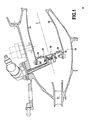
- combustion chamber 10 of the figure 1 is represented in its environment, inside a turbojet engine.
- This chamber 10 is annular, centered on the axis X which is also the axis of rotation of the turbojet engine.
- This combustion chamber is called axial because it is oriented substantially along the X axis.
- the invention could be applied to other types of turbomachines and other types of chambers, in particular so-called radial return combustion chambers, that is to say combustion chambers bent a portion of which is oriented substantially radially relative to the axis of rotation of the turbojet engine.
- the combustion chamber 10 comprises two internal and external 12 annular walls (or ferrules). These walls 12, 14 are spaced apart and positioned coaxially around the axis X. These walls 12, 14 are interconnected by a bottom of chamber 16 disposed between them, in the upstream region of the chamber 10. The walls 12, 14 and the bottom 16 delimit between them, the combustion chamber of the chamber 10.
- the chamber bottom 16 has a plurality of openings 18 evenly distributed around the axis of rotation X.
- the chamber 10 also comprises baffles 19 mounted on the chamber bottom 16, at the periphery of the openings 18, so as to protect the bottom 16 of the high temperatures reached during the combustion.
- a fuel injection system 20 Inside each opening 18 is mounted a fuel injection system 20 according to the invention. This system 20 is shown in detail on the figures 2 and 3 .
- combustion chamber 10 is of conventional design, that is to say that its general shape, its structure, etc. are comparable to those of a combustion chamber equipped with injection systems with a single injector.
- the combustion chamber 10 has been designed taking into account the particularities of the injection systems 20 and, in particular, the orifices 18 are of a size adapted to that of the injection systems 20 (larger in diameter than the systems conventional injection systems 20).
- Each injection system 20 comprises, in its center, a first fuel injector 22 (also called pilot injector) for injecting fuel along an injection axis I.
- the injection system 20 comprises, around the first injector 22 and in this order: a first air intake passage 24, an air intake duct 26, a second fuel injector 28, and a second air intake passage 30.
- the injection system 20 has a substantial symmetry of revolution about the axis I, the elements constituting it being of generally annular shape, and distributed coaxially around this axis I.
- the first and second air intake passages 24, 30 are air auger, that is to say, annular passages for printing a rotational movement (around the axis I) to the air that passes through them.
- the compressed air passing through the intake passages 24 and 30 comes from the diffuser 17 of the turbojet engine (see FIG. Fig. 1 ).
- the first and second injectors 22 and 28 are respectively fueled by supply lines (or ramps) 32 and 38.
- the second injector 28 is fed by a single line 38.
- the second Injector 28 can be fed by several pipes connected at different points of the circumference of the injector 28.
- the first and second injectors 22 and 28 may be powered with the same or different fuels.
- a specific arrangement for the use of hydrogen can be made for the second injector 28.
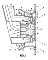
- the first injector 22 makes it possible to inject a first cloud of fuel 42 (see figure 3 ) at the center of the injection system 20, via an injection port 23 centered on the axis I.
- the fuel cloud 42 is generally conical, centered on the axis I.
- the second injector 28 is of annular shape and makes it possible to inject, via a circular injection slot 29 centered on the axis I, a second cloud of fuel 48 (see FIG. figure 3 ).
- This second fuel cloud 48 is of generally annular shape, substantially centered on the axis I, and surrounds the first cloud 42.
- the fuel emitted by the injectors 22 and 28 is mixed with air, this air coming from the air intake passages 24 and 30.
- These passages 24 and 30 are respectively located around the injectors 22 and 28, upstream of the injection port 23 and the injection slot 29.
- the second injector 28 is also configured to print a rotational movement (about the axis I) to the fuel cloud 48.
- the rotational movement of the air from the passage intake 30 can be in the same direction (co-rotating) or opposite direction (counter-rotating) to that of the fuel cloud 48.
- the first air intake passage 24 is delimited between inner and outer 43 and generally annular walls, centered on the axis I.
- the inner wall 43 envelops the first injector 22.
- the outer wall 44 extends downstream by a diverging wall 45, that is to say a wall defining a generally frustoconical duct, or bowl 61, whose section increases in the direction of flow of the first mixture air / fuel (ie from upstream to downstream).
- the air intake duct 26 is defined between the walls 44 and 45, on the one hand, and a wall 46, on the other hand, the wall 46 surrounding the ducts. walls 44 and 45. Radial structural arms 47 connect the walls 44 and 46 and keep them apart.
- the injection system 20 has a recess 49 upstream of the duct 26 and the passage 24.
- this recess is cylindrical, of external diameter substantially corresponding to that of the conduit 26. Only the supply duct 32 of the first injector 22 passes through this recess 49.
- the air intake duct 26 comprises a first series of outlet orifices 62 passing through the divergent wall 45, at the downstream end of this wall, these orifices 62 being arranged in a circle around the first injector 22 (in downstream of it). It further comprises a second series of outlet orifices 63 passing through the diverging wall 45 upstream of said first series of orifices 62, these orifices 63 being arranged in a circle around the first injector (downstream thereof) .
- the orifices 62 and 63 are regularly distributed around the first injector 22.
- the second injector 28 is arranged around the wall 46.
- the first injector 22, the air intake passage 24, the bowl 61, the conduit 26 and the second injector 28 are all joined within a first assembly 51 defined by an outer wall 50.
- This wall 50 is connected at the downstream ends of the walls 45 and 46, so that it contributes to delimiting a housing for the second injector 28 with the wall 46, and to delimit the duct 26 with the walls 44, 45 and 46.
- the first assembly 51 is surrounded by a second assembly 52.
- These assemblies 51 and 52 are mounted one after the other on the bottom wall 16 of the combustion chamber 10: first, the assembly 52 is mounted on this bottom wall, inside the orifice 18, then the assembly 51 is mounted inside the assembly 52.
- the second assembly 52 comprises two inner annular walls 53 and outer 54, mutually spaced and delimiting between them the second air intake passage 30.
- the outer wall 54 and the inner wall 53 are flared upstream so as not to hinder the assembly of the assembly 51 on the assembly 52, this assembly being performed by the rear of the assembly 52 (ie from upstream to downstream).
- the outer wall 54 extending downstream by a cylindrical wall 55, then by a diverging wall 56.
- the cylindrical wall 55 forms with the outer wall 50 an annular channel 57 inside which is injected the cloud of fuel 48.
- This channel 57 is located in the extension of the second air intake passage 30, downstream of that -this.
- the diverging wall 56 (in the manner of the wall 45) forms a frustoconical duct flared downstream, or bowl 71.
- This diverging wall 56 is traversed, at its downstream end, by a series of orifices 72 arranged in circle around the second injector 28, downstream thereof.
- the term “idle” module denotes the assembly comprising the first fuel injector 22 and the first air intake passage 24, and by "full gas” module the assembly comprising the second fuel injector 28 and the second air intake passage 30. Note that these modules do not correspond with the sets 51 and 52 described above. It will also be noted that these modules are arranged coaxially around the injection axis I.
- an "idle” circuit comprising the supply duct 32 and the first injector 22, this circuit opening at the center of the injection system via the injection orifice 23; and a “full-gas” circuit comprising the supply duct 38 and the second injector 28, this circuit opening at the periphery of the injection system, via the injection slot 29.
- the regulation of the operation of the idle and full throttle modules and, in particular, the evolution of the distribution of the fuel between the two modules as a function of the operating speed of the turbojet, are defined so as to limit the emissions of toxic gases on the whole. engine operation.
- both modules may be used.
- the idle module operates alone. Beyond a scheme corresponding to a thrust 10 to 30% thrust full throttle, both modules operate with adequate fuel distribution to limit emissions of toxic gases.
- the first injector 22 injects the first cloud of fuel 42.
- the first air intake passage 26 generates a swirling air flow which takes up the injected fuel and helps to ensure the spraying and mixing.
- An air film f2 with a gyratory component is generated by the second set of orifices 63 of the air intake duct 26.
- This f2 air film serves to: protect the diverging wall 45 against the risks of coking; to control the vortex precession movements generated by the first air intake passage 24, this movement being the source of instability of combustion; to control the axial position of the recirculation zone of the idle module so as to eliminate the risk of "flashback", to control the heat transfer at the end of the injector 22 and thus reduce the risk of coking of the circuit of fuel to the nose of the injector 22, and improve the propagation of the flame of the idle module to the full throttle module, during the transition between idle and full throttle.
- An air film f1 is generated by the first series of orifices 62 of the air intake duct 26.
- This function of the air film f1 is: to control the radial expansion of the fuel cloud 42 from the first injector 22, and to isolate it from the air coming from the second air intake passage 30, which makes it possible to maintain a level of richness sufficient to limit the formation of CO / CHx at idle; and to dampen the instabilities of combustion between the two modules.
- the orifices 62 of the first series may all be of identical size, or of variable size (by sector) in order to improve the compromise between the performances in idle speed which require to isolate the combustion zone of the first air mixture. fuel, and the operability that is favored by an intercommunication between the idle zone and the full gas zone to ensure the propagation of the flame.
- the injection of the second fuel cloud 48 can be done via a circular slot 29, as in the example of the figures, or via a plurality of holes distributed in a circle around the first injector 22.
- the cloud fuel 48 can be injected in a co- or contra-rotational manner with respect to the gyratory flow from the second air intake passage 30.
- the axial-radial inclination of the second air intake passage 30 allows to deliver an air flow whose speed field promotes penetration and a homogeneous mixture of the fuel, which allows for the second air / fuel mixture in the channel 57.
- the bowl 71 is attached to the chamber bottom 16 and is crossed, upstream of the series of orifices 72, by one or more other series of orifices (not shown) which make it possible to take back the trickling fuel in wall 54 and thus to improve the qualities of the mixture produced in the channel 57.
- the air film f3, resulting from the series of orifices 72, makes it possible to control the radial expansion of the second air / fuel mixture, which makes it possible to limit the interactions with the walls of the combustion chamber, detrimental to its behavior. thermal.
- the orifices 72 may all be of identical size or of variable size (by sector) to ensure both a control of the expansion of the second air / fuel mixture towards the walls of the chamber and to promote the propagation of the flame between adjacent full-gas modules, especially during an ignition phase.
- the scheme of the figure 4 represents the different flow zones generated by the injection system of the Figures 1 to 3 .
- the idle module generates a recirculation zone A located around the injection axis I.
- the characteristics of this recirculation zone are determined by the size of the bowl. 61 and the air flow of the idle module. They will determine the performance of the chamber in terms of re-ignition, stability and idling.
- the second air intake passage 30 which belongs to the full-gas module, generates a direct swirling flow in the flow zone B, isolated from the recirculation zone A by the air film f1 from the first series of outlet orifices 62 of the air supply duct 26, this film of air f1 limiting the shear and therefore the mixing between the zones A and B.
- the presence of the series of orifices 72 of the bowl 71 of the full-gas module avoids the interaction of the gases of the flow zone B with the walls of the combustion chamber 10.
- the full-gas module generates a recirculation zone C located on either side of each injection system 20, and between the injection systems, at the bottom of the chamber.
- the full-gas module has a wide range of stability allowing a significant adjustment latitude with respect to the transition from idling to full throttle. It should be noted that the slow-moving and full-throttle flows mix in the downstream part of the combustion chamber, in the zone marked D.
- the idle module and the full-throttle module are carbureted, the fuel distribution being chosen so as to achieve a lean combustion, thus low NOx and smoke production on both modules.
Landscapes
- Engineering & Computer Science (AREA)
- Chemical & Material Sciences (AREA)
- Combustion & Propulsion (AREA)
- Mechanical Engineering (AREA)
- General Engineering & Computer Science (AREA)
- Fuel-Injection Apparatus (AREA)
Abstract
Description
- L'invention concerne un système d'injection de carburant dans une chambre de combustion de turbomachine, et une chambre de combustion de turbomachine équipée d'un tel système. L'invention se destine à tout type de turbomachine, terrestre ou aéronautique, et plus particulièrement aux turboréacteurs d'avions.
- Une chambre de combustion de turboréacteur est généralement de forme annulaire, centrée sur un axe X correspondant à l'axe de rotation du turboréacteur. Elle comprend deux parois annulaires (ou viroles) coaxiales d'axe X, et un fond de chambre disposé entre lesdites parois, dans la région amont de ladite chambre, l'amont et l'aval étant définis par rapport au sens normal de circulation des gaz à l'intérieur de la chambre. Lesdites parois et le fond de chambre délimitent l'enceinte de combustion de la chambre.
- Une pluralité de systèmes d'injection de carburant dans la chambre sont fixés sur le fond de chambre et répartis régulièrement autour de l'axe X. Les systèmes d'injection les plus courants comprennent un seul injecteur de carburant. La conception (i.e. la forme, la structure, le choix des matériaux...) des chambres de combustion équipées de systèmes à un seul injecteur est aujourd'hui parfaitement maîtrisée et on parle ci-après de chambres de conception classique.
- Dans les chambres de conception classique, chaque système d'injection est fixé et positionné à l'intérieur d'un seul orifice prévu à cet effet dans le fond de chambre, de sorte que le montage du système d'injection est relativement simple. En outre, pendant la combustion, le profil des températures en sortie de chambre reste centré sur un cercle de diamètre déterminé autour de l'axe X, quel que soit le régime de fonctionnement du turboréacteur. Un tel profil de températures simplifie la conception des parties du turboréacteur situées en aval de la chambre.
- Cependant, avec les systèmes d'injection à un seul injecteur, il est difficile de contrôler la richesse du mélange air/carburant brûlé, en fonction du régime de fonctionnement du turboréacteur, i.e. régime ralenti ou plein gaz. Ainsi, pour certains régimes, la combustion s'accompagne d'une émission de gaz polluants (notamment des oxydes d'azote ou "NOx"), dangereux pour la santé et l'environnement.
- Dans un souci de limiter l'émission de gaz polluants, des systèmes d'injection de carburant à double injecteur ont été développés. Les deux injecteurs permettent de créer deux zones de combustion, une optimisée pour le régime ralenti du turboréacteur et l'autre pour le régime plein gaz.
- Le document
FR 2 706 021 - S'il présente l'avantage d'être peu polluant, le système d'injection à double injecteur de
FR 2 706 021 - L'invention a pour but de proposer un système d'injection de carburant peu polluant qui puisse être utilisé avec une chambre de combustion de conception classique, c'est-à-dire une chambre du type de celles qui sont équipées de systèmes d'injection à un seul injecteur.
- Ce but est atteint grâce à un système d'injection de carburant dans une chambre de combustion de turbomachine, comprenant :
- des premier et deuxième injecteurs de carburant, le premier injecteur étant positionné au centre du système d'injection, de manière à injecter un premier nuage de carburant, et le deuxième injecteur entourant le premier injecteur de manière à injecter un deuxième nuage de carburant de forme générale annulaire, autour du premier nuage de carburant; et
- des premier et deuxième passages d'admission d'air associés respectivement aux premier et deuxième injecteurs, de manière à former, respectivement, des premier et deuxième mélanges air/carburant,
- Le système d'injection de l'invention comprend donc deux injecteurs, ce qui permet d'adapter la richesse du mélange air/carburant au régime de fonctionnement du turboréacteur et de limiter l'émission de gaz polluants.
- En outre, du fait du positionnement du deuxième injecteur autour du premier, ce type de système peut être adapté sur une chambre de conception classique avec, notamment, un seul orifice ménagé dans le fond de chambre pour chaque système d'injection.
- Selon un premier exemple de réalisation du deuxième injecteur, celui-ci présente une fente d'injection circulaire entourant le premier injecteur et, selon un deuxième exemple de réalisation, celui-ci présente plusieurs orifices d'injection disposés en cercle autour du premier injecteur.
- Selon un mode de réalisation particulier, le premier injecteur, le premier passage d'admission d'air et le deuxième injecteur appartiennent à un premier ensemble destiné à être monté sur un deuxième ensemble comprenant le deuxième passage d'admission d'air, ce deuxième ensemble étant destinée à être monté sur la chambre de combustion.
- Grâce à un tel système, on peut d'abord positionner et monter le deuxième ensemble sur le fond de chambre, sans être gêné par les injecteurs, puis monter le premier ensemble sur le deuxième. Le deuxième ensemble sert alors de guide pour le montage du premier.
- On notera que la position relative des premier et deuxième injecteurs est généralement imposée par la conformation du premier ensemble et n'a donc pas à être ajustée lors du montage.
- Selon un mode de réalisation particulier, le deuxième ensemble est monté sur le fond de chambre en conservant une possibilité de déplacement radial autour de l'axe d'injection I du premier injecteur, et peut se déplacer suivant cet axe par rapport au premier ensemble, tout en restant centré vis-à-vis de ce dernier.
- L'invention et ses avantages seront bien compris à la lecture de la description détaillée qui suit, d'un exemple de système d'injection selon l'invention. Cette description fait référence aux figures annexées, sur lesquelles :
- la
figure 1 représente un exemple de chambre de combustion équipée d'un exemple de système d'injection selon l'invention, en demi-coupe axiale suivant l'axe de rotation du turboréacteur; - la
figure 2 représente le système d'injection de lafigure 1 , seul, en perspective et en coupe axiale suivant l'axe d'injection du premier injecteur; - la
figure 3 représente le système d'injection de lafigure 1 , seul, en coupe axiale suivant l'axe d'injection du premier injecteur; - la
figure 4 est une vue de détail, en demi-coupe axiale suivant l'axe d'injection du premier injecteur, du système d'injection et d'une partie de la chambre de combustion de lafigure 1 . Sur cette figure sont représentées les zones d'écoulements des différents fluides traversant le système d'injection. - L'exemple de chambre de combustion 10 de la
figure 1 est représenté dans son environnement, à l'intérieur d'un turboréacteur. Cette chambre 10 est annulaire, centrée sur l'axe X qui est aussi l'axe de rotation du turboréacteur. Cette chambre de combustion est dite axiale, car elle est orientée sensiblement suivant l'axe X. - L'invention pourrait s'appliquer à d'autres types de turbomachines et à d'autres types de chambres, notamment aux chambres de combustion dites radiales à retour, c'est-à-dire des chambres de combustion coudées dont une portion est orientée sensiblement radialement par rapport à l'axe de rotation du turboréacteur.
- La chambre de combustion 10 comprend deux parois annulaires (ou viroles) internes 12 et externes 14. Ces parois 12, 14 sont mutuellement écartées et positionnées coaxialement autour de l'axe X. Ces parois 12, 14 sont reliées entre elles par un fond de chambre 16 disposé entre celles-ci, dans la région amont de la chambre 10. Les parois 12, 14 et le fond 16 délimitent entre eux, l'enceinte de combustion de la chambre 10.
- Le fond de chambre 16 présente une pluralité d'ouvertures 18 réparties régulièrement autour de l'axe de rotation X. La chambre 10 comprend également des déflecteurs 19 montés sur le fond de chambre 16, à la périphérie des ouvertures 18, de manière à protéger le fond 16 des hautes températures atteintes lors de la combustion.
- A l'intérieur de chaque ouverture 18 est monté un système d'injection de carburant 20 selon l'invention. Ce système 20 est représenté en détail sur les
figures 2 et3 . - On notera que la chambre de combustion 10 est de conception classique, c'est-à-dire que sa forme générale, sa structure, etc. sont comparables à celles d'une chambre de combustion équipée de systèmes d'injection à un seul injecteur. Bien entendu, la chambre de combustion 10 a été conçue en tenant compte des particularités des systèmes d'injection 20 et, notamment, les orifices 18 sont de taille adaptée à celle des systèmes d'injection 20 (de diamètre plus grand que celui des systèmes d'injection classiques 20).
- Chaque système d'injection 20 comprend, en son centre, un premier injecteur 22 de carburant (également appelé injecteur pilote) permettant d'injecter du carburant suivant un axe d'injection I. Le système d'injection 20 comprend, autour du premier injecteur 22 et dans cet ordre : un premier passage d'admission d'air 24, un conduit d'admission d'air 26, un deuxième injecteur de carburant 28, et un deuxième passage d'admission d'air 30.
- Le système d'injection 20 présente une sensible symétrie de révolution autour de l'axe I, les éléments le constituant étant de forme générale annulaire, et répartis coaxialement autour de cet axe I.
- Dans l'exemple, les premier et deuxième passages d'admission d'air 24, 30, sont des vrilles d'air, c'est-à-dire des passages annulaires permettant d'imprimer un mouvement de rotation (autour de l'axe I) à l'air qui les traverse. L'air comprimé traversant les passages d'admission 24 et 30 provient du diffuseur 17 du turboréacteur (voir
fig. 1 ). - Les premier et deuxième injecteurs 22 et 28 sont respectivement alimentés en carburant par des conduites (ou rampes) d'alimentation 32 et 38. Dans l'exemple, le deuxième injecteur 28 est alimenté par une seule conduite de 38. Alternativement, le deuxième injecteur 28 peut être alimenté par plusieurs conduites connectées en différents points de la circonférence de l'injecteur 28.
- Les premier et deuxième injecteurs 22 et 28 peuvent être alimentés avec des carburants identiques ou différents. En particulier, un arrangement spécifique à l'utilisation d'hydrogène peut être réalisé pour le deuxième injecteur 28.
- Le premier injecteur 22 permet d'injecter un premier nuage de carburant 42 (voir
figure 3 ) au centre du système d'injection 20, via un orifice d'injection 23 centré sur l'axe I. Le nuage de carburant 42 est de forme générale conique, centrée sur l'axe I. - Le deuxième injecteur 28 est de forme annulaire et permet d'injecter, via une fente d'injection circulaire 29 centrée sur l'axe I, un deuxième nuage de carburant 48 (voir
figure 3 ). Ce deuxième nuage de carburant 48 est de forme générale annulaire, sensiblement centrée sur l'axe I, et entoure le premier nuage 42. - Le carburant émis par les injecteurs 22 et 28 est mélangé à de l'air, cet air provenant des passages d'admission d'air 24 et 30. Ces passages 24 et 30 sont respectivement situés autour des injecteurs 22 et 28, en amont de l'orifice d'injection 23 et de la fente d'injection 29.
- Selon un exemple de réalisation, le deuxième injecteur 28 est également configuré de manière à imprimer un mouvement de rotation (autour de l'axe I) au nuage de carburant 48. Dans ce cas, le mouvement de rotation de l'air provenant du passage d'admission 30 peut être de même sens (co-rotatif) ou de sens opposé (contra-rotatif) à celui du nuage de carburant 48.
- Le premier passage d'admission d'air 24 est délimité entre des parois intérieure 43 et extérieure 44, de forme générale annulaire, centrées sur l'axe I.
- La paroi intérieure 43 enveloppe le premier injecteur 22.
- La paroi extérieure 44 se prolonge vers l'aval par une paroi divergente 45, c'est-à-dire une paroi définissant un conduit de forme générale tronconique, ou bol 61, dont la section augmente dans le sens d'écoulement du premier mélange air/carburant (i.e. de l'amont vers l'aval).
- Le conduit d'admission d'air 26 est défini entre les parois 44 et 45, d'une part, et une paroi 46, d'autre part, la paroi 46 entourant les parois 44 et 45. Des bras structuraux radiaux 47 relient les parois 44 et 46 et les maintiennent mutuellement écartées. Pour que le conduit d'admission d'air 26 et le premier passage d'admission d'air 24 soient bien alimentés en air, le système d'injection 20 présente un évidement 49 en amont du conduit 26 et du passage 24. Dans l'exemple, cet évidement est cylindrique, de diamètre extérieur correspondant sensiblement à celui du conduit 26. Seul le conduit d'alimentation 32 du premier injecteur 22 traverse cet évidement 49.
- Le conduit d'admission d'air 26 comprend une première série d'orifices 62 de sortie traversant la paroi divergente 45, au niveau de l'extrémité aval de cette paroi, ces orifices 62 étant disposés en cercle autour du premier injecteur 22 (en aval de celui-ci). Il comprend, en outre, une deuxième série d'orifices 63 de sortie traversant la paroi divergente 45 en amont de ladite première série d'orifices 62, ces orifices 63 étant disposés en cercle autour du premier injecteur (en aval de celui-ci). Avantageusement, les orifices 62 et 63 sont régulièrement répartis autour du premier injecteur 22.
- Le deuxième injecteur 28 est disposé autour de la paroi 46.
- Le premier injecteur 22, le passage d'admission d'air 24, le bol 61, le conduit 26 et le deuxième injecteur 28 sont tous réunis au sein d'un premier ensemble 51 délimité par une paroi extérieure 50. Cette paroi 50 est reliée aux extrémités aval des parois 45 et 46, de sorte qu'elle contribue à délimiter un logement pour le deuxième injecteur 28 avec la paroi 46, et à délimiter le conduit 26 avec les parois 44, 45 et 46.
- Le premier ensemble 51 est entouré par un deuxième ensemble 52. Ces ensembles 51 et 52 sont montés l'un après l'autre sur la paroi de fond 16 de la chambre de combustion 10 : d'abord on monte l'ensemble 52 sur cette paroi de fond, à l'intérieure de l'orifice 18, puis on monte l'ensemble 51 à l'intérieur de l'ensemble 52.
- Le deuxième ensemble 52 comprend deux parois annulaires intérieure 53 et extérieure 54, mutuellement écartées et délimitant entre elles le deuxième passage d'admission d'air 30. La paroi extérieure 54 et la paroi intérieure 53 sont évasées vers l'amont afin de ne pas gêner le montage de l'ensemble 51 sur l'ensemble 52, ce montage s'effectuant par l'arrière de l'ensemble 52 (i.e. de l'amont vers l'aval).
- La paroi extérieure 54 se prolongeant vers l'aval par une paroi cylindrique 55, puis par une paroi divergente 56.
- La paroi cylindrique 55 forme avec la paroi extérieure 50 un canal annulaire 57 à l'intérieur duquel est injecté le nuage de carburant 48. Ce canal 57 se situe dans le prolongement du deuxième passage d'admission d'air 30, en aval de celui-ci.
- La paroi divergente 56 (à la manière de la paroi 45) forme un conduit tronconique évasé vers l'aval, ou bol 71. Cette paroi divergente 56 est traversée, au niveau de son extrémité aval, par une série d'orifices 72 disposés en cercle autour du deuxième injecteur 28, en aval de celui-ci.
- La structure du système d'injection 20 de la
figure 1 étant bien comprise, on va maintenant s'intéresser aux fonctions et avantages d'un tel système. - Ci-après, on désigne par module "ralenti", ou module pilote, l'ensemble comprenant le premier injecteur de carburant 22 et le premier passage d'admission d'air 24, et par module "plein gaz" l'ensemble comprenant le deuxième injecteur de carburant 28 et le deuxième passage d'admission d'air 30. On notera que ces modules ne correspondent pas avec les ensembles 51 et 52 précédemment décrits. On notera également que ces modules sont disposés coaxialement autour de l'axe d'injection I.
- De la même manière, on définit deux circuits de carburant : un circuit "ralenti" comprenant le conduit d'alimentation 32 et le premier injecteur 22, ce circuit débouchant au centre du système d'injection via l'orifice d'injection 23; et un circuit "plein gaz" comprenant le conduit d'alimentation 38 et le deuxième injecteur 28, ce circuit débouchant en périphérie du système d'injection, via la fente d'injection 29.
- La régulation du fonctionnement des modules ralenti et plein gaz et, notamment, l'évolution de la répartition du carburant entre les deux modules en fonction du régime de fonctionnement du turboréacteur, sont définies de manière à limiter les émissions de gaz toxiques sur l'ensemble de fonctionnement du moteur.
- Lors du démarrage ou du redémarrage du moteur (i.e. phases d'allumage et de propagation de la flamme) les deux modules peuvent être utilisés.
- Durant la phase d'enroulement et aux faibles régimes, le module ralenti fonctionne seul. Au-delà d'un régime correspondant à une poussée de 10 à 30 % de la poussée plein gaz, les deux modules fonctionnent avec une répartition de carburant adéquate pour limiter les émissions de gaz toxiques.
- En référence à la
figure 3 , on va maintenant s'intéresser aux écoulements d'air et de carburant traversant le module ralenti. - Le premier injecteur 22 injecte le premier nuage de carburant 42. Le premier passage d'admission d'air 26 génère un écoulement d'air tourbillonnant qui reprend le carburant injecté et contribue à en assurer la pulvérisation et le mélange.
- Un film d'air f2 doté d'une composante giratoire, est généré par la deuxième série d'orifices 63 du conduit d'admission d'air 26. Ce film d'air f2 a pour fonctions : de protéger la paroi divergente 45 contre les risques de cokéfaction ; de contrôler les mouvements de précession du vortex généré par le premier passage d'admission d'air 24, ce mouvement pouvant être l'origine d'instabilité de combustion ; de piloter la position axiale de la zone de recirculation du module ralenti de manière à supprimer le risque de "flash-back", à contrôler le transfert thermique à l'extrémité de l'injecteur 22 et ainsi réduire les risques de cokéfaction du circuit de carburant au nez de l'injecteur 22, et améliorer la propagation de la flamme du module ralenti vers le module plein gaz, lors de la transition entre un régime ralenti et un régime plein gaz.
- Un film d'air f1 est généré par la première série d'orifices 62 du conduit d'admission d'air 26. Ce film d'air f1 a pour fonctions : de piloter l'expansion radiale du nuage de carburant 42 issue du premier injecteur 22, et de l'isoler de l'air venant du deuxième passage d'admission d'air 30, ce qui permet de maintenir un niveau de richesse suffisant pour limiter la formation de CO/CHx au ralenti ; et d'amortir les instabilités de combustion entre les deux modules. On notera que les orifices 62 de la première série peuvent être tous de taille identique, ou de taille variable (par secteur) afin d'améliorer le compromis entre les performances en régime ralenti qui nécessitent d'isoler la zone de combustion du premier mélange air/carburant, et l'opérabilité qui est favorisée par une intercommunication entre la zone ralenti et la zone plein gaz afin d'assurer la propagation de la flamme.
- On notera que d'autres films d'air peuvent être générés par d'autres séries d'orifices et, notamment, par des séries d'orifices 73 et 74 ménagées au niveau de l'extrémité du conduit d'admission d'air 26 et représentées en pointillés sur la
figure 3 . Ces séries d'orifices 73 et 74 génèrent des films d'air de refroidissement et, notamment, le film d'air des orifices 73 permet de refroidir le rebord aval du bol 61. - On va maintenant s'intéresser aux écoulements d'air et de carburant traversant le module plein gaz.
- On rappelle que l'injection du deuxième nuage de carburant 48 peut se faire via une fente circulaire 29, comme dans l'exemple des figures, ou via une pluralité d'orifices répartis en cercle autour du premier injecteur 22. Par ailleurs, le nuage de carburant 48 peut être injecté de manière co- ou contra-rotative par rapport à l'écoulement giratoire issu du deuxième passage d'admission d'air 30. L'inclinaison axialo-radiale du deuxième passage d'admission d'air 30 permet de délivrer un écoulement d'air dont le champ de vitesse favorise la pénétration et un mélange homogène du carburant, ce qui permet de réaliser le deuxième mélange air/carburant dans le canal 57. Le bol 71 est attaché au fond de chambre 16 et est traversé, en amont de la série d'orifices 72, par une ou plusieurs autres séries d'orifices (non représentées) qui permettre de reprendre le carburant ruisselant en paroi 54 et d'améliorer ainsi les qualités du mélange réalisé dans le canal 57.
- Le film d'air f3, issu de la série d'orifices 72, permet de contrôler l'expansion radiale du deuxième mélange air/carburant, ce qui permet de limiter les interactions avec les parois de la chambre de combustion, préjudiciables à sa tenue thermique. On notera que les orifices 72, peuvent être tous de tailles identiques, ou de tailles variables (par secteur) pour assurer à la fois un contrôle de l'expansion du deuxième mélange air/carburant vers les parois de la chambre et favoriser la propagation de la flamme entre des modules plein gaz voisins, notamment lors d'une phase d'allumage.
- Le schéma de la
figure 4 représente les différentes zones d'écoulement générées par le système d'injection desfigures 1 à 3 . Ainsi, le module ralenti génère une zone de recirculation A localisée autour de l'axe d'injection I. Les caractéristiques de cette zone de recirculation (volume, temps de séjour moyen de l'écoulement, richesse) sont déterminées par la taille du bol 61 et le débit d'air du module ralenti. Elles vont déterminer les performances de la chambre en terme de rallumage, de stabilité et d'émission au ralenti. - Le deuxième passage d'admission d'air 30 qui appartient au module plein gaz, génère un écoulement tourbillonnant direct dans la zone d'écoulement B, isolé de la zone de recirculation A par le film d'air f1 issu de la première série d'orifices 62 de sortie du conduit d'alimentation d'air 26, ce film d'air f1 limitant le cisaillement et donc le mélange entre les zones A et B. Par ailleurs, la présence de la série d'orifices 72 du bol 71 du module plein gaz évite l'interaction des gaz de la zone d'écoulement B avec les parois de la chambre de combustion 10. Le module plein gaz génère une zone de recirculation C localisée de part et d'autre de chaque système d'injection 20, et entre les systèmes d'injection, en fond de chambre. Grâce à ces zones de recirculation C, le module plein gaz présente une large plage de stabilité autorisant une latitude de réglage importante en ce qui concerne la transition du régime ralenti au régime plein gaz. On notera que les écoulements ralentis et plein gaz se mélangent dans la partie aval de la chambre de combustion, dans la zone repérée D.
- En régime ralenti, seul le module ralenti, donc seule la zone de recirculation A, est carburée. Les contraintes de dimensionnement relatives à la stabilité du foyer pour un débit de carburant donné correspondant à la butée de décélération imposent, de fait, un fonctionnement de type combustion riche dès le régime ralenti dit OACI (7 % de poussée). La présence de la zone de mélange D juste en aval de la zone de recirculation A fait du foyer du système d'injection, un foyer de type "Rich burn quick Quench Lean" dit RQL. La production de NOx reste donc faible même pour des moteurs dont les caractéristiques thermodynamiques au ralenti sont suffisamment sévères pour conduire potentiellement à la formation d'une quantité significative de NOx (par exemple un turbopropulseur de type TP400).
- En fonctionnement plein gaz, le module ralenti et le module plein gaz sont carburés, la répartition de carburant étant choisie de manière à réaliser une combustion pauvre, donc faiblement productrice de NOx et de fumée sur les deux modules.
Claims (12)
- Système d'injection de carburant dans une chambre de combustion de turbomachine, comprenant :- des premier et deuxième injecteurs de carburant, le premier injecteur (22) étant positionné au centre du système d'injection (20), de manière à injecter un premier nuage de carburant (42), et le deuxième injecteur (28) entourant le premier injecteur de manière à injecter un deuxième nuage de carburant (48) de forme générale annulaire, autour du premier nuage de carburant; et- des premier et deuxième passages d'admission d'air (24, 30) associés respectivement aux premier et deuxième injecteurs (22, 28), de manière à former, respectivement, des premier et deuxième mélanges air/carburant, caractérisé en ce qu'il comprend, en outre, un conduit d'admission d'air (26) avec des orifices de sortie (62) débouchant entre les premier et deuxième injecteurs, de manière à créer un film d'air (f1) séparateur entre les zones de combustion respectives des premier et deuxième mélanges air/carburant.
- Système d'injection de carburant selon la revendication 1, dans lequel le deuxième injecteur (28) présente une fente d'injection circulaire (29) entourant le premier injecteur.
- Système d'injection de carburant selon la revendication 1, dans lequel le deuxième injecteur présente plusieurs orifices d'injection disposés en cercle autour du premier injecteur.
- Système d'injection selon l'une quelconque des revendications 1 à 3, dans lequel le premier injecteur (22), le premier passage d'admission d'air (24) et le deuxième injecteur (28) appartiennent à un premier ensemble (51) destiné à être monté sur un deuxième ensemble (52) comprenant le deuxième passage d'admission d'air (30), ce deuxième ensemble (52) étant destinée à être monté sur ladite chambre de combustion (10).
- Système d'injection selon l'une quelconque des revendications 1 à 4 comprenant, autour du premier injecteur (22) et dans cet ordre : le premier passage d'admission d'air (24), le conduit d'admission d'air (26), le deuxième injecteur (28) et le deuxième passage d'admission d'air (30).
- Système d'injection selon l'une quelconque des revendications 1 à 5, dans lequel le premier passage d'admission d'air (24) est délimité entre deux parois annulaires intérieure et extérieure (43, 44), la paroi extérieure (44) se prolongeant vers l'aval par une paroi divergente (45).
- Système d'injection selon la revendication 6, dans lequel ledit conduit d'admission d'air (26) comprend une première série d'orifices de sortie (62) traversant ladite paroi divergente (45), au niveau de l'extrémité aval de cette paroi, ces orifices étant disposés en cercle autour du premier injecteur (22).
- Système d'injection selon la revendication 7, dans lequel ledit conduit d'admission d'air (26) comprend une deuxième série d'orifices de sortie (63) traversant ladite paroi divergente (45) en amont de ladite première série d'orifices de sortie (62), ces orifices étant disposés en cercle autour du premier injecteur (22).
- Système d'injection selon l'une quelconque des revendications 1 à 8, dans lequel le deuxième passage d'admission d'air (30) est délimité entre deux parois annulaires intérieure et extérieure (53, 54), la paroi extérieure (54) se prolongeant vers l'aval par une paroi divergente (56), cette paroi divergente étant traversée, au niveau de son extrémité aval, par une série d'orifices (72) disposés en cercle autour du deuxième injecteur (28).
- Chambre de combustion de turbomachine équipée d'un système d'injection (20) selon l'une quelconque des revendications précédentes.
- Chambre de combustion selon la revendication 10 comprenant des parois intérieure et extérieure annulaires (12, 14), mutuellement écartées, un fond de chambre (16) disposé entre lesdites parois, dans la région amont de ladite chambre, et un système d'injection (20) selon la revendication 4, ledit deuxième ensemble (52) étant fixé au fond de chambre (16).
- Turbomachine comprenant une chambre de combustion selon la revendication 10 ou 11.
Applications Claiming Priority (1)
| Application Number | Priority Date | Filing Date | Title |
|---|---|---|---|
| FR0752820A FR2911667B1 (fr) | 2007-01-23 | 2007-01-23 | Systeme d'injection de carburant a double injecteur. |
Publications (2)
| Publication Number | Publication Date |
|---|---|
| EP1953455A1 true EP1953455A1 (fr) | 2008-08-06 |
| EP1953455B1 EP1953455B1 (fr) | 2015-01-21 |
Family
ID=38474204
Family Applications (1)
| Application Number | Title | Priority Date | Filing Date |
|---|---|---|---|
| EP08150474.8A Active EP1953455B1 (fr) | 2007-01-23 | 2008-01-22 | Système d'injection de carburant à double injecteur |
Country Status (6)
| Country | Link |
|---|---|
| US (1) | US7942003B2 (fr) |
| EP (1) | EP1953455B1 (fr) |
| JP (1) | JP5142202B2 (fr) |
| CA (1) | CA2619421C (fr) |
| FR (1) | FR2911667B1 (fr) |
| RU (1) | RU2468297C2 (fr) |
Cited By (5)
| Publication number | Priority date | Publication date | Assignee | Title |
|---|---|---|---|---|
| WO2009040112A3 (fr) * | 2007-09-25 | 2009-06-25 | Eads Deutschland Gmbh | Procédé de fonctionnement d'un moteur à turbine à gaz, dispositif d'alimentation pour réaliser ce procédé et avion utilisant ce procédé |
| EP1959196A3 (fr) * | 2007-02-15 | 2010-06-30 | Kawasaki Jukogyo Kabushiki Kaisha | Chambre de combustion de turbine à gaz |
| FR2971039A1 (fr) * | 2011-02-02 | 2012-08-03 | Turbomeca | Injecteur de chambre de combustion de turbine a gaz a double circuit de carburant et chambre de combustion equipee d'au moins un tel injecteur |
| FR2996287A1 (fr) * | 2012-09-28 | 2014-04-04 | Snecma | Dispositif d'injection pour une chambre de combustion de turbomachine |
| EP3757462A1 (fr) * | 2019-06-26 | 2020-12-30 | Rolls-Royce plc | Injecteur de carburant |
Families Citing this family (120)
| Publication number | Priority date | Publication date | Assignee | Title |
|---|---|---|---|---|
| US7878000B2 (en) * | 2005-12-20 | 2011-02-01 | General Electric Company | Pilot fuel injector for mixer assembly of a high pressure gas turbine engine |
| JP5023526B2 (ja) * | 2006-03-23 | 2012-09-12 | 株式会社Ihi | 燃焼器用バーナ及び燃焼方法 |
| GB0625016D0 (en) * | 2006-12-15 | 2007-01-24 | Rolls Royce Plc | Fuel injector |
| GB2456147B (en) * | 2008-01-03 | 2010-07-14 | Rolls Royce Plc | Fuel Injector Assembly for Gas Turbine Engines |
| WO2009120779A2 (fr) | 2008-03-28 | 2009-10-01 | Exxonmobil Upstream Research Company | Production d'électricité à faible émission et systèmes et procédés de récupération d'hydrocarbures |
| AU2009228062B2 (en) | 2008-03-28 | 2014-01-16 | Exxonmobil Upstream Research Company | Low emission power generation and hydrocarbon recovery systems and methods |
| EA026915B1 (ru) | 2008-10-14 | 2017-05-31 | Эксонмобил Апстрим Рисерч Компани | Способы и системы для регулирования продуктов горения |
| US8281597B2 (en) * | 2008-12-31 | 2012-10-09 | General Electric Company | Cooled flameholder swirl cup |
| US20100170253A1 (en) * | 2009-01-07 | 2010-07-08 | General Electric Company | Method and apparatus for fuel injection in a turbine engine |
| FR2943119B1 (fr) * | 2009-03-12 | 2011-03-25 | Snecma | Systemes d'injection de carburant dans une chambre de combustion de turbomachine |
| US20100300102A1 (en) * | 2009-05-28 | 2010-12-02 | General Electric Company | Method and apparatus for air and fuel injection in a turbine |
| US20100307160A1 (en) * | 2009-06-03 | 2010-12-09 | Vinayak Barve | Convex Pilot Cone |
| JP5896443B2 (ja) * | 2009-06-05 | 2016-03-30 | 国立研究開発法人宇宙航空研究開発機構 | 燃料ノズル |
| CA2777768C (fr) | 2009-11-12 | 2016-06-07 | Exxonmobil Upstream Research Company | Systemes et procedes de recuperation d'hydrocarbure et de generation d'energie a faible taux d'emission |
| FR2956897B1 (fr) * | 2010-02-26 | 2012-07-20 | Snecma | Systeme d'injection pour chambre de combustion de turbomachine, comprenant des moyens d'injection d'air ameliorant le melange air-carburant |
| EA029336B1 (ru) | 2010-07-02 | 2018-03-30 | Эксонмобил Апстрим Рисерч Компани | Системы и способ производства энергии путем стехиометрического сгорания с обогащенным воздухом и рециркуляцией отработавшего газа |
| CN102971508B (zh) | 2010-07-02 | 2016-06-01 | 埃克森美孚上游研究公司 | Co2分离系统和分离co2的方法 |
| US9732673B2 (en) | 2010-07-02 | 2017-08-15 | Exxonmobil Upstream Research Company | Stoichiometric combustion with exhaust gas recirculation and direct contact cooler |
| BR112012031153A2 (pt) | 2010-07-02 | 2016-11-08 | Exxonmobil Upstream Res Co | sistemas e métodos de geração de energia de triplo-ciclo de baixa emissão |
| US20120023951A1 (en) * | 2010-07-29 | 2012-02-02 | Nishant Govindbhai Parsania | Fuel nozzle with air admission shroud |
| US8662408B2 (en) * | 2010-08-11 | 2014-03-04 | General Electric Company | Annular injector assembly and methods of assembling the same |
| US9003804B2 (en) * | 2010-11-24 | 2015-04-14 | Delavan Inc | Multipoint injectors with auxiliary stage |
| US8899048B2 (en) * | 2010-11-24 | 2014-12-02 | Delavan Inc. | Low calorific value fuel combustion systems for gas turbine engines |
| JP5546432B2 (ja) * | 2010-11-30 | 2014-07-09 | 株式会社日立製作所 | ガスタービン燃焼器及び燃料供給方法 |
| US20120151928A1 (en) * | 2010-12-17 | 2012-06-21 | Nayan Vinodbhai Patel | Cooling flowpath dirt deflector in fuel nozzle |
| US8312724B2 (en) * | 2011-01-26 | 2012-11-20 | United Technologies Corporation | Mixer assembly for a gas turbine engine having a pilot mixer with a corner flame stabilizing recirculation zone |
| US9920932B2 (en) | 2011-01-26 | 2018-03-20 | United Technologies Corporation | Mixer assembly for a gas turbine engine |
| US8925325B2 (en) | 2011-03-18 | 2015-01-06 | Delavan Inc. | Recirculating product injection nozzle |
| TWI563165B (en) | 2011-03-22 | 2016-12-21 | Exxonmobil Upstream Res Co | Power generation system and method for generating power |
| TWI564474B (zh) | 2011-03-22 | 2017-01-01 | 艾克頌美孚上游研究公司 | 於渦輪系統中控制化學計量燃燒的整合系統和使用彼之產生動力的方法 |
| TWI593872B (zh) | 2011-03-22 | 2017-08-01 | 艾克頌美孚上游研究公司 | 整合系統及產生動力之方法 |
| TWI563166B (en) | 2011-03-22 | 2016-12-21 | Exxonmobil Upstream Res Co | Integrated generation systems and methods for generating power |
| US8893500B2 (en) * | 2011-05-18 | 2014-11-25 | Solar Turbines Inc. | Lean direct fuel injector |
| US8919132B2 (en) * | 2011-05-18 | 2014-12-30 | Solar Turbines Inc. | Method of operating a gas turbine engine |
| JP5772245B2 (ja) * | 2011-06-03 | 2015-09-02 | 川崎重工業株式会社 | 燃料噴射装置 |
| US9188063B2 (en) * | 2011-11-03 | 2015-11-17 | Delavan Inc. | Injectors for multipoint injection |
| CN104428490B (zh) | 2011-12-20 | 2018-06-05 | 埃克森美孚上游研究公司 | 提高的煤层甲烷生产 |
| US9423137B2 (en) | 2011-12-29 | 2016-08-23 | Rolls-Royce Corporation | Fuel injector with first and second converging fuel-air passages |
| DE102012002664A1 (de) * | 2012-02-10 | 2013-08-14 | Rolls-Royce Deutschland Ltd & Co Kg | Gasturbinenvormischbrenner |
| US9353682B2 (en) | 2012-04-12 | 2016-05-31 | General Electric Company | Methods, systems and apparatus relating to combustion turbine power plants with exhaust gas recirculation |
| US10273880B2 (en) | 2012-04-26 | 2019-04-30 | General Electric Company | System and method of recirculating exhaust gas for use in a plurality of flow paths in a gas turbine engine |
| US9784185B2 (en) | 2012-04-26 | 2017-10-10 | General Electric Company | System and method for cooling a gas turbine with an exhaust gas provided by the gas turbine |
| US9212822B2 (en) * | 2012-05-30 | 2015-12-15 | General Electric Company | Fuel injection assembly for use in turbine engines and method of assembling same |
| JP5924618B2 (ja) * | 2012-06-07 | 2016-05-25 | 川崎重工業株式会社 | 燃料噴射装置 |
| DE102012017065A1 (de) * | 2012-08-28 | 2014-03-27 | Rolls-Royce Deutschland Ltd & Co Kg | Verfahren zum Betrieb eines Magervormischbrenners einer Fluggasturbine sowie Vorrichtung zur Durchführung des Verfahrens |
| US9708977B2 (en) | 2012-12-28 | 2017-07-18 | General Electric Company | System and method for reheat in gas turbine with exhaust gas recirculation |
| US9599070B2 (en) | 2012-11-02 | 2017-03-21 | General Electric Company | System and method for oxidant compression in a stoichiometric exhaust gas recirculation gas turbine system |
| US9869279B2 (en) | 2012-11-02 | 2018-01-16 | General Electric Company | System and method for a multi-wall turbine combustor |
| US10215412B2 (en) | 2012-11-02 | 2019-02-26 | General Electric Company | System and method for load control with diffusion combustion in a stoichiometric exhaust gas recirculation gas turbine system |
| US9803865B2 (en) | 2012-12-28 | 2017-10-31 | General Electric Company | System and method for a turbine combustor |
| US10161312B2 (en) | 2012-11-02 | 2018-12-25 | General Electric Company | System and method for diffusion combustion with fuel-diluent mixing in a stoichiometric exhaust gas recirculation gas turbine system |
| US9574496B2 (en) | 2012-12-28 | 2017-02-21 | General Electric Company | System and method for a turbine combustor |
| US10107495B2 (en) | 2012-11-02 | 2018-10-23 | General Electric Company | Gas turbine combustor control system for stoichiometric combustion in the presence of a diluent |
| US9611756B2 (en) | 2012-11-02 | 2017-04-04 | General Electric Company | System and method for protecting components in a gas turbine engine with exhaust gas recirculation |
| US9631815B2 (en) | 2012-12-28 | 2017-04-25 | General Electric Company | System and method for a turbine combustor |
| US10208677B2 (en) | 2012-12-31 | 2019-02-19 | General Electric Company | Gas turbine load control system |
| US9581081B2 (en) | 2013-01-13 | 2017-02-28 | General Electric Company | System and method for protecting components in a gas turbine engine with exhaust gas recirculation |
| US9512759B2 (en) | 2013-02-06 | 2016-12-06 | General Electric Company | System and method for catalyst heat utilization for gas turbine with exhaust gas recirculation |
| TW201502356A (zh) | 2013-02-21 | 2015-01-16 | Exxonmobil Upstream Res Co | 氣渦輪機排氣中氧之減少 |
| US9938861B2 (en) | 2013-02-21 | 2018-04-10 | Exxonmobil Upstream Research Company | Fuel combusting method |
| WO2014133406A1 (fr) | 2013-02-28 | 2014-09-04 | General Electric Company | Système et procédé pour une chambre de combustion de turbine |
| US20140250945A1 (en) | 2013-03-08 | 2014-09-11 | Richard A. Huntington | Carbon Dioxide Recovery |
| CN105008499A (zh) | 2013-03-08 | 2015-10-28 | 埃克森美孚上游研究公司 | 发电和从甲烷水合物中回收甲烷 |
| US9618261B2 (en) | 2013-03-08 | 2017-04-11 | Exxonmobil Upstream Research Company | Power generation and LNG production |
| TW201500635A (zh) | 2013-03-08 | 2015-01-01 | Exxonmobil Upstream Res Co | 處理廢氣以供用於提高油回收 |
| US9617914B2 (en) | 2013-06-28 | 2017-04-11 | General Electric Company | Systems and methods for monitoring gas turbine systems having exhaust gas recirculation |
| TWI654368B (zh) | 2013-06-28 | 2019-03-21 | 美商艾克頌美孚上游研究公司 | 用於控制在廢氣再循環氣渦輪機系統中的廢氣流之系統、方法與媒體 |
| US9631542B2 (en) | 2013-06-28 | 2017-04-25 | General Electric Company | System and method for exhausting combustion gases from gas turbine engines |
| US9835089B2 (en) | 2013-06-28 | 2017-12-05 | General Electric Company | System and method for a fuel nozzle |
| US9587510B2 (en) | 2013-07-30 | 2017-03-07 | General Electric Company | System and method for a gas turbine engine sensor |
| US9903588B2 (en) | 2013-07-30 | 2018-02-27 | General Electric Company | System and method for barrier in passage of combustor of gas turbine engine with exhaust gas recirculation |
| US9951658B2 (en) | 2013-07-31 | 2018-04-24 | General Electric Company | System and method for an oxidant heating system |
| US9752458B2 (en) | 2013-12-04 | 2017-09-05 | General Electric Company | System and method for a gas turbine engine |
| US10030588B2 (en) | 2013-12-04 | 2018-07-24 | General Electric Company | Gas turbine combustor diagnostic system and method |
| US10227920B2 (en) | 2014-01-15 | 2019-03-12 | General Electric Company | Gas turbine oxidant separation system |
| US9863267B2 (en) | 2014-01-21 | 2018-01-09 | General Electric Company | System and method of control for a gas turbine engine |
| US9915200B2 (en) | 2014-01-21 | 2018-03-13 | General Electric Company | System and method for controlling the combustion process in a gas turbine operating with exhaust gas recirculation |
| US10907833B2 (en) | 2014-01-24 | 2021-02-02 | Raytheon Technologies Corporation | Axial staged combustor with restricted main fuel injector |
| US10079564B2 (en) | 2014-01-27 | 2018-09-18 | General Electric Company | System and method for a stoichiometric exhaust gas recirculation gas turbine system |
| US20150285502A1 (en) * | 2014-04-08 | 2015-10-08 | General Electric Company | Fuel nozzle shroud and method of manufacturing the shroud |
| US10047633B2 (en) | 2014-05-16 | 2018-08-14 | General Electric Company | Bearing housing |
| US9885290B2 (en) | 2014-06-30 | 2018-02-06 | General Electric Company | Erosion suppression system and method in an exhaust gas recirculation gas turbine system |
| US10655542B2 (en) | 2014-06-30 | 2020-05-19 | General Electric Company | Method and system for startup of gas turbine system drive trains with exhaust gas recirculation |
| US10060359B2 (en) | 2014-06-30 | 2018-08-28 | General Electric Company | Method and system for combustion control for gas turbine system with exhaust gas recirculation |
| US9869247B2 (en) | 2014-12-31 | 2018-01-16 | General Electric Company | Systems and methods of estimating a combustion equivalence ratio in a gas turbine with exhaust gas recirculation |
| US9819292B2 (en) | 2014-12-31 | 2017-11-14 | General Electric Company | Systems and methods to respond to grid overfrequency events for a stoichiometric exhaust recirculation gas turbine |
| US10788212B2 (en) | 2015-01-12 | 2020-09-29 | General Electric Company | System and method for an oxidant passageway in a gas turbine system with exhaust gas recirculation |
| US10253690B2 (en) | 2015-02-04 | 2019-04-09 | General Electric Company | Turbine system with exhaust gas recirculation, separation and extraction |
| US10316746B2 (en) | 2015-02-04 | 2019-06-11 | General Electric Company | Turbine system with exhaust gas recirculation, separation and extraction |
| US10094566B2 (en) | 2015-02-04 | 2018-10-09 | General Electric Company | Systems and methods for high volumetric oxidant flow in gas turbine engine with exhaust gas recirculation |
| US10267270B2 (en) | 2015-02-06 | 2019-04-23 | General Electric Company | Systems and methods for carbon black production with a gas turbine engine having exhaust gas recirculation |
| US10145269B2 (en) | 2015-03-04 | 2018-12-04 | General Electric Company | System and method for cooling discharge flow |
| US10480792B2 (en) | 2015-03-06 | 2019-11-19 | General Electric Company | Fuel staging in a gas turbine engine |
| US9897321B2 (en) | 2015-03-31 | 2018-02-20 | Delavan Inc. | Fuel nozzles |
| US10385809B2 (en) | 2015-03-31 | 2019-08-20 | Delavan Inc. | Fuel nozzles |
| FR3042023B1 (fr) * | 2015-10-06 | 2020-06-05 | Safran Helicopter Engines | Chambre de combustion annulaire pour turbomachine |
| EP3184898A1 (fr) * | 2015-12-23 | 2017-06-28 | Siemens Aktiengesellschaft | Chambre de combustion pour turbine à gaz |
| US10047959B2 (en) * | 2015-12-29 | 2018-08-14 | Pratt & Whitney Canada Corp. | Fuel injector for fuel spray nozzle |
| WO2017116266A1 (fr) * | 2015-12-30 | 2017-07-06 | General Electric Company | Buses à combustible liquide pour chambres de combustion à double carburant |
| US10859272B2 (en) * | 2016-01-15 | 2020-12-08 | Siemens Aktiengesellschaft | Combustor for a gas turbine |
| US10502425B2 (en) * | 2016-06-03 | 2019-12-10 | General Electric Company | Contoured shroud swirling pre-mix fuel injector assembly |
| US11149952B2 (en) | 2016-12-07 | 2021-10-19 | Raytheon Technologies Corporation | Main mixer in an axial staged combustor for a gas turbine engine |
| US10801728B2 (en) * | 2016-12-07 | 2020-10-13 | Raytheon Technologies Corporation | Gas turbine engine combustor main mixer with vane supported centerbody |
| RU173301U1 (ru) * | 2017-03-06 | 2017-08-21 | Публичное акционерное общество "Научно-производственное объединение "Сатурн" | Фронтовое устройство камеры сгорания газотурбинного двигателя |
| US11149948B2 (en) * | 2017-08-21 | 2021-10-19 | General Electric Company | Fuel nozzle with angled main injection ports and radial main injection ports |
| US11480338B2 (en) * | 2017-08-23 | 2022-10-25 | General Electric Company | Combustor system for high fuel/air ratio and reduced combustion dynamics |
| US11561008B2 (en) * | 2017-08-23 | 2023-01-24 | General Electric Company | Fuel nozzle assembly for high fuel/air ratio and reduced combustion dynamics |
| EP3677839B1 (fr) * | 2017-08-28 | 2023-05-03 | Kawasaki Jukogyo Kabushiki Kaisha | Injecteur de carburant |
| GB201820206D0 (en) | 2018-12-12 | 2019-01-23 | Rolls Royce Plc | A fuel spray nozzle |
| US11156360B2 (en) * | 2019-02-18 | 2021-10-26 | General Electric Company | Fuel nozzle assembly |
| EP3910238A1 (fr) * | 2020-05-15 | 2021-11-17 | Siemens Aktiengesellschaft | Cône pilote |
| KR102322596B1 (ko) * | 2020-07-17 | 2021-11-05 | 두산중공업 주식회사 | 연소기용 노즐 어셈블리 및 이를 포함하는 가스터빈 연소기 |
| RU208130U1 (ru) * | 2021-04-26 | 2021-12-06 | Публичное Акционерное Общество "Одк-Сатурн" | Стенка фронта жаровой трубы камеры сгорания |
| DE102022207492A1 (de) * | 2022-07-21 | 2024-02-01 | Rolls-Royce Deutschland Ltd & Co Kg | Düsenvorrichtung zur Zugabe zumindest eines gasförmigen Kraftstoffes und eines flüssigen Kraftstoffes, Set, Zuleitungssystem und Gasturbinenanordnung |
| US12111056B2 (en) * | 2023-02-02 | 2024-10-08 | Pratt & Whitney Canada Corp. | Combustor with central fuel injection and downstream air mixing |
| US20240401811A1 (en) * | 2023-05-31 | 2024-12-05 | General Electric Company | Turbine engine including a combustor |
| US12601319B2 (en) * | 2023-07-25 | 2026-04-14 | Collins Engine Nozzles, Inc. | Airblast fuel injectors |
| US20250251133A1 (en) * | 2024-02-02 | 2025-08-07 | General Electric Company | Turbine engine having a combustion section with a fuel supply assembly |
| US20260022838A1 (en) * | 2024-07-22 | 2026-01-22 | General Electric Company | Gas turbine engine and fuel nozzle assembly therefor |
| US12590556B1 (en) * | 2024-10-01 | 2026-03-31 | General Electric Company | Gas turbine engine, fuel nozzle assembly, and method |
Citations (5)
| Publication number | Priority date | Publication date | Assignee | Title |
|---|---|---|---|---|
| FR2706021A1 (fr) | 1993-06-03 | 1994-12-09 | Snecma | Chambre de combustion comprenant un ensemble séparateur de gaz. |
| EP1193449A2 (fr) * | 2000-09-29 | 2002-04-03 | General Electric Company | Ensemble de vrilles annulaires |
| EP1193450A1 (fr) * | 2000-09-29 | 2002-04-03 | General Electric Company | Mélangeur comprenant plusieurs vrilles |
| EP1314933A1 (fr) * | 2001-11-21 | 2003-05-28 | Hispano Suiza | Système d'injection multi-étages d'un mélange air/carburant dans une chambre de combustion de turbomachine |
| EP1413830A2 (fr) * | 2002-10-24 | 2004-04-28 | ROLLS-ROYCE plc | Injecteur de carburant à air comprimé avec répartiteur d' air modifié et injecteur pilote |
Family Cites Families (19)
| Publication number | Priority date | Publication date | Assignee | Title |
|---|---|---|---|---|
| FR2751731B1 (fr) * | 1996-07-25 | 1998-09-04 | Snecma | Ensemble bol-deflecteur pour chambre de combustion de turbomachine |
| FR2753779B1 (fr) * | 1996-09-26 | 1998-10-16 | Systeme d'injection aerodynamique d'un melange air carburant | |
| US5865024A (en) * | 1997-01-14 | 1999-02-02 | General Electric Company | Dual fuel mixer for gas turbine combustor |
| EP1001224B1 (fr) * | 1998-11-12 | 2006-03-22 | Mitsubishi Heavy Industries, Ltd. | Chambre de combustion pour une turbine à gaz |
| US6389815B1 (en) * | 2000-09-08 | 2002-05-21 | General Electric Company | Fuel nozzle assembly for reduced exhaust emissions |
| US6381964B1 (en) * | 2000-09-29 | 2002-05-07 | General Electric Company | Multiple annular combustion chamber swirler having atomizing pilot |
| US20020162333A1 (en) * | 2001-05-02 | 2002-11-07 | Honeywell International, Inc., Law Dept. Ab2 | Partial premix dual circuit fuel injector |
| US6418726B1 (en) * | 2001-05-31 | 2002-07-16 | General Electric Company | Method and apparatus for controlling combustor emissions |
| RU2226652C2 (ru) * | 2002-05-28 | 2004-04-10 | Открытое акционерное общество "Авиадвигатель" | Камера сгорания газотурбинного двигателя |
| JP4065947B2 (ja) * | 2003-08-05 | 2008-03-26 | 独立行政法人 宇宙航空研究開発機構 | ガスタービン燃焼器用燃料・空気プレミキサー |
| FR2859272B1 (fr) * | 2003-09-02 | 2005-10-14 | Snecma Moteurs | Systeme d'injection air/carburant, dans une chambre de combustion de turbomachine, ayant des moyens de generation de plasmas froids |
| RU38218U1 (ru) * | 2003-12-23 | 2004-05-27 | Федеральное государственное унитарное предприятие "Центральный институт авиационного моторостроения им. П.И. Баранова" | Устройство для подготовки и подачи топливовоздушной смеси в камеру сгорания |
| US8511097B2 (en) * | 2005-03-18 | 2013-08-20 | Kawasaki Jukogyo Kabushiki Kaisha | Gas turbine combustor and ignition method of igniting fuel mixture in the same |
| US7779636B2 (en) * | 2005-05-04 | 2010-08-24 | Delavan Inc | Lean direct injection atomizer for gas turbine engines |
| US7878000B2 (en) * | 2005-12-20 | 2011-02-01 | General Electric Company | Pilot fuel injector for mixer assembly of a high pressure gas turbine engine |
| FR2896030B1 (fr) * | 2006-01-09 | 2008-04-18 | Snecma Sa | Refroidissement d'un dispositif d'injection multimode pour chambre de combustion, notamment d'un turboreacteur |
| US7762073B2 (en) * | 2006-03-01 | 2010-07-27 | General Electric Company | Pilot mixer for mixer assembly of a gas turbine engine combustor having a primary fuel injector and a plurality of secondary fuel injection ports |
| JP4364911B2 (ja) * | 2007-02-15 | 2009-11-18 | 川崎重工業株式会社 | ガスタービンエンジンの燃焼器 |
| JP4733195B2 (ja) * | 2009-04-27 | 2011-07-27 | 川崎重工業株式会社 | ガスタービンエンジンの燃料噴霧装置 |
-
2007
- 2007-01-23 FR FR0752820A patent/FR2911667B1/fr not_active Expired - Fee Related
-
2008
- 2008-01-21 CA CA2619421A patent/CA2619421C/fr active Active
- 2008-01-22 EP EP08150474.8A patent/EP1953455B1/fr active Active
- 2008-01-22 RU RU2008102394/06A patent/RU2468297C2/ru active
- 2008-01-22 JP JP2008011192A patent/JP5142202B2/ja active Active
- 2008-01-23 US US12/018,520 patent/US7942003B2/en active Active
Patent Citations (5)
| Publication number | Priority date | Publication date | Assignee | Title |
|---|---|---|---|---|
| FR2706021A1 (fr) | 1993-06-03 | 1994-12-09 | Snecma | Chambre de combustion comprenant un ensemble séparateur de gaz. |
| EP1193449A2 (fr) * | 2000-09-29 | 2002-04-03 | General Electric Company | Ensemble de vrilles annulaires |
| EP1193450A1 (fr) * | 2000-09-29 | 2002-04-03 | General Electric Company | Mélangeur comprenant plusieurs vrilles |
| EP1314933A1 (fr) * | 2001-11-21 | 2003-05-28 | Hispano Suiza | Système d'injection multi-étages d'un mélange air/carburant dans une chambre de combustion de turbomachine |
| EP1413830A2 (fr) * | 2002-10-24 | 2004-04-28 | ROLLS-ROYCE plc | Injecteur de carburant à air comprimé avec répartiteur d' air modifié et injecteur pilote |
Cited By (11)
| Publication number | Priority date | Publication date | Assignee | Title |
|---|---|---|---|---|
| EP1959196A3 (fr) * | 2007-02-15 | 2010-06-30 | Kawasaki Jukogyo Kabushiki Kaisha | Chambre de combustion de turbine à gaz |
| US8001786B2 (en) | 2007-02-15 | 2011-08-23 | Kawasaki Jukogyo Kabushiki Kaisha | Combustor of a gas turbine engine |
| WO2009040112A3 (fr) * | 2007-09-25 | 2009-06-25 | Eads Deutschland Gmbh | Procédé de fonctionnement d'un moteur à turbine à gaz, dispositif d'alimentation pour réaliser ce procédé et avion utilisant ce procédé |
| US9464573B2 (en) | 2007-09-25 | 2016-10-11 | Airbus Sas | Method for operating a gas turbine engine, power supplying device for conducting such method and aircraft using such method |
| FR2971039A1 (fr) * | 2011-02-02 | 2012-08-03 | Turbomeca | Injecteur de chambre de combustion de turbine a gaz a double circuit de carburant et chambre de combustion equipee d'au moins un tel injecteur |
| WO2012104525A1 (fr) * | 2011-02-02 | 2012-08-09 | Turbomeca | Injecteur de chambre de combustion de turbine a gaz a double circuit de carburant et chambre de combustion equipee d'au moins un tel injecteur |
| RU2584741C2 (ru) * | 2011-02-02 | 2016-05-20 | Турбомека | Инжектор камеры сгорания газовой турбины с двойной топливной системой и камера сгорания, снабженная, по меньшей мере, одним таким инжектором |
| US9347667B2 (en) | 2011-02-02 | 2016-05-24 | Turbomeca | Injector for the combustion chamber of a gas turbine having a dual fuel circuit, and combustion chamber provided with at least one such injector |
| FR2996287A1 (fr) * | 2012-09-28 | 2014-04-04 | Snecma | Dispositif d'injection pour une chambre de combustion de turbomachine |
| EP3757462A1 (fr) * | 2019-06-26 | 2020-12-30 | Rolls-Royce plc | Injecteur de carburant |
| US11300293B2 (en) | 2019-06-26 | 2022-04-12 | Rolls-Royce Plc | Gas turbine fuel injector comprising a splitter having a cavity |
Also Published As
| Publication number | Publication date |
|---|---|
| JP2008180495A (ja) | 2008-08-07 |
| RU2008102394A (ru) | 2009-07-27 |
| CA2619421A1 (fr) | 2008-07-23 |
| US20080236165A1 (en) | 2008-10-02 |
| JP5142202B2 (ja) | 2013-02-13 |
| FR2911667A1 (fr) | 2008-07-25 |
| CA2619421C (fr) | 2015-12-01 |
| US7942003B2 (en) | 2011-05-17 |
| EP1953455B1 (fr) | 2015-01-21 |
| FR2911667B1 (fr) | 2009-10-02 |
| RU2468297C2 (ru) | 2012-11-27 |
Similar Documents
| Publication | Publication Date | Title |
|---|---|---|
| EP1953455B1 (fr) | Système d'injection de carburant à double injecteur | |
| CA2638223C (fr) | Injecteur de carburant dans une chambre de combustion de turbomachine | |
| CA2588952C (fr) | Chambre de combustion d'une turbomachine | |
| EP2071242B1 (fr) | Système d'injection d'un mélange d'air et de carburant dans une chambre de combustion de turbomachine | |
| FR2970553A1 (fr) | Systeme de regulation de debit dans un injecteur multitubulaire de combustible | |
| EP1342955A1 (fr) | Système d'injection d'un mélange air carburant dans une chambre de combustion | |
| CA2907533C (fr) | Systeme d'injection pour chambre de combustion de turbomachine comportant une paroi annulaire a profil interne convergent | |
| EP4519607B1 (fr) | Procédé d'injection de mélange hydrogene-air pour brûleur de turbomachine | |
| WO2014118457A1 (fr) | Ensemble de combustion de turbomachine comprenant un circuit d'alimentation de carburant améliore | |
| FR2906868A1 (fr) | Injecteur de carburant pour chambre de combustion de moteur a turbine a gaz | |
| EP4413300A1 (fr) | Dispositif d'injection de dihydrogène et d'air | |
| WO2019207230A1 (fr) | Système d'injection pour une chambre annulaire de combustion de turbomachine | |
| FR3022986B1 (fr) | Procede d'allumage d'une chambre de combustion de turbomachine | |
| EP4327023B1 (fr) | Cône de diffusion pour partie arrière de turboréacteur intégrant un anneau accroche-flamme en bord de fuite | |
| FR3158983A1 (fr) | Système d’injection d’hydrogène et d’air | |
| EP4584537A1 (fr) | Dispositif et procede d'injection de melange hydrogene-air pour bruleur de turbomachine | |
| EP4639033A1 (fr) | Dispositif de combustion à hydrogène | |
| FR3105985A1 (fr) | Circuit multipoint d’injecteur amélioré | |
| WO2026037990A1 (fr) | Ensemble pour injecter un mélange d'air et de carburant dans une chambre de combustion d'une turbomachine d'aéronef | |
| FR3122695A1 (fr) | Cône de diffusion à double paroi définissant un plenum de refroidissement pour partie arrière de turboréacteur | |
| FR3057648A1 (fr) | Systeme d'injection pauvre de chambre de combustion de turbomachine | |
| FR3028011A1 (fr) | Architecture de combustion de carburant adaptee pour le ralenti et le demarrage rapide | |
| FR3040439A1 (fr) | Turboreacteur double flux dote d'une paroi de confluence |
Legal Events
| Date | Code | Title | Description |
|---|---|---|---|
| PUAI | Public reference made under article 153(3) epc to a published international application that has entered the european phase |
Free format text: ORIGINAL CODE: 0009012 |
|
| 17P | Request for examination filed |
Effective date: 20080129 |
|
| AK | Designated contracting states |
Kind code of ref document: A1 Designated state(s): AT BE BG CH CY CZ DE DK EE ES FI FR GB GR HR HU IE IS IT LI LT LU LV MC MT NL NO PL PT RO SE SI SK TR |
|
| AX | Request for extension of the european patent |
Extension state: AL BA MK RS |
|
| AKX | Designation fees paid |
Designated state(s): DE FR GB IT |
|
| GRAP | Despatch of communication of intention to grant a patent |
Free format text: ORIGINAL CODE: EPIDOSNIGR1 |
|
| INTG | Intention to grant announced |
Effective date: 20140820 |
|
| GRAS | Grant fee paid |
Free format text: ORIGINAL CODE: EPIDOSNIGR3 |
|
| GRAA | (expected) grant |
Free format text: ORIGINAL CODE: 0009210 |
|
| AK | Designated contracting states |
Kind code of ref document: B1 Designated state(s): DE FR GB IT |
|
| REG | Reference to a national code |
Ref country code: GB Ref legal event code: FG4D Free format text: NOT ENGLISH |
|
| REG | Reference to a national code |
Ref country code: DE Ref legal event code: R096 Ref document number: 602008036424 Country of ref document: DE Effective date: 20150305 |
|
| REG | Reference to a national code |
Ref country code: DE Ref legal event code: R097 Ref document number: 602008036424 Country of ref document: DE |
|
| PLBE | No opposition filed within time limit |
Free format text: ORIGINAL CODE: 0009261 |
|
| STAA | Information on the status of an ep patent application or granted ep patent |
Free format text: STATUS: NO OPPOSITION FILED WITHIN TIME LIMIT |
|
| 26N | No opposition filed |
Effective date: 20151022 |
|
| REG | Reference to a national code |
Ref country code: FR Ref legal event code: PLFP Year of fee payment: 9 |
|
| REG | Reference to a national code |
Ref country code: FR Ref legal event code: PLFP Year of fee payment: 10 |
|
| REG | Reference to a national code |
Ref country code: FR Ref legal event code: PLFP Year of fee payment: 11 |
|
| REG | Reference to a national code |
Ref country code: FR Ref legal event code: CD Owner name: SAFRAN AIRCRAFT ENGINES, FR Effective date: 20170719 |
|
| PGFP | Annual fee paid to national office [announced via postgrant information from national office to epo] |
Ref country code: GB Payment date: 20260122 Year of fee payment: 19 |
|
| PGFP | Annual fee paid to national office [announced via postgrant information from national office to epo] |
Ref country code: DE Payment date: 20260120 Year of fee payment: 19 |
|
| PGFP | Annual fee paid to national office [announced via postgrant information from national office to epo] |
Ref country code: IT Payment date: 20260130 Year of fee payment: 19 |
|
| PGFP | Annual fee paid to national office [announced via postgrant information from national office to epo] |
Ref country code: FR Payment date: 20260123 Year of fee payment: 19 |