EP1953024B1 - Vorrichtung zum Fördern von Kraftstoff - Google Patents
Vorrichtung zum Fördern von Kraftstoff Download PDFInfo
- Publication number
- EP1953024B1 EP1953024B1 EP08100066.3A EP08100066A EP1953024B1 EP 1953024 B1 EP1953024 B1 EP 1953024B1 EP 08100066 A EP08100066 A EP 08100066A EP 1953024 B1 EP1953024 B1 EP 1953024B1
- Authority
- EP
- European Patent Office
- Prior art keywords
- suction line
- stop
- plug
- connection
- storage container
- Prior art date
- Legal status (The legal status is an assumption and is not a legal conclusion. Google has not performed a legal analysis and makes no representation as to the accuracy of the status listed.)
- Ceased
Links
Images


Classifications
-
- B—PERFORMING OPERATIONS; TRANSPORTING
- B60—VEHICLES IN GENERAL
- B60K—ARRANGEMENT OR MOUNTING OF PROPULSION UNITS OR OF TRANSMISSIONS IN VEHICLES; ARRANGEMENT OR MOUNTING OF PLURAL DIVERSE PRIME-MOVERS IN VEHICLES; AUXILIARY DRIVES FOR VEHICLES; INSTRUMENTATION OR DASHBOARDS FOR VEHICLES; ARRANGEMENTS IN CONNECTION WITH COOLING, AIR INTAKE, GAS EXHAUST OR FUEL SUPPLY OF PROPULSION UNITS IN VEHICLES
- B60K15/00—Arrangement in connection with fuel supply of combustion engines or other fuel consuming energy converters, e.g. fuel cells; Mounting or construction of fuel tanks
- B60K15/03—Fuel tanks
- B60K15/077—Fuel tanks with means modifying or controlling distribution or motion of fuel, e.g. to prevent noise, surge, splash or fuel starvation
-
- B—PERFORMING OPERATIONS; TRANSPORTING
- B60—VEHICLES IN GENERAL
- B60K—ARRANGEMENT OR MOUNTING OF PROPULSION UNITS OR OF TRANSMISSIONS IN VEHICLES; ARRANGEMENT OR MOUNTING OF PLURAL DIVERSE PRIME-MOVERS IN VEHICLES; AUXILIARY DRIVES FOR VEHICLES; INSTRUMENTATION OR DASHBOARDS FOR VEHICLES; ARRANGEMENTS IN CONNECTION WITH COOLING, AIR INTAKE, GAS EXHAUST OR FUEL SUPPLY OF PROPULSION UNITS IN VEHICLES
- B60K15/00—Arrangement in connection with fuel supply of combustion engines or other fuel consuming energy converters, e.g. fuel cells; Mounting or construction of fuel tanks
- B60K15/03—Fuel tanks
- B60K2015/03105—Fuel tanks with supplementary interior tanks inside the fuel tank
-
- B—PERFORMING OPERATIONS; TRANSPORTING
- B60—VEHICLES IN GENERAL
- B60K—ARRANGEMENT OR MOUNTING OF PROPULSION UNITS OR OF TRANSMISSIONS IN VEHICLES; ARRANGEMENT OR MOUNTING OF PLURAL DIVERSE PRIME-MOVERS IN VEHICLES; AUXILIARY DRIVES FOR VEHICLES; INSTRUMENTATION OR DASHBOARDS FOR VEHICLES; ARRANGEMENTS IN CONNECTION WITH COOLING, AIR INTAKE, GAS EXHAUST OR FUEL SUPPLY OF PROPULSION UNITS IN VEHICLES
- B60K15/00—Arrangement in connection with fuel supply of combustion engines or other fuel consuming energy converters, e.g. fuel cells; Mounting or construction of fuel tanks
- B60K15/03—Fuel tanks
- B60K2015/03111—Swirl pots
-
- B—PERFORMING OPERATIONS; TRANSPORTING
- B60—VEHICLES IN GENERAL
- B60K—ARRANGEMENT OR MOUNTING OF PROPULSION UNITS OR OF TRANSMISSIONS IN VEHICLES; ARRANGEMENT OR MOUNTING OF PLURAL DIVERSE PRIME-MOVERS IN VEHICLES; AUXILIARY DRIVES FOR VEHICLES; INSTRUMENTATION OR DASHBOARDS FOR VEHICLES; ARRANGEMENTS IN CONNECTION WITH COOLING, AIR INTAKE, GAS EXHAUST OR FUEL SUPPLY OF PROPULSION UNITS IN VEHICLES
- B60K15/00—Arrangement in connection with fuel supply of combustion engines or other fuel consuming energy converters, e.g. fuel cells; Mounting or construction of fuel tanks
- B60K15/03—Fuel tanks
- B60K2015/03328—Arrangements or special measures related to fuel tanks or fuel handling
- B60K2015/03453—Arrangements or special measures related to fuel tanks or fuel handling for fixing or mounting parts of the fuel tank together
- B60K2015/03467—Arrangements or special measures related to fuel tanks or fuel handling for fixing or mounting parts of the fuel tank together by clip or snap fit fittings
Definitions
- the invention relates to a device for conveying fuel according to the preamble of the main claim.
- a device for conveying fuel from a fuel tank to an internal combustion engine comprising a storage container and a suction line rotatably mounted in a connection of the storage container about a rotation axis.
- a suction jet pump draws in fuel via the suction line from a region of the fuel tank remote from the storage tank.
- the storage tank facing away from the end of the suction line must always rest against a bottom of the fuel tank, so even at very low levels in the fuel tank fuel can still be sucked. Therefore, the apparatus has a wire bracket for holding down the suction pipe, which holds the suction pipe in a predetermined position.
- the wire hanger is attached to the storage container and extends substantially parallel to the suction line.
- the suction line is elastically flexible and fixed by means of fastening means on the wire hanger. The installation of the suction line on the wire hanger is relatively expensive. The costs for the wire hanger are comparatively high.
- a device for conveying fuel which has a rotatably mounted support arm, on which a suction line leading to a pump delivery line is provided and which is biased by a fixing means against an inner wall of the fuel tank.
- the playeragregat invention with the characterizing features of the main claim has the advantage that the function of the wire bracket is integrated into the suction line by the suction line has an impressed curved shape and the storage container, a rotation of the suction line limiting stop is provided, which is arranged in that, in the case of the storage container placed on a floor, the suction line is biased against the floor. In this way, the manufacturing and assembly costs of the device are significantly reduced.
- the wire bracket is omitted as an additional part.
- the stop is formed rib-shaped and extends with its longitudinal extent in the direction of an axis of the storage container, since the stop is formed in this way is particularly stable and can be produced with little plastic.
- the stop is connected via a connecting web with the terminal, since the stop is made even more stable in this way.
- the connecting web and / or the connection is reinforced by means of ribs.
- a plug is provided, which is connectable to the terminal and has a radially projecting with respect to the axis of rotation Kragabites.
- the Kragabites of the plug cooperates advantageously with the stop, so that the limitation of the rotation of the suction line is realized on the plug and not on the suction line. This has the advantage that the suction line can be reliably prestressed.
- the stop is designed such that the suction line or the plug experience a lateral guidance near the stop, since the pretensioned suction line can not escape laterally in this way.
- connection with a vacuum source preferably a suction jet pump
- a vacuum source preferably a suction jet pump
- Fig.1 shows in section a simplified illustrated device with a storage container according to the invention.
- the device is arranged in a fuel tank 1 filled with storage. It has a storage container 2 and a delivery unit 3, which is arranged for example in the storage container 2 and sucks from this fuel.
- the delivery unit 3 promotes the fuel pressure increases via a pressure line 4 to an internal combustion engine 5.
- the delivery unit 3 can also be arranged outside of the storage container 2 or the storage container 1 expressly.
- the storage container 2 is arranged on a tank bottom 7 of the storage container 1 and serves to hold sufficient fuel around the delivery unit 3, so that it can suck fuel even at low levels in the reservoir 1 and when accelerating, braking, cornering and / or climbing.
- the example cup-shaped storage container 2 has a bottom 6.
- a connection 8 is provided for a suction line 9, is sucked through the fuel from a region of the reservoir 1, which is remote from the storage container 2.
- the suction line 9 extends over a saddle, not shown, of the reservoir 1 away in a partially separated, not shown area of the reservoir 1.
- the sucked on the suction line 9 fuel passes through a provided at port 8 opening 2.1 in the storage container 2 in the storage container. 2
- the suction line 9 is connected via the connection 8 with a vacuum source, for example a feed pump 10, which provides a predetermined negative pressure for sucking the fuel.
- a suction jet pump is provided, which is driven, for example, via a branching from the pressure line 4 Treb Koch 4.1.
- a control valve 4.2 is provided which only opens at a predetermined pressure and allows fuel to flow to the suction jet pump.
- an electrically operated fuel pump it is expressly possible an electrically operated fuel pump.
- the suction line 9 is rotatably mounted on the connection 8 about a rotation axis 11.
- Fig.2 shows a simplified view of the device with a curved and biased against the tank bottom suction line.
- Fig.2 In the device according to Fig.2 are the opposite to the device according to Fig.1 Constant or equivalent parts by the same reference numerals.
- the suction line 9 must be pressed at its end facing away from the terminal 8 to the tank bottom 7, so that via the suction line 9 even at very low level in the reservoir 1 fuel can be sucked.
- the suction line 9 has an impressed, at least partially bent or angled shape and the storage container 2, a rotatability of the suction line 9 limiting stop 15 is provided, which is arranged such that the suction line 9 when placed on the tank bottom 7 Storage tank 2 is biased against the tank bottom 7.
- the suction line 9 is replaced in the manufacture of a predetermined shape with at least one bending radius R and is designed so stiff that it retains this substantially under the action of a predetermined force.
- the suction line 9 is formed, for example, tubular.
- the suction line 9 leads in front of the bottom 6 of the storage container 2, so that the suction line 9 reaches the tank bottom 7 in front of the bottom 6 of the storage container 2 and subsequently tips around the rotation axis 11 with a reduction in the height Angle between the suction line 9 and the bottom 6 rotates until the suction line 9 is not rotatable by the stop 15.
- the storage container 2 is connected via connecting means 2.2 with a tank flange 2.3, which closes a mounting opening 1.1 of the reservoir 1 tightly.
- Figure 3 shows a three-dimensional view of the storage container after Fig.1 with the stop according to the invention.
- the device according to Figure 3 are the opposite to the device according to Fig.1 and Fig.2 Constant or equivalent parts by the same reference numerals.
- the stop 15 is executed rib-shaped according to the embodiment and extends with its longitudinal extent in the direction of an axis 16 of the storage container 2. By this arrangement, the stop 15 is made very stiff.
- the stop 15 is firmly connected, for example via a connecting web 22 with the terminal 8 in order to increase the stability and strength of the stopper 15.
- the connecting web 22 extends, for example, horizontally.
- the connecting web 22 and the terminal 8 may be reinforced by means of ribs 23.
- the stop 15 may also be web-shaped, cylindrical, pin-shaped, mandrel-shaped, cuboidal or similar.
- connection 8 is designed, for example, as a receptacle or socket.
- the connection 8 is, for example, at its end facing away from the storage container 2 circumferentially open to the stop 15 out.
- a part-annular wall 8.1 is formed at the end of the terminal 8, which forms a lower stop for the suction line 9, so that the suction line 9 between the stop 15 and the lower stop is rotatably movable.
- the stop 15 has a predetermined wall thickness s.
- the cooperating with the suction line 9 side 15.1 of the stopper 15 with the wall thickness s is adapted from the contour, for example, the shape of the suction line 9, so that the suction line 9 near the stop 15 receives a lateral guidance.
- a plug 12 is provided which can be connected to the connection 8 and is rotatably mounted on the connection 8.
- the plug 12 by means of a detachable plug or snap connection on Attached terminal 8 by a snap hook 24 of the plug 12 engages in a recess 25 of the partially annular wall 8.1.
- the suction line 9 can also be connected directly to the terminal 8 and be rotatable.
- the stop 15 may be arranged such that it acts directly biased at the tank bottom 7 attached storage container 2 directly on the suction line 9 or according to the embodiment of the cantilever portion 18 of the plug 12.
- Figure 4 shows a view of the plug of the suction line. After the plug Figure 4 are the opposite to the device according to Fig.1 to Fig.3 Constant or equivalent parts by the same reference numerals.
- the plug 12 has a plug section 17 provided in the connection 8 and a cantilever section 18 protruding radially from the plug section 17 with respect to the axis of rotation 11.
- the plug portion 17 and the Kragabites 18 form according to the embodiment, a 90-degree pipe bend in which a connecting channel 19 is formed.
- the suction line 9 is fluidly connected to the connecting channel 19, for example by being pushed onto a connecting piece of the Kragabitess 18.
- the connecting channel 19 opens via the opening 2.1 in the storage container 2.
- the suction line 9 could also be connected to the front side of the connector portion 17 and the Kragabites 18 together with the stop 15 only have the function of the voltage build-up.
- a sealing element 27 for example, an O-ring, is provided, which seals the connection between the terminal 8 and the plug 12.
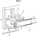
- Figure 5 shows a partial view of the storage container after Fig.1 to Fig.3 with the plug arranged in the connection of the storage container.
- the plug arranged in the connection of the storage container.
- the device according to Figure 5 are the opposite to the device according to Fig.1 to Fig.4 Constant or equivalent parts by the same reference numerals.
Landscapes
- Engineering & Computer Science (AREA)
- Life Sciences & Earth Sciences (AREA)
- Sustainable Development (AREA)
- Sustainable Energy (AREA)
- Chemical & Material Sciences (AREA)
- Combustion & Propulsion (AREA)
- Transportation (AREA)
- Mechanical Engineering (AREA)
- Cooling, Air Intake And Gas Exhaust, And Fuel Tank Arrangements In Propulsion Units (AREA)
- Details Of Rigid Or Semi-Rigid Containers (AREA)
- Closures For Containers (AREA)
Description
- Die Erfindung geht aus von einer Vorrichtung zum Fördern von Kraftstoff nach der Gattung des Hauptanspruchs.
- Es ist schon eine Vorrichtung zum Fördern von Kraftstoff aus einem Kraftstofftank zu einer Brennkraftmaschine bekannt, mit einem Speicherbehälter und einer in einem Anschluss des Speicherbehälteres um eine Drehachse drehbar gelagerten Saugleitung. Eine Saugstrahlpumpe saugt über die Saugleitung Kraftstoff aus einem vom Speicherbehälter entfernten Bereich des Kraftstofftanks an. Das dem Speicherbehälter abgewandte Ende der Saugleitung muß immer an einem Boden des Kraftstofftanks anliegen, damit auch bei sehr geringen Füllständen im Kraftstofftank noch Kraftstoff angesaugt werden kann. Daher weist die Vorrichtung einen Drahtbügel zum Niederhalten der Saugleitung auf, der die Saugleitung in einer vorbestimmten Position hält. Der Drahtbügel ist am Speicherbehälter befestigt und verläuft im wesentlichen parallel zur Saugleitung. Die Saugleitung ist elastisch biegsam ausgebildet und mittels von Befestigungsmitteln am Drahtbügel fixiert. Die Montage der Saugleitung am Drahtbügel ist vergleichsweise aufwendig. Die Kosten für den Drahtbügel sind vergleichsweise hoch.
- Weiterhin ist aus der
DE 198 19 117 C1 eine Vorrichtung zum Fördern von Kraftstoff bekannt, die einen drehbar gelagerten Tragarm aufweist, an dem eine zu einer Saugstrahlpumpe führende Förderleitung vorgesehen ist und der durch ein Fixiermittel gegen eine Innenwand des Kraftstoffbehälters vorgespannt ist. - Den Stand der Technik nach dem Oberbegriff des Anspruchs 1 stellt hier die
DE 198 19 117 dar. - Das erfindungsgemäße Förderagregat mit den kennzeichnenden Merkmalen des Hauptanspruchs hat demgegenüber den Vorteil, dass die Funktion des Drahtbügels in die Saugleitung integriert ist, indem die Saugleitung eine aufgeprägte gebogene Form aufweist und am Speicherbehälter ein die Drehbarkeit der Saugleitung begrenzender Anschlag vorgesehen ist, der derart angeordnet ist, dass die Saugleitung bei dem auf einen Boden aufgesetzten Speicherbehälter gegen den Boden vorgespannt ist. Auf diese Weise werden die Herstellungs- und Montagekosten der Vorrichtung deutlich verringert. Der Drahtbügel entfällt als zusätzliches Teil.
- Durch die in den Unteransprüchen aufgeführten Maßnahmen sind vorteilhafte Weiterbildungen und Verbesserungen der im Hauptanspruch angegebenen Vorrichtung möglich.
- Besonders vorteilhaft ist, wenn der Anschlag rippenförmig ausgebildet ist und mit seiner Längserstreckung in Richtung einer Achse des Speicherbehälteres verläuft, da der Anschlag auf diese Weise besonders stabil ausgebildet ist und mit wenig Kunststoff herstellbar ist.
- Desweiteren vorteilhaft ist, wenn der Anschlag über einen Verbindungssteg mit dem Anschluss verbunden ist, da der Anschlag auf diese Weise noch stabiler ausgeführt ist.
- Gemäß einer vorteilhaften Ausgestaltung ist der Verbindungssteg und/oder der Anschluss mittels Rippen verstärkt.
- Weiterhin vorteilhaft ist, an dem dem Anschluss zugewandten Ende der Saugleitung ein Stecker vorgesehen ist, der mit dem Anschluss verbindbar ist und einen radial bezüglich der Drehachse abstehenden Kragabschnitt aufweist. Durch den Stecker ist die Saugleitung leicht montierbar und austauschbar. Der Kragabschnitt des Steckers wirkt vorteilhafterweise mit dem Anschlag zusammen, so dass die Begrenzung der Drehbarkeit der Saugleitung am Stecker und nicht an der Saugleitung realisiert ist. Dies hat den Vorteil, dass die Saugleitung zuverlässig vorspannbar ist.
- Sehr vorteilhaft ist es, wenn der Anschlag derart ausgebildet ist, dass die Saugleitung oder der Stecker nahe dem Anschlag eine Seitenführung erfahren, da die vorgespannte Saugleitung auf diese Weise nicht seitlich ausweichen kann.
- Vorteilhaft ist, wenn der Anschluss mit einer Unterdruckquelle, vorzugsweise einer Saugstrahlpumpe, strömungsverbunden ist, da auf diese Weise Kraftstoff aus einem vom Speicherbehälter entfernten Bereich angesaugt wird, ohne eine zusätzliche Förderpumpe außerhalb des Speicherbehälteres zu benötigen.
- Ein Ausführungsbeispiel der Erfindung ist in der Zeichnung vereinfacht dargestellt und in der nachfolgenden Beschreibung näher erläutert.
- Fig.1
- zeigt im Schnitt eine vereinfacht dargestellte Vorrichtung mit einem erfindungsgemäßen Speicherbehälter,
- Fig.2
- eine vereinfachte Ansicht der Vorrichtung mit einer Saugleitung,
- Fig.3
- eine dreidimensionale Ansicht des Speicherbehälters nach
Fig.1 mit dem erfindungsgemäßen Anschlag, - Fig.4
- zeigt eine Ansicht des Steckers der Saugleitung, der mit einem Anschluss des Speicherbehälters verbindbar ist und
- Fig.5
- eine Teilansicht des Speicherbehälters nach
Fig.1 undFig.3 mit dem in dem Anschluss befestigten Stecker. -
Fig.1 zeigt im Schnitt eine vereinfacht dargestellte Vorrichtung mit einem erfindungsgemäßen Speicherbehälter. - Die Vorrichtung ist in einem mit Kraftstoff gefüllten Vorratsbehälter 1 angeordnet. Sie weist einen Speicherbehälter 2 und ein Förderaggregat 3 auf, das beispielsweise in dem Speicherbehälter 2 angeordnet ist und aus diesem Kraftstoff ansaugt. Das Förderaggregat 3 fördert den Kraftstoff druckerhöht über eine Druckleitung 4 zu einer Brennkraftmaschine 5. Das Förderaggregat 3 kann aber ausdrücklich auch außerhalb des Speicherbehälters 2 oder des Vorratsbehälters 1 angeordnet sein. Der Speicherbehälter 2 ist an einem Tankboden 7 des Vorratsbehälters 1 angeordnet und dient dazu, ausreichend Kraftstoff um das Förderaggregat 3 herum vorzuhalten, damit dieses auch bei niedrigen Füllständen im Vorratsbehälter 1 und beim Beschleunigen, Bremsen, Kurven- und/oder Bergfahren Kraftstoff ansaugen kann. Der beispielsweise topfförmige Speicherbehälter 2 weist einen Boden 6 auf.
- An der dem Vorratsbehälter 1 zugewandten Mantelfläche des Speicherbehälters 2 ist ein Anschluss 8 für eine Saugleitung 9 vorgesehen, über die Kraftstoff aus einem Bereich des Vorratsbehälters 1 angesaugt wird, der von dem Speicherbehälter 2 entfernt ist. Beispielsweise verläuft die Saugleitung 9 über einen nicht dargestellten Sattel des Vorratsbehälters 1 hinweg in einen abschnittsweise abgetrennten, nicht dargestellten Bereich des Vorratsbehälters 1. Der über die Saugleitung 9 angesaugte Kraftstoff gelangt über eine am Anschluss 8 vorgesehene Öffnung 2.1 im Speicherbehälter 2 in den Speicherbehälter 2. Die Saugleitung 9 ist über den Anschluss 8 mit einer Unterdruckquelle, beispielsweise einer Förderpumpe 10 verbunden, die einen vorbestimmten Unterdruck zum Ansaugen des Kraftstoffes bereitstellt. Als Förderpumpe 10 ist gemäß dem Ausführungsbeispiel eine Saugstrahlpumpe vorgesehen, die beispielsweise über eine von der Druckleitung 4 abzweigende Treibleitung 4.1 angetrieben wird. In der Treibleitung 4.1 ist beispielsweise ein Steuerventil 4.2 vorgesehen, das erst ab einem vorbestimmten Druck öffnet und Kraftstoff zur Saugstrahlpumpe strömen lässt. Es ist jedoch ausdrücklich auch eine elektrisch betriebene Kraftstoffpumpe möglich.
- Die Saugleitung 9 ist am Anschluss 8 um eine Drehachse 11 drehbar gelagert.
-
Fig.2 zeigt eine vereinfachte Ansicht der Vorrichtung mit einer gebogenen und gegen den Tankboden vorgespannten Saugleitung.
Bei der Vorrichtung nachFig.2 sind die gegenüber der Vorrichtung nachFig.1 gleichbleibenden oder gleichwirkenden Teile durch die gleichen Bezugszeichen gekennzeichnet. - Die Saugleitung 9 muss an ihrem dem Anschluss 8 abgewandten Ende an den Tankboden 7 angedrückt sein, damit über die Saugleitung 9 auch bei sehr niedrigem Füllstand in dem Vorratsbehälter 1 Kraftstoff angesaugt werden kann.
- Erfindungsgemäß ist daher vorgesehen, dass die Saugleitung 9 eine aufgeprägte, zumindest abschnittsweise gebogene oder abgewinkelte Form aufweist und am Speicherbehälter 2 ein die Drehbarkeit der Saugleitung 9 begrenzender Anschlag 15 vorgesehen ist, der derart angeordnet ist, dass die Saugleitung 9 bei auf den Tankboden 7 aufgesetztem Speicherbehälter 2 gegen den Tankboden 7 vorgespannt ist. Unter der aufgeprägten Form ist zu verstehen, dass die Saugleitung 9 bei der Herstellung eine vorbestimmte Form mit mindestens einem Biegeradius R erhält und derart steif ausgebildet ist, dass sie diese auch bei Einwirkung einer vorbestimmten Kraft im wesentlichen beibehält. Die Saugleitung 9 ist beispielsweise schlauchförmig ausgebildet.
- Beim Einsetzen des Speicherbehälters 2 in den Vorratsbehälter 1 eilt die Saugleitung 9 gegenüber dem Boden 6 des Speicherbehälters 2 voraus, so dass die Saugleitung 9 vor dem Boden 6 des Speicherbehälters 2 den Tankboden 7 erreicht und sich anschließend um die Drehache 11 unter einer Verkleinerung des spitzen Winkels zwischen der Saugleitung 9 und dem Boden 6 dreht, bis die Saugleitung 9 durch den Anschlag 15 nicht weiter drehbar ist. Wenn die Saugleitung 9 mit ihrem einen Ende ohne Vorspannung am Tankboden 7 anliegt und an ihrem anderen Ende der Anschlag 15 erreicht ist, verbleibt ein vorbestimmter Abstand zwischen dem Boden 6 des Speicherbehälters 2 und dem Tankboden 7, der dazu dient, durch die weitere Bewegung des Speicherbehälters 2 bis an den Tankboden 7 die Saugleitung 9 zwischen dem Anschlag 15 und dem Tankboden 7 vorzuspannen, so dass das dem Tankboden 7 zugewandte Ende der Saugleitung 9 gegen den Tankboden 7 gedrückt ist. Der Anschlag 15 stützt das auf die Saugleitung 9 wirkende Biegemoment ab und bildet auf diese Weise ein Widerlager.
- Der Speicherbehälter 2 ist über Verbindungsmittel 2.2 mit einem Tankflansch 2.3 verbunden, der eine Montageöffnung 1.1 des Vorratsbehälters 1 dicht verschließt.
-
Fig.3 zeigt eine dreidimensionale Ansicht des Speicherbehälters nachFig.1 mit dem erfindungsgemäßen Anschlag.
Bei der Vorrichtung nachFig.3 sind die gegenüber der Vorrichtung nachFig.1 undFig.2 gleichbleibenden oder gleichwirkenden Teile durch die gleichen Bezugszeichen gekennzeichnet. - Der Anschlag 15 ist gemäß dem Ausführungsbeispiel rippenförmig ausgeführt und verläuft mit seiner Längserstreckung in Richtung einer Achse 16 des Speicherbehälters 2. Durch diese Anordnung ist der Anschlag 15 besonders steif ausgeführt. Der Anschlag 15 ist beispielsweise über einen Verbindungssteg 22 mit dem Anschluss 8 fest verbunden, um die Stabilität und Festigkeit des Anschlags 15 zu erhöhen. Der Verbindungssteg 22 verläuft beispielsweise horizontal. Weiterhin kann der Verbindungssteg 22 und der Anschluss 8 mittels von Rippen 23 verstärkt sein. Der Anschlag 15 kann aber auch stegförmig, zylinderförmig, stiftförmig, dornförmig, quaderförmig oder ähnlich ausgeführt sein.
- Der Anschluss 8 ist beispielsweise als Aufnahme oder Stutzen ausgeführt. Der Anschluss 8 ist beispielsweise an seinem dem Speicherbehälter 2 abgewandten Ende umfangsseitig zum Anschlag 15 hin geöffnet. Dadurch ist eine teilringförmige Wandung 8.1 am Ende des Anschlusses 8 gebildet, die einen unteren Anschlag für die Saugleitung 9 bildet, so dass die Saugleitung 9 zwischen dem Anschlag 15 und dem unteren Anschlag drehend bewegbar ist.
- Der Anschlag 15 weist eine vorbestimmte Wandstärke s auf. Die mit der Saugleitung 9 zusammenwirkende Seite 15.1 des Anschlags 15 mit der Wandstärke s ist von der Kontur her beispielsweise der Form der Saugleitung 9 angepasst, so dass die Saugleitung 9 nahe dem Anschlag 15 eine seitliche Führung erhält.
- An dem dem Anschluss 8 zugewandten Ende der Saugleitung 9 ist beispielsweise ein Stecker 12 vorgesehen, der mit dem Anschluss 8 verbindbar und am Anschluss 8 drehbar angeordnet ist. Beispielsweise ist der Stecker 12 mittels einer lösbaren Steck- oder Schnappverbindung am Anschluss 8 befestigt, indem ein Schnapphaken 24 des Steckers 12 in eine Ausnehmung 25 der teilringförmigen Wandung 8.1 einrastet. Die Saugleitung 9 kann aber auch unmittelbar am Anschluss 8 angeschlossen und drehbar sein.
- Der Anschlag 15 kann derart angeordnet sein, dass er bei am Tankboden 7 aufgesetztem Speicherbehälter 2 unmittelbar auf die Saugleitung 9 oder gemäß dem Ausführungsbeispiel mittelbar auf den Kragabschnitt 18 des Steckers 12 vorspannend wirkt.
-
Fig.4 zeigt eine Ansicht des Steckers der Saugleitung. Bei dem Stecker nachFig.4 sind die gegenüber der Vorrichtung nachFig.1 bis Fig.3 gleichbleibenden oder gleichwirkenden Teile durch die gleichen Bezugszeichen gekennzeichnet. - Der Stecker 12 weist einen im Anschluss 8 vorgesehenen Steckerabschnitt 17 und einen vom Steckerabschnitt 17 radial bezüglich der Drehachse 11 abstehenden Kragabschnitt 18 auf. Der Steckerabschnitt 17 und der Kragabschnitt 18 bilden gemäß dem Ausführungsbeispiel einen 90-Grad Rohrbogen, in dem ein Verbindungskanal 19 ausgebildet ist. Die Saugleitung 9 ist mit dem Verbindungskanal 19 strömungsverbunden, beispielsweise indem sie auf einen Stutzen des Kragabschnitts 18 aufgeschoben ist. Der Verbindungskanal 19 mündet über die Öffnung 2.1 in den Speicherbehälter 2. Die Saugleitung 9 könnte aber auch an der Stirnseite des Steckerabschnitts 17 angeschlossen sein und der Kragabschnitt 18 zusammen mit dem Anschlag 15 nur die Funktion des Spannungsaufbaus haben.
In einer Nut 26 des Steckerabschnitts 17 ist ein Dichtelement 27, beispielsweise ein O-Ring, vorgesehen, der die Verbindung zwischen dem Anschluss 8 und dem Stecker 12 abdichtet. -
Fig.5 zeigt eine Teilansicht des Speicherbehälters nachFig.1 bis Fig.3 mit dem im Anschluss des Speicherbehälters angeordneten Stecker.
Bei der Vorrichtung nachFig.5 sind die gegenüber der Vorrichtung nachFig.1 bis Fig.4 gleichbleibenden oder gleichwirkenden Teile durch die gleichen Bezugszeichen gekennzeichnet.
Claims (8)
- Vorrichtung zum Fördern von Kraftstoff mit einem Speicherbehälter (2), einem Kraftstoff aus dem Speicherbehälter (2) ansaugenden Förderaggregat (3), einer um eine Drehachse (11) drehbar gelagerten Leitung (9), die eine aufgeprägte gebogene oder abgewinkelte Form aufweist, und mit einem die Drehbarkeit der Leitung (9) begrenzenden Anschlag (15), und wobei die Leitung (9) eine Saugleitung ist, die über einen am Speicherbehälter (2) vorgesehenen Anschluss (8) mit einer Unterdruckquelle (10) verbunden ist, dadurch gekennzeichnet, das an dem dem Anschluss (8) zugewandten Ende der Saugleitung (9) ein Stecker (12) vorgesehen ist, der mit dem Anschluss (8) verbindbar ist und einen in den Speicherbehälter (2) mündenden Verbindungskanal (19) aufweist, der mit der Saugleitung (9) strömungsverbunden ist, und dass der Anschlag (15) am Speicherbehälter (2) derart angeordnet ist, dass die Saugleitung (9) bei auf einen Boden (7) aufgesetztem Speicherbehälter (2) gegen den Boden (7) vorgespannt ist.
- Vorrichtung nach Anspruch 1, dadurch gekennzeichnet, dass der Anschlag (15) rippenförmig, zylinderförmig oder quaderförmig ausgebildet ist.
- Vorrichtung nach Anspruch 1, dadurch gekennzeichnet, dass der Anschlag (15) über einen Verbindungssteg (22) mit dem Anschluss (8) verbunden ist.
- Vorrichtung nach Anspruch 3, dadurch gekennzeichnet, dass der Verbindungssteg (22) und der Anschluss (8) mittels Rippen (23) verstärkt sind.
- Vorrichtung nach Anspruch 1, dadurch gekennzeichnet, dass der Stecker (12) einen radial bezüglich der Drehachse (11) abstehenden Kragabschnitt (18) aufweist.
- Vorrichtung nach Anspruch 1 oder 5, dadurch gekennzeichnet, dass der Anschlag (15) unmittelbar auf die Saugleitung (9) oder mittelbar auf den Kragabschnitt (18) des Steckers (12) vorspannend wirkt.
- Vorrichtung nach Anspruch 1 oder 5, dadurch gekennzeichnet, dass der Anschlag (15) derart ausgebildet ist, dass die Saugleitung (9) oder der Stecker (12) nahe dem Anschlag (15) eine Seitenführung erfahren.
- Vorrichtung nach Anspruch 1, dadurch gekennzeichnet, dass der Anschluss (8) mit einer Saugstrahlpumpe strömungsverbunden ist.
Applications Claiming Priority (1)
| Application Number | Priority Date | Filing Date | Title |
|---|---|---|---|
| DE200710004565 DE102007004565A1 (de) | 2007-01-30 | 2007-01-30 | Vorrichtung zum Fördern von Kraftstoff |
Publications (2)
| Publication Number | Publication Date |
|---|---|
| EP1953024A1 EP1953024A1 (de) | 2008-08-06 |
| EP1953024B1 true EP1953024B1 (de) | 2016-03-30 |
Family
ID=39183042
Family Applications (1)
| Application Number | Title | Priority Date | Filing Date |
|---|---|---|---|
| EP08100066.3A Ceased EP1953024B1 (de) | 2007-01-30 | 2008-01-03 | Vorrichtung zum Fördern von Kraftstoff |
Country Status (3)
| Country | Link |
|---|---|
| EP (1) | EP1953024B1 (de) |
| CN (1) | CN101235776B (de) |
| DE (1) | DE102007004565A1 (de) |
Families Citing this family (2)
| Publication number | Priority date | Publication date | Assignee | Title |
|---|---|---|---|---|
| DE102013204709A1 (de) * | 2013-02-14 | 2014-08-14 | Robert Bosch Gmbh | Vorrichtung zum Fördern von Kraftstoff |
| EP3750738A1 (de) * | 2019-06-14 | 2020-12-16 | F.A.R.M.A. S.r.l. Fabbrica Accessori Ricambi Moto e Auto | Einlassanordnung für kraftstofftanks von fahrzeugen |
Family Cites Families (8)
| Publication number | Priority date | Publication date | Assignee | Title |
|---|---|---|---|---|
| US5236000A (en) * | 1992-10-05 | 1993-08-17 | Kizer Thomas L | In-tank fuel supply system and method of installation |
| FR2753658B1 (fr) * | 1996-09-26 | 1998-12-11 | Dispositif de puisage de carburant pour reservoir de vehicules automobiles | |
| DE19823573B4 (de) * | 1997-11-12 | 2011-01-27 | Continental Automotive Gmbh | Kraftstoffördereinheit zum Einsatz in Kraftstofftanks |
| DE19816317A1 (de) * | 1998-04-11 | 1999-10-14 | Bosch Gmbh Robert | Kraftstoffördereinrichtung |
| DE19819117C1 (de) * | 1998-04-29 | 1999-11-11 | Mannesmann Vdo Ag | Kraftstoffbehälter |
| DE19900378B4 (de) * | 1999-01-08 | 2005-03-17 | Siemens Ag | Tanksystem |
| KR100534731B1 (ko) * | 2003-09-19 | 2005-12-07 | 기아자동차주식회사 | 자동차용 연료 펌프 어셈블리 |
| HUP0400276A2 (hu) * | 2004-01-27 | 2005-10-28 | Visteon Global Technologies, Inc. | Javított indítási tulajdonságokkal rendelkező sugárszivattyú, valamint ilyennel szerelt üzemanyag-továbbító rendszer |
-
2007
- 2007-01-30 DE DE200710004565 patent/DE102007004565A1/de not_active Withdrawn
-
2008
- 2008-01-03 EP EP08100066.3A patent/EP1953024B1/de not_active Ceased
- 2008-01-30 CN CN 200810008887 patent/CN101235776B/zh not_active Expired - Fee Related
Also Published As
| Publication number | Publication date |
|---|---|
| CN101235776B (zh) | 2013-05-08 |
| DE102007004565A1 (de) | 2008-08-07 |
| CN101235776A (zh) | 2008-08-06 |
| EP1953024A1 (de) | 2008-08-06 |
Similar Documents
| Publication | Publication Date | Title |
|---|---|---|
| EP0694691B1 (de) | Vorrichtung zum Fördern von Kraftstoff aus einem Vorratsbehälter zur Brennkraftmaschine eines Kraftfahrzeugs | |
| DE19618454B4 (de) | Kraftstoffördereinrichtung eines Kraftfahrzeuges | |
| DE19961923A1 (de) | Kraftstofffördermodul für Kraftfahrzeuge | |
| EP0989936B1 (de) | Kraftstofffördereinrichtung | |
| EP2102483B1 (de) | Reservoir für einen kraftstoffbehälter | |
| WO1996035871A1 (de) | Vorrichtung zum versorgen einer brennkraftmaschine mit kraftstoff aus einem vorratsbehälter | |
| WO2001094143A1 (de) | Vorrichtung zum fördern von kraftstoff aus einem vorratstank zu einer brennkraftmaschine eines kraftfahrzeugs | |
| EP0284662A2 (de) | Scheibenwaschanlage für Kraftfahrzeuge | |
| EP2122152A1 (de) | Fördereinheit | |
| EP1527269B1 (de) | Saugstrahlpumpe | |
| EP1953024A1 (de) | Vorrichtung zum Fördern von Kraftstoff | |
| EP2652307B1 (de) | Kraftstoff-fördereinheit | |
| DE102011016733A1 (de) | Kraftstoffpumpenmodul mit Doppelstrahlsystem | |
| DE3022443C2 (de) | Saugrohr für den Schmierölkreislauf einer Brennkraftmaschine | |
| DE10309712A1 (de) | Vorrichtung zum Fördern von Kraftstoff aus einem Vorratsbehälter zu einer Brennkraftmaschine | |
| DE102005061604B4 (de) | Kraftstoffentnahmesystem für ein Zusatzheizgerät, Zusatzheizgerät und Kraftfahrzeug mit einem solchen Kraftstoffentnahmesystem | |
| EP2234833A1 (de) | Vorrichtung zur halterung eines förderaggregates | |
| DE102010039547B4 (de) | Vorrichtung zum Fördern von Kraftstoff aus einem Vorratsbehälter zu einer Brennkraftmaschine | |
| DE102012200590A1 (de) | Vorrichtung zum Fördern von Kraftstoff | |
| DE102012200588A1 (de) | Vorrichtung zum Fördern von Kraftstoff | |
| DE102005014431B3 (de) | Saugstrahlpumpe | |
| WO2013057012A1 (de) | Kraftstoffförder-vorrichtung mit geneigter saugstrahlpumpe | |
| DE102005021322A1 (de) | In einem Kraftstoffbehälter angeordnete Fördereinheit | |
| EP1988323B1 (de) | Zur Montage innerhalb eines Kraftstoffbehälters vorgesehene Kraftstoffpumpe mit einem Adapter | |
| EP1861612B1 (de) | Fördereinheit |
Legal Events
| Date | Code | Title | Description |
|---|---|---|---|
| PUAI | Public reference made under article 153(3) epc to a published international application that has entered the european phase |
Free format text: ORIGINAL CODE: 0009012 |
|
| AK | Designated contracting states |
Kind code of ref document: A1 Designated state(s): AT BE BG CH CY CZ DE DK EE ES FI FR GB GR HR HU IE IS IT LI LT LU LV MC MT NL NO PL PT RO SE SI SK TR |
|
| AX | Request for extension of the european patent |
Extension state: AL BA MK RS |
|
| 17P | Request for examination filed |
Effective date: 20090206 |
|
| AKX | Designation fees paid |
Designated state(s): DE FR IT |
|
| 17Q | First examination report despatched |
Effective date: 20090520 |
|
| GRAP | Despatch of communication of intention to grant a patent |
Free format text: ORIGINAL CODE: EPIDOSNIGR1 |
|
| INTG | Intention to grant announced |
Effective date: 20151001 |
|
| GRAS | Grant fee paid |
Free format text: ORIGINAL CODE: EPIDOSNIGR3 |
|
| GRAA | (expected) grant |
Free format text: ORIGINAL CODE: 0009210 |
|
| AK | Designated contracting states |
Kind code of ref document: B1 Designated state(s): DE FR IT |
|
| REG | Reference to a national code |
Ref country code: DE Ref legal event code: R096 Ref document number: 502008014006 Country of ref document: DE |
|
| REG | Reference to a national code |
Ref country code: DE Ref legal event code: R097 Ref document number: 502008014006 Country of ref document: DE |
|
| REG | Reference to a national code |
Ref country code: FR Ref legal event code: PLFP Year of fee payment: 10 |
|
| PLBE | No opposition filed within time limit |
Free format text: ORIGINAL CODE: 0009261 |
|
| STAA | Information on the status of an ep patent application or granted ep patent |
Free format text: STATUS: NO OPPOSITION FILED WITHIN TIME LIMIT |
|
| 26N | No opposition filed |
Effective date: 20170103 |
|
| REG | Reference to a national code |
Ref country code: FR Ref legal event code: PLFP Year of fee payment: 11 |
|
| PGFP | Annual fee paid to national office [announced via postgrant information from national office to epo] |
Ref country code: FR Payment date: 20180124 Year of fee payment: 11 Ref country code: IT Payment date: 20180126 Year of fee payment: 11 |
|
| PG25 | Lapsed in a contracting state [announced via postgrant information from national office to epo] |
Ref country code: FR Free format text: LAPSE BECAUSE OF NON-PAYMENT OF DUE FEES Effective date: 20190131 |
|
| PG25 | Lapsed in a contracting state [announced via postgrant information from national office to epo] |
Ref country code: IT Free format text: LAPSE BECAUSE OF NON-PAYMENT OF DUE FEES Effective date: 20190103 |
|
| PGFP | Annual fee paid to national office [announced via postgrant information from national office to epo] |
Ref country code: DE Payment date: 20240322 Year of fee payment: 17 |
|
| REG | Reference to a national code |
Ref country code: DE Ref legal event code: R119 Ref document number: 502008014006 Country of ref document: DE |
|
| PG25 | Lapsed in a contracting state [announced via postgrant information from national office to epo] |
Ref country code: DE Free format text: LAPSE BECAUSE OF NON-PAYMENT OF DUE FEES Effective date: 20250801 |