EP1952115B1 - Linsenuntersuchungssystem mit phasenkontrastabbildung - Google Patents
Linsenuntersuchungssystem mit phasenkontrastabbildung Download PDFInfo
- Publication number
- EP1952115B1 EP1952115B1 EP06819659A EP06819659A EP1952115B1 EP 1952115 B1 EP1952115 B1 EP 1952115B1 EP 06819659 A EP06819659 A EP 06819659A EP 06819659 A EP06819659 A EP 06819659A EP 1952115 B1 EP1952115 B1 EP 1952115B1
- Authority
- EP
- European Patent Office
- Prior art keywords
- imaging unit
- phase contrast
- lens
- field imaging
- image
- Prior art date
- Legal status (The legal status is an assumption and is not a legal conclusion. Google has not performed a legal analysis and makes no representation as to the accuracy of the status listed.)
- Active
Links
Images


Classifications
-
- G—PHYSICS
- G01—MEASURING; TESTING
- G01M—TESTING STATIC OR DYNAMIC BALANCE OF MACHINES OR STRUCTURES; TESTING OF STRUCTURES OR APPARATUS, NOT OTHERWISE PROVIDED FOR
- G01M11/00—Testing of optical apparatus; Testing structures by optical methods not otherwise provided for
- G01M11/02—Testing optical properties
Definitions
- the present invention relates to an inspection system for the automatic inspection of ophthalmic lenses, preferably in an automated lens manufacturing line.
- the inspection system provides a phase contrast imaging unit and an inspection method using said phase contrast imaging unit designed to recognize defective lenses with an improved degree of reliability but that does not falsely sort out perfect lenses.
- these contact lenses are formed using reusable mould halves, the female and the male, which are normally formed from glass or quartz.
- these mould halves define a hollow cavity, which corresponds to the subsequent contact lens shape.
- a polymer solution is dosed into the female mould half.
- UV light is radiated over a mould half, which leads to crosslinking of the lens material in the lens cavity.
- the lens is removed from the mould half, for example with suction grips or mechanical grippers, and placed in the package.
- contact lenses are intended for use in the eye, great care is taken to make sure that lenses meet strict quality control standards.
- automatic inspection of the contact lenses using industrial image processing methods may be implemented.
- the known methods for inspection of ophthalmic lenses are based on bright-field and/or dark-field imaging.
- WO-A-2005/054807 discloses a method for the automatic inspection of contact lenses, in particular tinted contact lenses, in an automatic lens manufacturing process, the method comprising the use of a dark-field inspection unit with the preferred dark-field inspection method being the so-called Schlieren method.
- EP-A-1248092 further discloses the combination of a dark-field inspection unit and a bright-field inspection unit, preferably the combination of the so-called Schlieren method and the transmitted light method.
- WO-A-2004/057297 discloses a method for optically inspecting and detecting defects in an object using two different light sources, in particular using a dark-field setup as the first detection method and a bright-field setup as the second detection method.
- WO-A-03/073060 discloses the dual inspection of ophthalmic lenses using at least two different machine vision inspection techniques in the manufacturing process for said ophthalmic lenses, the preferred at least two inspection techniques being bright field and dark field inspection techniques; others being absorptive inspection, structure light inspection, fluorescence inspection and spectral masking.
- WO-A-99/32869 discloses a system for inspecting contact lenses which utilizes a light source and an electronic camera for obtaining images of the lens, as well as a series of masks, including a bright-field mask, a dark-field mask and a transition mask which is constituted by fine stripes, such that the light interacts in a constructive and destructive manner at different distances from the mask. The images are taken subsequently using one mask at a time.
- EP-A-0686942 discloses a lens inspection system and method using two optimized bright-field illumination zones, i.e. using light at two different grey levels, one grey level for the centre zone and one grey level for the peripheral zone.
- phase contrast another conceivable inspection method
- US-A-5751475 discloses a phase contrast microscope including a phase plate, which is formed by a liquid crystal and a pair of transparent ring-shaped electrodes arranged on both sides of the liquid crystal.
- a phase difference introduced by the phase plate is set to +/- ⁇ /2 to obtain a dark contrast image and a bright contrast image. From their difference a phase contrast image having high contrast and resolution is derived.
- US-A-5066120 discloses a device for phase detection testing of an ophthalmic lens, comprising along an optical axis, a light source, a holding station which receives the ophthalmic lens, an array, a receiving device which receives the image observable downstream of the array, and a data processing device which exploits this image by phase detection.
- a suitable inspection method and apparatus should carry out an exhaustive examination of the ophthalmic lenses for accuracy of size, surface defects, tears, peripheral ruptures and inclusions such as bubbles and foreign bodies, as well as small defects at the edges of an ophthalmic lens.
- phase contrast technique employs an optical mechanism to translate minute variations in phase into corresponding changes in amplitude, which can be visualized as differences in image contrast. Further, it is known, that phase contrast imaging can be employed as a technique to render a contrast-enhancing effect in imaging transparent specimen.
- phase contrast imaging and bright-field imaging simultaneously provides an even more accurate inspection system.
- phase contrast imaging method for inspecting an ophthalmic lens is based on the transformation of refractive index differences into intensity differences whereas bright-field imaging is based on absorption differences. According to the invention both imaging methods are combined and applied simultaneously.
- the basis of the transformation for the phase contrast imaging Is the interference property.
- the result of interference of two waves of light depends upon their phase relationship. There are two extremes. If the two waves meet in exactly the same phase they will interfere in a completely constructive manner, i.e., they will be additive and the intensity of light that results will be the sum of the intensities of the interfering waves. If the two interfering waves are one-half wavelength out of phase, the interference will be totally destructive and the two waves will cancel out. Any other phase relationship will produce intermediate intensity.
- the phase contrast imaging unit of the present invention accomplishes two tasks that the bright-field observation alone does not: it separates the background light from the light scattered by the specimen (i.e. the contact lens), and it causes the scattered and unscattered waves to be approximately one-quarter or one-half a wavelength out of phase with each other so that they can destructively interfere and cause changes in intensity.
- the phase contrast imaging unit has a phase plate between the specimen and the detector. Any background light which is not deviated or scattered by the specimen passes though the phase plate. When the deviated and undeviated beams of light are recombined further along the light path, the differences in the phase of the deviated and undeviated light beams become additive or subtractive.
- the resulting wave is the sum of the two waves which have their crests and troughs opposite each other.
- the resulting wave is up to four times darker than the background. Therefore the specimen appears darker than the background and features on the specimen will be either lighter or darker than the surrounding field.
- the resulting image when viewed by a user, or analyzed by a computer program, makes tears and other small defects visible.
- the invention includes a phase contrast imaging method and apparatus. Therefore, the phase of the light is not analyzed as such (as for example in US 5066120 ), but the difference of intensity due to in-phase or phase-shifted interference is captured as an image. Only then, said image is used for detecting accuracy of size, surface defects, tears, peripheral ruptures and inclusions such as bubbles and foreign bodies, as well as small defects at the edges.
- FIG. 1 An inspection device according to one embodiment of the invention is illustrated in Figure 1 and preferably consists of a phase contrast inspection unit 1 and bright-field inspection unit 2.
- the contact lens 3 which is preferably a soft contact lens, is held in a container 4.
- phase plate 9 is mounted in or near the objective rear focal plane (see enlarged part of Fig. 1 ) in order to selectively alter the phase and amplitude of the surround (or undeviated) light passing through the specimen.
- phase plate typically is made of a phase retarding material, such as a dielectric thin film on a glass plate 10.
- phase plates are produced by vacuum deposition of thin dielectric and metallic films onto a glass plate or directly onto a lens surface.
- the role of the dielectric thin film is to shift the phase of light, while the metallic film attenuates undiffracted light intensity.
- a "positive" phase plate produces dark contrast and contains a partially absorbing film designed to reduce the amplitude of the surround wavefront.
- this plate contains phase retarding material designed to shift (retard) the phase of the diffracted light by 90 degrees.
- a "negative" phase plate also contains both phase retarding and partially absorbing materials. However, in this case, both materials are sandwiched within the phase plate so that the undiffracted surround wavefront is the only species affected (attenuated and retarded in phase by 90 degrees).
- phase plates that alter the phase of surround light relative to diffracted light by 90 degrees are termed quarter wavelength plates because of their effect on the optical path difference.
- the phase plate width and diameter both decrease.
- the thin phase plate contains a ring etched into the glass that has reduced thickness in order to differentially advance the phase of the surround wave by a quarter-wavelength.
- the ring is further coated with a partially absorbing metallic film to reduce the surround light amplitude by 60 to 90 percent. Because the rear focal plane usually resides near an internal lens element, some phase contrast objectives are produced by actually etching into the surface of a lens.
- the contact lens 3 is preferably at least temporarily housed in a container 4 that is transparent at least at the bottom to allow the illumination beam coming from the light source 5 to be transmitted trough the contact lens 3.
- the container 4 may be open at the top or closed by means of a transparent window.
- the container 4 is preferably at least partially filled with a fluid solution, such as, for example, water or saline solution or a similar test liquid.
- a fluid solution such as, for example, water or saline solution or a similar test liquid.
- the shape of the container is such that, when a contact lens is placed in the container the container tends to centre the lens automatically therein at its bottom.
- the container may stand alone on the transport subsystem or may be part of a lens carrier provided to hold a multitude of containers.
- the light source 5 is used to illuminate the contact lens 3 and may be any suitable kind of monochromatic light source generating either a continuous illumination beam or a serious of flashes or pulses.
- the inspection system preferably further includes a synchronization or coordination mechanism between the transport subsystem and the light source which takes care that the light source is activated exactly when the contact lens is in the inspection position.
- preferred light sources are light emitting diodes (LEDs) or short arc-xenon flash lamps.
- Other types of light sources, such as halogen lamps may be used, in which case a filter may be used to create monochromatic light.
- the light emanating from the light source 5 is then collimated by a suitable lens 6.
- a concave mirror (not shown) may be used.
- the light reflected by the light source 5 and the concave mirror is then focused onto an input diaphragm (not shown), in a preferred embodiment by a heat filter and a biconvex lens (not shown).
- the diaphragm lies in the focus point of a further lens, so that the light emanating from the light source 5 is collimated and parallel light is present in the examining zone.
- an interference filter (not shown) to be additionally used behind the lens 6, in order to substantially increase the length of coherence of the light emanating from the light source 5.
- the illumination beam transmitted through the contact lens 3 is incident on an imaging convex lens 7.
- a beam splitter 8 e.g. a beam-dividing cube.
- One beam is that of the phase contrast optics and the other beam is given in transmitted light (i.e. directed to the bright field optics).
- the beam splitter may be used in the same way to direct one beam to the phase contrast optics and the other beam to a dark field optics.
- the beam splitter may be used to direct one beam to the phase contrast optics and the other beam to a bright and dark field optics.
- the imaging units are each completed by a lens 14 and 16 and a CCD camera 15 and 17.
- achromatic lenses are preferably used, in order to avoid aberrations. Observation is preferably carried out under a small angle.
- a dark-field inspection unit may be used in combination with a bright-field inspection unit and a phase contrast imaging unit which more easily recognizes linear surface defects outside the iris print.
- This dark-field method characterized by the fact that a beam stop is positioned between the contact lens and the camera was introduced by A. Toepler to examine lenses and it is known in literature as Schlieren method.
- Schlieren systems are especially effective in detecting cosmetic defects such as surface defects, tears, ruptures and inclusions such as bubbles and foreign bodies.
- the phase retarding plate 9 may be complemented by a beam stop 13 in the filter plane 12 (both not shown in Figure 1 ).
- Beam stop 13 should advantageously be of larger diameter than the input diaphragm (not shown in Figure 1 ), so that the illuminating part of the beam is fully scattered by the imaging properties of the contact lens 3 despite deviations in the illuminating beam.
- the beam stop 13 should not be too large, because a disadvantageous number of low frequency parts may be filtered out.
- the deviation of the scattered beam is small as compared to the direction of the beam.
- the size of the beam stop 13 is advantageously 2-3 mm.
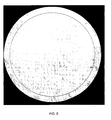
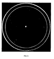
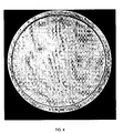
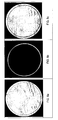
- Figures 2 to 4 show a bright-field ( Fig. 2 ), a dark-field ( Fig. 3 ) and a phase contrast image ( Fig. 4 ) of a contact lens in high resolution.
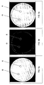
- Figures 5 to 8 the images of lens specimen obtained with bright-field, dark-field and phase contrast imaging are compared.
- Fig. 5 features a lens with a bubble in the lens material (X) as well as with an adhering air bubble on the surface of the lens (O).
- the latter (O) is not a lens defect
- the bubble in the lens material (X) is a lens defect which has to be identified by the system and method of the present invention to reject the lens as defective.
- Fig. 5a is the bright-field image
- Fig. 5b is the dark-field image
- Fig. 5c is the phase contrast image of the same lens. Only the phase contrast image allows to distinguish X from O, as X shows a bright halo around the defect, whereas 0 only appears as a black spot.
- the first bright-field image can be used to identify the area for potential defects, which then is either confirmed or disapproved by the subsequent or simultaneous second phase contrast image ( Fig. 5c ).
- Fig. 6 features a lens with two bubbles in the lens material (X), both appearing with a bright halo in the phase contrast image. One of them is poorly visible in Fig. 6a , whereas it is clearly visible in Fig. 6b .
- the first dark-field image ( Fig. 6b ) can be used to identify the area for potential defects, which then is either confirmed or disapproved by the subsequent or simultaneous second phase contrast image ( Fig. 6c ).
- Fig. 7 shows a comparison of a bright-field and a phase contrast image taken simultaneously of the same toric lens.
- the bubble in the lens material (X) appears undistinguishable from an adhering air bubble on the surface of the lens (O) as in the previous images.
- the bright halo reveals the true nature of the defect to reject the lens.
- phase contrast image ( Fig. 7c ) alone or the combination with the bright-field image (Fig. 7a) would allow to reliably reject a lens (and only a lens) with true defects.
- Fig. 8 shows three images of a toric lens, i.e. a lens where the orientation on the eye is essential for the effective vision correction. Neither the bright-field ( Fig. 8a ), nor the dark-field ( Fig. 8b ) image allow to capture the orientation of the lens in the package. However, the phase contrast image ( Fig. 8c ) clearly reveals the underlying optical design and the respective orientation of the lens.
- the present invention is preferably used on a manufacturing line.
- the specimen contact lens
- the lens inspection position wherein one lens at the time is inspected.
- the lens is continuously moving through the inspection system, however the lens may also be in a stationary position during the inspection.
- this method is particularly effective to inspect tinted contact lenses. Cosmetic defects which may be hidden by the iris print become clearly detectable.
- the image is automatically processed by a computer which decides whether to reject the lens or process it further according to preset selection criteria by any known method in the art.
- the methods described above are suitable to inspect any kind of ophthalmic lenses, in particular contact lenses.
- the contact lens is a soft contact lens for example a conventional hydrogel lens which comprises for example a poly-HEMA homo or copolymer, a PVA homo or copolymer, or a crosslinked polyethylenglycol or a polysiloxane hydrogel.
- the contact lens is a tinted contact lens.
Landscapes
- Chemical & Material Sciences (AREA)
- Analytical Chemistry (AREA)
- Physics & Mathematics (AREA)
- General Physics & Mathematics (AREA)
- Testing Of Optical Devices Or Fibers (AREA)
- Investigating Materials By The Use Of Optical Means Adapted For Particular Applications (AREA)
Claims (8)
- Verfahren zur Inspektion einer ophthalmischen Linse (3) umfassend Verwenden einer Hellfeld-Abbildungseinheit (2) oder einer Dunkelfeld-Abbildungseinheit, gekennzeichnet durch gleichzeitiges Einsetzen einer Phasenkontrast-Abbildungseinheit (1) und der Hellfeld-Abbildungseinheit (2) oder der Dunkelfeld-Abbildungseinheit, und durch zuerst Verwenden eines Hellfeldbildes der Hellfeld-Abbildungseinheit (2) oder eines Dunkelfeldbildes der Dunkelfeld-Abbildungseinheit zum Identifizieren eines Bereichs der ophthalmischen Linse (3) mit möglichen Fehlern, der dann durch ein Phasenkontrastbild der Phasenkontrast-Einheit (1) entweder bestätigt oder verworfen wird.
- Verfahren gemäss Anspruch 1, ferner umfassend gleichzeitiges Einsetzen einer Hellfeld-Abbildungseinheit und einer Dunkelfeld-Abbildungseinheit.
- Verfahren gemäss Anspruch 1, bei welchem ein Strahlteiler (8) dazu verwendet wird Licht zur Phasenkontrast-Abbildungseinheit (1) und zur Hellfeld-Abbildungseinheit (2) zu lenken.
- Verfahren gemäss Anspruch 2, bei welchem ein Strahlteiler (8) dazu verwendet wird Licht zur Phasenkontrast-Abbildungseinheit (1) und zur Dunkelfeld-Abbildungseinheit zu lenken.
- Verfahren gemäss Anspruch 2, bei welchem ein Strahlteiler (8) dazu verwendet wird Licht zur Phasenkontrast-Abbildungseinheit (1), zur Hellfeld-Abbildungseinheit (2) und zur Dunkelfeld-Abbildungseinheit zu lenken.
- Verfahren gemäss einem der vorangehenden Ansprüche, wobei das Verfahren ein automatisches Inspektionsverfahren in einer automatisierten Linsenfertigungsstrasse ist.
- Vorrichtung zur Untersuchung einer ophthalmischen Linse (3) unter Verwendung eines Verfahrens gemäss Anspruch 1, wobei die Vorrichtung in optischer Verbindung umfasst:eine Lichtquelle (5);ein oder mehrere optische Elemente (6; 7);einen Behälter (4) zum Halten einer Probenkontaktlinse (3);ein oder mehrere Kamerasensoren (15; 17);einen Strahlteiler (8), undeine Hellfeld-Abbildungseinheit (2) oder eine Dunkelfeld-Abbildungseinheit,dadurch gekennzeichnet, dass die Vorrichtung ferner eine Phasenkontrast-Abbildungseinheit (1) umfasst, wobei die Hellfeld-Abbildungseinheit (2) oder die Dunkelfeld-Abbildungseinheit und die Phasenkontrast-Abbildungseinheit (1) so angepasst sind, dass sie gleichzeitig eingesetzt werden, und wobei ein Hellfeldbild der Hellfeld-Abbildungseinheit (2) oder ein Dunkelfeldbild der Dunkelfeld-Abbildungseinheit angepasst sind zuerst zur Identifizierung eines Bereichs der ophthalmischen Linse (3) mit möglichen Fehlen verwendet zu werden, der dann mittels eines Phasenkontrastbildes der Phasenkontrasteinheit (1) bestätigt oder verworfen wird.
- Vorrichtung gemäss Anspruch 7, ferner umfassend eine Hellfeld-Abbildungseinheit und eine Dunkelfeld-Abbildungseinheit, die gleichzeitig mit der Phasenkontrast-Abbildungseinheit (1) verwendet werden.
Priority Applications (1)
| Application Number | Priority Date | Filing Date | Title |
|---|---|---|---|
| EP06819659A EP1952115B1 (de) | 2005-11-24 | 2006-11-22 | Linsenuntersuchungssystem mit phasenkontrastabbildung |
Applications Claiming Priority (3)
| Application Number | Priority Date | Filing Date | Title |
|---|---|---|---|
| EP05025641 | 2005-11-24 | ||
| EP06819659A EP1952115B1 (de) | 2005-11-24 | 2006-11-22 | Linsenuntersuchungssystem mit phasenkontrastabbildung |
| PCT/EP2006/068744 WO2007060173A1 (en) | 2005-11-24 | 2006-11-22 | Lens inspection system using phase contrast imaging |
Publications (2)
| Publication Number | Publication Date |
|---|---|
| EP1952115A1 EP1952115A1 (de) | 2008-08-06 |
| EP1952115B1 true EP1952115B1 (de) | 2011-12-28 |
Family
ID=36118315
Family Applications (1)
| Application Number | Title | Priority Date | Filing Date |
|---|---|---|---|
| EP06819659A Active EP1952115B1 (de) | 2005-11-24 | 2006-11-22 | Linsenuntersuchungssystem mit phasenkontrastabbildung |
Country Status (6)
| Country | Link |
|---|---|
| US (2) | US7663742B2 (de) |
| EP (1) | EP1952115B1 (de) |
| CN (1) | CN101313205B (de) |
| AT (1) | ATE539338T1 (de) |
| MY (1) | MY149023A (de) |
| WO (1) | WO2007060173A1 (de) |
Families Citing this family (22)
| Publication number | Priority date | Publication date | Assignee | Title |
|---|---|---|---|---|
| WO2009006361A1 (en) * | 2007-06-29 | 2009-01-08 | Johnson & Johnson Vision Care, Inc. | Method of detecting the orientation of an ophthalmic lens in its package |
| US8035809B2 (en) * | 2007-12-21 | 2011-10-11 | Bausch & Lomb Incorporated | Bubble removal system |
| SG173233A1 (en) * | 2010-01-28 | 2011-08-29 | Visionxtreme Pte Ltd | Inspection of defects in a contact lens |
| CN101846812A (zh) * | 2010-04-29 | 2010-09-29 | 中国科学技术大学 | 纹影准单色光源装置 |
| US9253448B1 (en) | 2011-12-28 | 2016-02-02 | Cognex Corporation | System and method for determination of contact lens orientation |
| US8929239B2 (en) * | 2012-07-02 | 2015-01-06 | Apple Inc. | Modulation and coding scheme (MCS) recovery based on CQI offset |
| SG11201603018PA (en) * | 2014-05-15 | 2016-05-30 | Emage Vision Pte Ltd | System and method for inspecting opthalmic lenses |
| CN107110739B (zh) | 2014-08-15 | 2019-08-30 | 齐戈股份有限公司 | 透镜和透镜模具的光学评估 |
| SG10201509497VA (en) * | 2015-11-18 | 2017-06-29 | Emage Vision Pte Ltd | Contact lens defect inspection using uv illumination |
| WO2018224852A2 (en) * | 2017-06-09 | 2018-12-13 | 77 Elektronika Műszeripari Kft. | Combined bright-field and phase-contrast microscopy system and image processing apparatus equipped therewith |
| EP3672792B1 (de) | 2017-08-24 | 2023-07-26 | Alcon Inc. | Modulare fertigungsstrasse zur herstellung von brillengläsern |
| MY203198A (en) | 2017-08-24 | 2024-06-13 | Alcon Inc | Manufacturing module for the manufacture of ophthalmic lenses |
| EP3672790B1 (de) | 2017-08-24 | 2024-10-02 | Alcon Inc. | Produktionslinie zur herstellung von brillengläsern |
| EP3474003A1 (de) * | 2017-10-20 | 2019-04-24 | Essilor International | Verfahren zur bewertung kosmetischer fehler einer optischen vorrichtung |
| WO2019155034A1 (en) | 2018-02-08 | 2019-08-15 | Amo Groningen B.V. | Multi-wavelength wavefront system and method for measuring diffractive lenses |
| US10876924B2 (en) * | 2018-02-08 | 2020-12-29 | Amo Groningen B.V. | Wavefront based characterization of lens surfaces based on reflections |
| MY206070A (en) * | 2018-08-13 | 2024-11-27 | Alcon Inc | Method and apparatus for optically inspecting a mold for manufacturing ophthalmic lenses for possible mold defects |
| CN110579474B (zh) * | 2019-09-24 | 2024-10-18 | 中国科学院力学研究所 | 一种同时观测晶体形貌及测量晶体周围浓度场的装置 |
| CN113984790B (zh) * | 2021-09-28 | 2024-08-30 | 歌尔光学科技有限公司 | 镜片质量检测方法及装置 |
| WO2023111897A1 (en) * | 2021-12-16 | 2023-06-22 | Alcon Inc. | Method and system for inspecting an ophthalmic lens in an automated lens manufacturing process |
| JP2023130330A (ja) * | 2022-03-07 | 2023-09-20 | イメージ エーアイ プライベート リミテッド | 乾燥眼用レンズについてir波長を使用して欠陥を検出するためのシステムおよび方法 |
| EP4633924A2 (de) * | 2022-12-15 | 2025-10-22 | Seurat Technologies, Inc. | Pulverbettmessung zur generativen fertigung |
Family Cites Families (19)
| Publication number | Priority date | Publication date | Assignee | Title |
|---|---|---|---|---|
| GB8702130D0 (en) * | 1987-01-30 | 1987-03-04 | Sira Ltd | Surface inspection |
| FR2647912B1 (fr) * | 1989-06-05 | 1991-09-13 | Essilor Int | Dispositif optique a reseau pour le controle, en transmission, par detection de phase, d'un quelconque systeme optique, en particulier d'une lentille ophtalmique |
| IL96483A (en) * | 1990-11-27 | 1995-07-31 | Orbotech Ltd | Optical inspection method and apparatus |
| IL107603A (en) * | 1992-12-21 | 1997-01-10 | Johnson & Johnson Vision Prod | Ophthalmic lens inspection method and apparatus |
| US5751475A (en) * | 1993-12-17 | 1998-05-12 | Olympus Optical Co., Ltd. | Phase contrast microscope |
| JP3734512B2 (ja) * | 1993-12-27 | 2006-01-11 | 株式会社メニコン | コンタクトレンズ外観検査方法および外観検査装置 |
| US5500732A (en) | 1994-06-10 | 1996-03-19 | Johnson & Johnson Vision Products, Inc. | Lens inspection system and method |
| US6047082A (en) * | 1997-11-14 | 2000-04-04 | Wesley Jessen Corporation | Automatic lens inspection system |
| US6201600B1 (en) | 1997-12-19 | 2001-03-13 | Northrop Grumman Corporation | Method and apparatus for the automatic inspection of optically transmissive objects having a lens portion |
| US6765661B2 (en) * | 2001-03-09 | 2004-07-20 | Novartis Ag | Lens inspection |
| EP1248092B1 (de) * | 2001-03-09 | 2010-09-15 | Novartis AG | Linsenprüfung |
| US6914723B2 (en) * | 2001-11-09 | 2005-07-05 | Xradia, Inc. | Reflective lithography mask inspection tool based on achromatic Fresnel optics |
| CN1358996A (zh) * | 2002-01-29 | 2002-07-17 | 清华大学 | 用透射式微分干涉相衬显微镜测量表面形貌的方法和装置 |
| DE60317492T2 (de) | 2002-02-21 | 2008-10-02 | Johnson & Johnson Vision Care, Inc., Jacksonville | Doppel-inspektion von ophthalmischen linsen |
| AU2003287923A1 (en) | 2002-12-19 | 2004-07-14 | Lk A/S | Method and apparatus for automatic optical inspection |
| US20070121109A1 (en) | 2003-12-04 | 2007-05-31 | Roger Biel | Lens inspection |
| US7084970B2 (en) * | 2004-05-14 | 2006-08-01 | Photon Dynamics, Inc. | Inspection of TFT LCD panels using on-demand automated optical inspection sub-system |
| US7355689B2 (en) * | 2005-01-31 | 2008-04-08 | Applied Materials, Inc. | Automatic optical inspection using multiple objectives |
| ATE554377T1 (de) * | 2005-10-13 | 2012-05-15 | Novartis Ag | Küvette zur optischen untersuchung von freischwimmenden augenoptischen linsen |
-
2006
- 2006-11-21 US US11/602,735 patent/US7663742B2/en active Active
- 2006-11-22 MY MYPI20081597A patent/MY149023A/en unknown
- 2006-11-22 EP EP06819659A patent/EP1952115B1/de active Active
- 2006-11-22 AT AT06819659T patent/ATE539338T1/de active
- 2006-11-22 CN CN2006800435914A patent/CN101313205B/zh active Active
- 2006-11-22 WO PCT/EP2006/068744 patent/WO2007060173A1/en not_active Ceased
-
2010
- 2010-01-07 US US12/683,873 patent/US7855782B2/en active Active
Also Published As
| Publication number | Publication date |
|---|---|
| US7663742B2 (en) | 2010-02-16 |
| ATE539338T1 (de) | 2012-01-15 |
| WO2007060173A1 (en) | 2007-05-31 |
| CN101313205A (zh) | 2008-11-26 |
| US20070139640A1 (en) | 2007-06-21 |
| EP1952115A1 (de) | 2008-08-06 |
| MY149023A (en) | 2013-06-28 |
| US20100157289A1 (en) | 2010-06-24 |
| US7855782B2 (en) | 2010-12-21 |
| CN101313205B (zh) | 2011-08-31 |
Similar Documents
| Publication | Publication Date | Title |
|---|---|---|
| US7855782B2 (en) | Lens inspection system using phase contrast imaging | |
| KR102011209B1 (ko) | 투명 기판이 제공되는 박막을 위한 측정 장치 및 측정 방법 | |
| US6765661B2 (en) | Lens inspection | |
| KR100202215B1 (ko) | 광학부품 특히 눈을 위한 광학부품의 검사방법 및 장치와 청정하고 투명한 검사 물체의 조명장치 | |
| KR100293126B1 (ko) | 검사장치 | |
| CN104662402B (zh) | 用于眼透镜的屈光力的自动化线内确定的方法 | |
| TW201602566A (zh) | 用於檢查眼用透鏡的系統與方法 | |
| EP1248092B1 (de) | Linsenprüfung | |
| CN206710068U (zh) | 大数值孔径浸油镜头波像差检测装置 | |
| CN117969527A (zh) | 光学检测设备 | |
| JP2024046758A (ja) | メガネ・レンズを湿式で成形欠陥を検査するためのシステムおよび方法 | |
| US20070121109A1 (en) | Lens inspection | |
| TWI872962B (zh) | 用於檢驗物件之方法及檢驗系統 | |
| JPS6168543A (ja) | 検体における欠陥の光学的検査方法及びその装置 | |
| JP4136911B2 (ja) | 赤外顕微鏡及びその測定位置確定方法 | |
| JP2014025884A (ja) | 外観検査方法及び外観検査装置 | |
| KR20090014459A (ko) | 미세패턴 박막두께 측정장치 | |
| JP2004309137A (ja) | 石英ガラス材内部の欠陥検査方法および欠陥検査装置 | |
| KR20090018269A (ko) | 화상 형성 장치 및 이를 포함하는 레이저 처리장치, 그리고화상 형성 방법 | |
| JPH09178452A (ja) | 表面観察光学系 | |
| CN118604012A (zh) | 一种用于检测透明玻璃缺陷的检测装置及检测方法 | |
| CN116148261A (zh) | 一种用于光学元件缺陷检测的检测装置和方法 | |
| JPH075401A (ja) | レンズ検査装置及びその検査方法 | |
| TW202544449A (zh) | 檢查裝置以及檢查方法 | |
| JP2588473Y2 (ja) | 表面微小欠陥・付着物の立体像観察用光学顕微鏡 |
Legal Events
| Date | Code | Title | Description |
|---|---|---|---|
| PUAI | Public reference made under article 153(3) epc to a published international application that has entered the european phase |
Free format text: ORIGINAL CODE: 0009012 |
|
| 17P | Request for examination filed |
Effective date: 20080508 |
|
| AK | Designated contracting states |
Kind code of ref document: A1 Designated state(s): AT BE BG CH CY CZ DE DK EE ES FI FR GB GR HU IE IS IT LI LT LU LV MC NL PL PT RO SE SI SK TR |
|
| RAP1 | Party data changed (applicant data changed or rights of an application transferred) |
Owner name: NOVARTIS AG |
|
| 17Q | First examination report despatched |
Effective date: 20080912 |
|
| GRAP | Despatch of communication of intention to grant a patent |
Free format text: ORIGINAL CODE: EPIDOSNIGR1 |
|
| GRAS | Grant fee paid |
Free format text: ORIGINAL CODE: EPIDOSNIGR3 |
|
| GRAA | (expected) grant |
Free format text: ORIGINAL CODE: 0009210 |
|
| AK | Designated contracting states |
Kind code of ref document: B1 Designated state(s): AT BE BG CH CY CZ DE DK EE ES FI FR GB GR HU IE IS IT LI LT LU LV MC NL PL PT RO SE SI SK TR |
|
| DAX | Request for extension of the european patent (deleted) | ||
| REG | Reference to a national code |
Ref country code: GB Ref legal event code: FG4D |
|
| REG | Reference to a national code |
Ref country code: CH Ref legal event code: EP |
|
| REG | Reference to a national code |
Ref country code: AT Ref legal event code: REF Ref document number: 539338 Country of ref document: AT Kind code of ref document: T Effective date: 20120115 |
|
| REG | Reference to a national code |
Ref country code: IE Ref legal event code: FG4D |
|
| REG | Reference to a national code |
Ref country code: DE Ref legal event code: R096 Ref document number: 602006026756 Country of ref document: DE Effective date: 20120308 |
|
| REG | Reference to a national code |
Ref country code: NL Ref legal event code: VDEP Effective date: 20111228 |
|
| PG25 | Lapsed in a contracting state [announced via postgrant information from national office to epo] |
Ref country code: LT Free format text: LAPSE BECAUSE OF FAILURE TO SUBMIT A TRANSLATION OF THE DESCRIPTION OR TO PAY THE FEE WITHIN THE PRESCRIBED TIME-LIMIT Effective date: 20111228 |
|
| LTIE | Lt: invalidation of european patent or patent extension |
Effective date: 20111228 |
|
| PG25 | Lapsed in a contracting state [announced via postgrant information from national office to epo] |
Ref country code: SE Free format text: LAPSE BECAUSE OF FAILURE TO SUBMIT A TRANSLATION OF THE DESCRIPTION OR TO PAY THE FEE WITHIN THE PRESCRIBED TIME-LIMIT Effective date: 20111228 Ref country code: GR Free format text: LAPSE BECAUSE OF FAILURE TO SUBMIT A TRANSLATION OF THE DESCRIPTION OR TO PAY THE FEE WITHIN THE PRESCRIBED TIME-LIMIT Effective date: 20120329 Ref country code: LV Free format text: LAPSE BECAUSE OF FAILURE TO SUBMIT A TRANSLATION OF THE DESCRIPTION OR TO PAY THE FEE WITHIN THE PRESCRIBED TIME-LIMIT Effective date: 20111228 Ref country code: SI Free format text: LAPSE BECAUSE OF FAILURE TO SUBMIT A TRANSLATION OF THE DESCRIPTION OR TO PAY THE FEE WITHIN THE PRESCRIBED TIME-LIMIT Effective date: 20111228 |
|
| PG25 | Lapsed in a contracting state [announced via postgrant information from national office to epo] |
Ref country code: CY Free format text: LAPSE BECAUSE OF FAILURE TO SUBMIT A TRANSLATION OF THE DESCRIPTION OR TO PAY THE FEE WITHIN THE PRESCRIBED TIME-LIMIT Effective date: 20111228 Ref country code: BE Free format text: LAPSE BECAUSE OF FAILURE TO SUBMIT A TRANSLATION OF THE DESCRIPTION OR TO PAY THE FEE WITHIN THE PRESCRIBED TIME-LIMIT Effective date: 20111228 |
|
| PG25 | Lapsed in a contracting state [announced via postgrant information from national office to epo] |
Ref country code: BG Free format text: LAPSE BECAUSE OF FAILURE TO SUBMIT A TRANSLATION OF THE DESCRIPTION OR TO PAY THE FEE WITHIN THE PRESCRIBED TIME-LIMIT Effective date: 20120328 Ref country code: NL Free format text: LAPSE BECAUSE OF FAILURE TO SUBMIT A TRANSLATION OF THE DESCRIPTION OR TO PAY THE FEE WITHIN THE PRESCRIBED TIME-LIMIT Effective date: 20111228 Ref country code: SK Free format text: LAPSE BECAUSE OF FAILURE TO SUBMIT A TRANSLATION OF THE DESCRIPTION OR TO PAY THE FEE WITHIN THE PRESCRIBED TIME-LIMIT Effective date: 20111228 Ref country code: IS Free format text: LAPSE BECAUSE OF FAILURE TO SUBMIT A TRANSLATION OF THE DESCRIPTION OR TO PAY THE FEE WITHIN THE PRESCRIBED TIME-LIMIT Effective date: 20120428 Ref country code: CZ Free format text: LAPSE BECAUSE OF FAILURE TO SUBMIT A TRANSLATION OF THE DESCRIPTION OR TO PAY THE FEE WITHIN THE PRESCRIBED TIME-LIMIT Effective date: 20111228 Ref country code: EE Free format text: LAPSE BECAUSE OF FAILURE TO SUBMIT A TRANSLATION OF THE DESCRIPTION OR TO PAY THE FEE WITHIN THE PRESCRIBED TIME-LIMIT Effective date: 20111228 |
|
| PG25 | Lapsed in a contracting state [announced via postgrant information from national office to epo] |
Ref country code: RO Free format text: LAPSE BECAUSE OF FAILURE TO SUBMIT A TRANSLATION OF THE DESCRIPTION OR TO PAY THE FEE WITHIN THE PRESCRIBED TIME-LIMIT Effective date: 20111228 Ref country code: PT Free format text: LAPSE BECAUSE OF FAILURE TO SUBMIT A TRANSLATION OF THE DESCRIPTION OR TO PAY THE FEE WITHIN THE PRESCRIBED TIME-LIMIT Effective date: 20120430 Ref country code: PL Free format text: LAPSE BECAUSE OF FAILURE TO SUBMIT A TRANSLATION OF THE DESCRIPTION OR TO PAY THE FEE WITHIN THE PRESCRIBED TIME-LIMIT Effective date: 20111228 |
|
| REG | Reference to a national code |
Ref country code: AT Ref legal event code: MK05 Ref document number: 539338 Country of ref document: AT Kind code of ref document: T Effective date: 20111228 |
|
| PG25 | Lapsed in a contracting state [announced via postgrant information from national office to epo] |
Ref country code: DK Free format text: LAPSE BECAUSE OF FAILURE TO SUBMIT A TRANSLATION OF THE DESCRIPTION OR TO PAY THE FEE WITHIN THE PRESCRIBED TIME-LIMIT Effective date: 20111228 |
|
| PLBE | No opposition filed within time limit |
Free format text: ORIGINAL CODE: 0009261 |
|
| STAA | Information on the status of an ep patent application or granted ep patent |
Free format text: STATUS: NO OPPOSITION FILED WITHIN TIME LIMIT |
|
| PG25 | Lapsed in a contracting state [announced via postgrant information from national office to epo] |
Ref country code: IT Free format text: LAPSE BECAUSE OF FAILURE TO SUBMIT A TRANSLATION OF THE DESCRIPTION OR TO PAY THE FEE WITHIN THE PRESCRIBED TIME-LIMIT Effective date: 20111228 |
|
| 26N | No opposition filed |
Effective date: 20121001 |
|
| REG | Reference to a national code |
Ref country code: DE Ref legal event code: R097 Ref document number: 602006026756 Country of ref document: DE Effective date: 20121001 |
|
| PG25 | Lapsed in a contracting state [announced via postgrant information from national office to epo] |
Ref country code: AT Free format text: LAPSE BECAUSE OF FAILURE TO SUBMIT A TRANSLATION OF THE DESCRIPTION OR TO PAY THE FEE WITHIN THE PRESCRIBED TIME-LIMIT Effective date: 20111228 |
|
| PG25 | Lapsed in a contracting state [announced via postgrant information from national office to epo] |
Ref country code: FI Free format text: LAPSE BECAUSE OF FAILURE TO SUBMIT A TRANSLATION OF THE DESCRIPTION OR TO PAY THE FEE WITHIN THE PRESCRIBED TIME-LIMIT Effective date: 20111228 |
|
| REG | Reference to a national code |
Ref country code: CH Ref legal event code: PL |
|
| PG25 | Lapsed in a contracting state [announced via postgrant information from national office to epo] |
Ref country code: LI Free format text: LAPSE BECAUSE OF NON-PAYMENT OF DUE FEES Effective date: 20121130 Ref country code: CH Free format text: LAPSE BECAUSE OF NON-PAYMENT OF DUE FEES Effective date: 20121130 |
|
| REG | Reference to a national code |
Ref country code: FR Ref legal event code: ST Effective date: 20130731 |
|
| PG25 | Lapsed in a contracting state [announced via postgrant information from national office to epo] |
Ref country code: ES Free format text: LAPSE BECAUSE OF FAILURE TO SUBMIT A TRANSLATION OF THE DESCRIPTION OR TO PAY THE FEE WITHIN THE PRESCRIBED TIME-LIMIT Effective date: 20120408 |
|
| PG25 | Lapsed in a contracting state [announced via postgrant information from national office to epo] |
Ref country code: FR Free format text: LAPSE BECAUSE OF NON-PAYMENT OF DUE FEES Effective date: 20121130 |
|
| PG25 | Lapsed in a contracting state [announced via postgrant information from national office to epo] |
Ref country code: TR Free format text: LAPSE BECAUSE OF FAILURE TO SUBMIT A TRANSLATION OF THE DESCRIPTION OR TO PAY THE FEE WITHIN THE PRESCRIBED TIME-LIMIT Effective date: 20111228 Ref country code: MC Free format text: LAPSE BECAUSE OF NON-PAYMENT OF DUE FEES Effective date: 20121130 |
|
| PG25 | Lapsed in a contracting state [announced via postgrant information from national office to epo] |
Ref country code: LU Free format text: LAPSE BECAUSE OF NON-PAYMENT OF DUE FEES Effective date: 20121122 |
|
| PG25 | Lapsed in a contracting state [announced via postgrant information from national office to epo] |
Ref country code: HU Free format text: LAPSE BECAUSE OF FAILURE TO SUBMIT A TRANSLATION OF THE DESCRIPTION OR TO PAY THE FEE WITHIN THE PRESCRIBED TIME-LIMIT Effective date: 20061122 |
|
| REG | Reference to a national code |
Ref country code: DE Ref legal event code: R082 Ref document number: 602006026756 Country of ref document: DE Representative=s name: WEICKMANN & WEICKMANN PATENT- UND RECHTSANWAEL, DE Ref country code: DE Ref legal event code: R081 Ref document number: 602006026756 Country of ref document: DE Owner name: ALCON INC., CH Free format text: FORMER OWNER: NOVARTIS AG, BASEL, CH |
|
| REG | Reference to a national code |
Ref country code: GB Ref legal event code: 732E Free format text: REGISTERED BETWEEN 20200123 AND 20200129 |
|
| P01 | Opt-out of the competence of the unified patent court (upc) registered |
Effective date: 20230504 |
|
| PGFP | Annual fee paid to national office [announced via postgrant information from national office to epo] |
Ref country code: DE Payment date: 20251022 Year of fee payment: 20 |
|
| PGFP | Annual fee paid to national office [announced via postgrant information from national office to epo] |
Ref country code: GB Payment date: 20251016 Year of fee payment: 20 |
|
| PGFP | Annual fee paid to national office [announced via postgrant information from national office to epo] |
Ref country code: IE Payment date: 20251024 Year of fee payment: 20 |