EP1951003A1 - Procédé de commande d'induction d'une plaque de cuisson et d'induction d'une plaque de cuisson adaptée à un tel procédé - Google Patents
Procédé de commande d'induction d'une plaque de cuisson et d'induction d'une plaque de cuisson adaptée à un tel procédé Download PDFInfo
- Publication number
- EP1951003A1 EP1951003A1 EP07101003A EP07101003A EP1951003A1 EP 1951003 A1 EP1951003 A1 EP 1951003A1 EP 07101003 A EP07101003 A EP 07101003A EP 07101003 A EP07101003 A EP 07101003A EP 1951003 A1 EP1951003 A1 EP 1951003A1
- Authority
- EP
- European Patent Office
- Prior art keywords
- power
- frequency
- opt
- slices
- induction
- Prior art date
- Legal status (The legal status is an assumption and is not a legal conclusion. Google has not performed a legal analysis and makes no representation as to the accuracy of the status listed.)
- Granted
Links
- 238000000034 method Methods 0.000 title claims abstract description 63
- 230000006698 induction Effects 0.000 title claims abstract description 56
- 238000010411 cooking Methods 0.000 title claims abstract description 40
- 230000004913 activation Effects 0.000 claims abstract description 10
- 230000033228 biological regulation Effects 0.000 claims description 6
- 230000000737 periodic effect Effects 0.000 claims description 5
- 230000001360 synchronised effect Effects 0.000 claims description 2
- 230000003213 activating effect Effects 0.000 claims 3
- 230000000063 preceeding effect Effects 0.000 claims 1
- 238000010438 heat treatment Methods 0.000 description 8
- 230000005672 electromagnetic field Effects 0.000 description 6
- 238000012546 transfer Methods 0.000 description 6
- 238000004364 calculation method Methods 0.000 description 4
- 238000010586 diagram Methods 0.000 description 4
- 238000013507 mapping Methods 0.000 description 4
- 238000005457 optimization Methods 0.000 description 4
- 238000013139 quantization Methods 0.000 description 4
- 239000003990 capacitor Substances 0.000 description 3
- 230000001939 inductive effect Effects 0.000 description 3
- 235000012771 pancakes Nutrition 0.000 description 3
- 239000007787 solid Substances 0.000 description 3
- 238000013459 approach Methods 0.000 description 2
- 238000010276 construction Methods 0.000 description 2
- 230000008878 coupling Effects 0.000 description 2
- 238000010168 coupling process Methods 0.000 description 2
- 238000005859 coupling reaction Methods 0.000 description 2
- 230000000694 effects Effects 0.000 description 2
- 230000003068 static effect Effects 0.000 description 2
- 230000035882 stress Effects 0.000 description 2
- 230000005534 acoustic noise Effects 0.000 description 1
- 238000009835 boiling Methods 0.000 description 1
- 238000006243 chemical reaction Methods 0.000 description 1
- 238000013016 damping Methods 0.000 description 1
- 230000003247 decreasing effect Effects 0.000 description 1
- 230000002500 effect on skin Effects 0.000 description 1
- 230000002349 favourable effect Effects 0.000 description 1
- 235000013305 food Nutrition 0.000 description 1
- 239000002241 glass-ceramic Substances 0.000 description 1
- 238000009434 installation Methods 0.000 description 1
- 238000004519 manufacturing process Methods 0.000 description 1
- 239000000463 material Substances 0.000 description 1
- 230000010355 oscillation Effects 0.000 description 1
- 230000035515 penetration Effects 0.000 description 1
- 238000012545 processing Methods 0.000 description 1
- 238000010183 spectrum analysis Methods 0.000 description 1
- 238000012360 testing method Methods 0.000 description 1
- 230000008646 thermal stress Effects 0.000 description 1
- 238000011144 upstream manufacturing Methods 0.000 description 1
- XLYOFNOQVPJJNP-UHFFFAOYSA-N water Substances O XLYOFNOQVPJJNP-UHFFFAOYSA-N 0.000 description 1
Images


Classifications
-
- H—ELECTRICITY
- H05—ELECTRIC TECHNIQUES NOT OTHERWISE PROVIDED FOR
- H05B—ELECTRIC HEATING; ELECTRIC LIGHT SOURCES NOT OTHERWISE PROVIDED FOR; CIRCUIT ARRANGEMENTS FOR ELECTRIC LIGHT SOURCES, IN GENERAL
- H05B6/00—Heating by electric, magnetic or electromagnetic fields
- H05B6/02—Induction heating
- H05B6/06—Control, e.g. of temperature, of power
- H05B6/062—Control, e.g. of temperature, of power for cooking plates or the like
- H05B6/065—Control, e.g. of temperature, of power for cooking plates or the like using coordinated control of multiple induction coils
-
- Y—GENERAL TAGGING OF NEW TECHNOLOGICAL DEVELOPMENTS; GENERAL TAGGING OF CROSS-SECTIONAL TECHNOLOGIES SPANNING OVER SEVERAL SECTIONS OF THE IPC; TECHNICAL SUBJECTS COVERED BY FORMER USPC CROSS-REFERENCE ART COLLECTIONS [XRACs] AND DIGESTS
- Y02—TECHNOLOGIES OR APPLICATIONS FOR MITIGATION OR ADAPTATION AGAINST CLIMATE CHANGE
- Y02B—CLIMATE CHANGE MITIGATION TECHNOLOGIES RELATED TO BUILDINGS, e.g. HOUSING, HOUSE APPLIANCES OR RELATED END-USER APPLICATIONS
- Y02B40/00—Technologies aiming at improving the efficiency of home appliances, e.g. induction cooking or efficient technologies for refrigerators, freezers or dish washers
Definitions
- the present invention concerns a method for controlling the power delivery to a pair of induction heaters/coils belonging to a household cooking hob.
- Induction cooking appliances rely on the inductive effect to heat cooking vessels placed on their cooking surfaces. Vessel heating occurs by the inductive coupling of the metallic pan with the time-varying magnetic field generated by the appliance.
- the basic functional architecture implemented into an appliance for generating the electromagnetic field comprises at least one inductor for each cooking zone of the induction heaters (including a metallic coil commonly referred as "pancake"), an electrical power generator to supply the coils, an electronic control unit to supervise the power delivered by the coils, and and to execute the user settings inputted through the user interface.
- the so-called “eddy currents” are induced in the bottom side of the metallic pan from the electromagnetic field generated by the inductor coil.
- the electronic control unit supervises the power delivered to the coil by means of a high frequency driving signal.
- the driving signal controls the operations of an electronic AC-AC converter (hereafter referred to as “converter”) provided with solid-state switches (Insulated Gate Bipolar Transistor-IGBT, or the like) that supplies the coils with a suitable AC current. Consequently, the coil generates, in the surrounding space, a time-varying electromagnetic field whose amplitude and frequency determine the amount of power delivered to the pan.
- the induced currents find in the vessel bottom an electrical resistance R which depends mainly from the material characteristics and from the electromagnetic field penetration depth (namely, skin effect). The induced currents generate heat according to the Joule effect.
- R is the circuit resistance, linked with the pan characteristics.
- the resonant "tank" circuit (the L and C of the resonant circuit) is defined by the inductor coil L1 and the two resonant capacitors C1 and C2.
- a driving signal S1 shaped as square waveform with frequency f HB switches, directly or through a switching logic SL, two IGBT's (SW1 and SW2), alternating, within the control period T, the voltage applied to the resonating circuit.
- the signal O 1 of the HB converter during the control period T is a forcing oscillator.
- the alternate current flowing through the coil L1 induces the time-varying electromagnetic field in the surrounding area, necessary for heating the above placed pan.
- L2 and C3 define the resonant "tank" circuit.
- the single IGBT (SW4) of the circuit is driven with a squared wave signal (S2) generated by the electronic control, energizing the circuit output (O 2 ) during the T ON portion of the driving period T only, and leaving the circuit output (O 2 ) free to oscillate during T OFF .
- S2 squared wave signal
- T OFF is therefore defined as the time elapsed between the end of T ON and the time instant when the oscillating current flowing trough the capacitor C3, or the voltage across its terminals, crosses the zero value for the first time.
- T OFF is therefore linked by the physics of the oscillator with the selected T ON , the free oscillation being determined by the system L2, C3, R (when the pan is superposed to the coil) in which the initial oscillating conditions are defined by the charge of the coil L2 (load) accumulated during T ON .
- the power supplied by the pancake coil L2 is therefore set by choosing the proper T ON time.
- T OFF can be intended as the time elapsed between T ON and the time instant for which the voltage across the coil L2 crosses the zero value for the first time.
- f QR 1/(T ON + T OFF ).
- the power transfer characteristic of the coupled systems that is the relationship between the power P delivered from the heater to a superposed cooking utensils, pots, pans, casseroles or the like and the frequency f HB of the driving signal generated by the electronic control unit, resembles the shape typical of lightly damped forced harmonic oscillator.
- the output power P is in a direct relationship with the switching frequency f QR , once T ON is established, and the related power transfer characteristic of the coupled systems represents this link. Also in this case, the power transfer characteristic of the coupled systems resembles the typical shape of lightly damped forced harmonic oscillator.
- the damping oscillator factor is provided with the resistance R, specific of each pan, "mirrored" into the pancake through the inductive coupling.
- the IGBT's must be switched in the narrow time window when the voltage across the IGBTs is crossing the zero. Sometime the IGBTs are also protected against over currents by applying snubbing networks in parallel.
- the main advantage of the QR topology compared with the HB topology is in its lower cost, due to the reduced number of components. Disadvantages are in the tight time switching to which the IGBT is subjected.
- the control method disclosed consists in keeping constant the frequency of the squared waveform driving signal (S1 in Fig. 2 ) for each of the two HB converters and adjusting in a proper way, the duty cycle of the two IGBT gate signals (S1 A for Gate_A1, S1 B for Gate _A2 in fig.2 ), allowing each coil (induction heater) to deliver the preset amount of power to its superposed vessel. It is known when a duty cycle is changed from its value of 50%, to a lower or higher value, the r.m.s. voltage applied to the coil is reduced, leading to an output power lower than that obtainable at 50%value of duty cycle (which is the Pmax value deliverable to the superposed vessel by this system).
- the regulation ratio which is the ratio Pmax/Pmin, wherein Pmin is the minimum power deliverable to the vessel by the system using the duty cycle modulation, is lower than 3:1.
- the driving frequencies of the two coil/burners are displaced of, at least, 17kHz apart.
- the appliance may cause annoying light flicker due to the frequent changes in drained current from the mains.
- the power according to this method is not delivered in a smooth way modality.
- the ON-OFF modulation is too slow, the commutation could be perceived from the user especially at low power levels, because these levels are implemented by outputting a relatively large amount of power for a short time, which could potentially damage the cooked food.
- both the heaters are operated at high power level, the user may perceive the switching between the elements, seeing the water boiling and then stopping.
- An object of the present invention is therefore to provide a method that does not present the drawbacks of the prior art. More specifically, the method according to the present invention enables the simultaneous operation of two induction heaters avoiding the occurrence of beat noise while providing a smooth delivery of the preset power levels. The method is then not limited by the intrinsic characteristics of the converter and coil assembly, being applicable to the HB and QR converter topologies and to similar topologies or those derived therefrom. In a further step the method can be refined by selecting among the possible working modalities, the one that optimizes one or more additional working parameters as the minimization of the light flickering effect, the minimization of the component stress, or the overall efficiency.
- the method can be applied using slow and fast time scales and prevents the onset of flicker noise.
- an induction hob 10 is provided with a glass ceramic surface 20 or the like, an user interface (not shown) two induction heaters/coils A, B, (also known as burners) and a common control circuit 90 provided with two converters 40, 45 (this architecture is also named as twin converters configuration) for driving the two heaters/coils A, B in a coordinated way.
- Each converter 40, 45 can be of the known type, based either on the HB (shown in Fig.2 ) or on the QR topology, (shown in Fig.3 ) or derived from these types.
- two induction coils A,B driven according to the present method define an induction heater provided two heating zones.
- Two cooking utensils C1, C2 as like pots, pans, casseroles or the like, are placed on the hob surface 20 in correspondence to the underneath induction heaters/coils A, B.
- the method of the present invention is a control algorithm allowing two induction heaters/coils A, B to simultaneously deliver the preset power levels PA 0 PB 0 , on average over the control period T, to their respective superposed cooking utensils C1, C2 by driving their single converters in a coordinated way.
- the method is substantially an "open-loop" control, relying on the assumptions that the power characteristic curves of the two induction heaters A, B are known.
- the power characteristic curve is the relationship between a characteristic of the signal S1, S2, driving the converter 40, 45, which is an adjustable periodic driving signal S1, S2, and the power PA, PB delivered to the specific superposed cooking utensil C1, C2 in the operating range of the induction heater A, B.
- the characteristic of the periodic driving signal S1, S2 to be considered in the construction of the characteristic curves depends from the type of converter 40, 45 used and could be, for instance, f HB in the case of the HB converters 40 or f QR , with a certain T ON -T OFF , for the QR converters 45 types. In an equivalent way, other characteristics of the driving signals S1, S2 can be used for the construction of the power characteristic curve.
- control period T is then made with the aim to obtain a smooth heat delivery.
- the control period T is lower than the thermal time constant Tau of the superposed cooking utensils (C1, C2), which is normally not lower than 12 seconds, to provide a smooth power delivery to the superposed cooking utensils (C1,C2).
- T value can also be chosen to be a multiple of the half period of the power supply network.
- two equals induction heaters are connected with two converters.
- the first heater A is connected to a HB converter 40, while the second heater B is connected to a QR converter 45.
- both the induction heaters/coils can be connected to converters belonging to the same topology, either HB, QR or similar and derived.
- the power dimension for the two heaters A, B may also be not necessary equal.
- This power mapping is achieved by stepping on the frequency f HB of the signal S1 driving the HB converter in the operating range f HB1 , f HB2 ...f HBN and determining the associated power outputs PA fHB1 , PA fHB2,. PA fHBN for each step 1, 2.. N with any of the known methods (i.e. shunt resistors, etc.).
- the characteristic curves are then memorized into the memory of the control unit 90 in the form of lookup tables, or either in equation form.
- the system may need to check continuously the consistency of it's stored power transfer curve with the actually delivered power in order to trigger a new acquisition of such curve upon the evidence that a substantial calculated deviation DE has occurred since the last acquisition.
- the amount of deviation DE that may be tolerated before a new acquisition is deemed to be required is directly related to the desired accuracy of the power control and may be preferably set in the range of 2% to 10% or relative error.
- standards power characteristic curves related to standard cooking utensils to be used on the hob can be stored into the control unit memory of the electronic control 40 during the manufacturing phase and therefore, when the related cooking utensil is recognized, one or more among the memorized curves are used.
- the controls 40 activates its induction heater, A or B by applying to the converter 40 45 to which the heater is connected a proper driving signal S1, S2, in order to allow the induction heater to deliver to the superposed cooking utensil C1 C2, the preset power level PA 0 or PB 0 .
- the characteristics of this proper signal S1, S2 are calculated form the power characteristic curve of the single induction heater, previously generated, directly or by interpolating the mapped points.
- two induction heaters A, B deliver the preset power PA 0 , PB 0 , on average over the period T to their respective cooking utensils C1 C2, by driving the two converters with their respective periodic signals S1, S2 including a two-fractions sequence, illustrated in Fig.6, 6A , for which:
- the induction heater which is to be switched off among the two A, B during the second fraction T2 is the one that, if operating alone (with the other heater switched off) at the requested power level, would require a driving signal presenting the highest frequency.
- the heater to be switched off is normally the one that has to supply the lower power level among two equal induction heaters.
- T T1+T2, wherein T1 can precede T2 or vice versa.
- T1 and T2 are continuously alternated in the consecutive driving periods T during the heaters time activation, being T1 preceding T2 in the first control period T, while, in the following control period T, T2 is preceding T1, and so on.
- One preferred way to solve the above set of equations is "to sweep" the parameter D over a number n of discrete steps in the range of [0..1]. For each of these steps
- a subset of these solutions, evenly distributed in the admitted operating range, can be calculated with known algebraical methods. This calculation is easily performable with a processor normally used for commercial appliances, requiring few instants of CPU time.
- the calculated solutions can be stored into the memory of the electronic control unit 90 for further processing.
- the choice of one solution among the whole set of available solutions may be done applying one or more optimization criteria.
- additional criteria can be applied with the aim to select, among the admitted solutions, the one that optimizes one or more working parameters of the circuit. These parameters depend from the type of installation chosen for the appliance and related for instance, with the minimization of power losses across the solid state switches during the switching operation, or with the reduction of the component's stress, or with the minimization of the light flickering when switching between the fractions T1, T2 (and eventually with the third fraction T3 of the period T).
- the optimized solution f1 OPT , f2 OPT , D chosen is the one that satisfies, in the most favorable way, the criterion of the minimum light flickering.
- the method according to the present invention has to include the following additional steps, before to be executed (shown in fig. 12 ):
- the permutation of the slice order is performed with a first step consisting in sorting the slices of the control period T according to their overall power values (applying sorting criteria according either to an increasing or a decreasing value), wherein the overall power value for each slice is the sum of the powers delivered by the two heaters in the same slice .
- This sorting can be done with the software, mapping the slices of the control period T together with their overall power values into an associated logic slices-array, and then sorting the slices-array according to the selected criteria.
- the new slices sequence is generated by picking one slice from the top of the sorted slices-array and adding the slice to a new ordered-array containing the new ordinate sequence of slices, and then picking two slices from the bottom of the slices-array, and adding the two slices to the ordinate array.
- This procedure (sequence top-top-bottom ) has to be repeated until all the sorted slices have been reordered.
- This permutation method is particularly effective in fulfilling the normative requirement of low frequency emissions standards as Flicker (IEC61000-3-3) and the Harmonics (IEC61000-3-2).
- An equivalent re-sorting method consists in a sequence of slices created by picking two slices from the bottom of the slices-array, followed by one slice picked from the top of the array (sequence bottom-bottom-top).
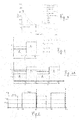
- fig. 12 The steps of one of the possible implementations are graphically represented in fig. 12 .
- the defined solutions D, f1 and f2 or, when applying the further optimization criteria D, f1 OPT and f2 OPT are indicated with the reference sign 1.
- the reference sign 2 is represented the following step, wherein the control period T has been sliced in ⁇ t/T control slices having time duration ⁇ t. After this operation, the slices have been permutated within the control period T.
- One of the possible permutation applicable according to the present invention is been represented in fig.12 and referenced with the sign 3.
- the short bars correspond to the time slices referred to the second fraction of the control period before the slicing operation, wherein only one burner is activated with a driving signal S1, S2 having frequency f2.
- the corresponding cycle skipping pattern is shown in the graphic 4.
Landscapes
- Physics & Mathematics (AREA)
- Electromagnetism (AREA)
- General Induction Heating (AREA)
- Cookers (AREA)
- Induction Heating Cooking Devices (AREA)
- Control Of High-Frequency Heating Circuits (AREA)
- Electric Stoves And Ranges (AREA)
- Electrical Discharge Machining, Electrochemical Machining, And Combined Machining (AREA)
Priority Applications (5)
| Application Number | Priority Date | Filing Date | Title |
|---|---|---|---|
| PL07101003.7T PL1951003T5 (pl) | 2007-01-23 | 2007-01-23 | Sposób sterowania indukcyjną płytą kuchenną i indukcyjna płyta kuchenna przystosowana do realizowania takiego sposobu |
| ES07101003T ES2338057T5 (es) | 2007-01-23 | 2007-01-23 | Método de control para una placa de cocina de inducción y placa de cocina de inducción adaptada para llevar a cabo dicho método |
| DE602007003672T DE602007003672D1 (de) | 2007-01-23 | 2007-01-23 | Verfahren zur Regelung eines Induktionskochfeldes und zur Ausführung dieses Verfahrens adaptiertes Induktionskochfeld |
| EP07101003.7A EP1951003B2 (fr) | 2007-01-23 | 2007-01-23 | Procédé de commande d'induction d'une plaque de cuisson et d'induction d'une plaque de cuisson adaptée à un tel procédé |
| AT07101003T ATE451819T1 (de) | 2007-01-23 | 2007-01-23 | Verfahren zur regelung eines induktionskochfeldes und zur ausführung dieses verfahrens adaptiertes induktionskochfeld |
Applications Claiming Priority (1)
| Application Number | Priority Date | Filing Date | Title |
|---|---|---|---|
| EP07101003.7A EP1951003B2 (fr) | 2007-01-23 | 2007-01-23 | Procédé de commande d'induction d'une plaque de cuisson et d'induction d'une plaque de cuisson adaptée à un tel procédé |
Publications (3)
| Publication Number | Publication Date |
|---|---|
| EP1951003A1 true EP1951003A1 (fr) | 2008-07-30 |
| EP1951003B1 EP1951003B1 (fr) | 2009-12-09 |
| EP1951003B2 EP1951003B2 (fr) | 2022-11-16 |
Family
ID=38226375
Family Applications (1)
| Application Number | Title | Priority Date | Filing Date |
|---|---|---|---|
| EP07101003.7A Active EP1951003B2 (fr) | 2007-01-23 | 2007-01-23 | Procédé de commande d'induction d'une plaque de cuisson et d'induction d'une plaque de cuisson adaptée à un tel procédé |
Country Status (5)
| Country | Link |
|---|---|
| EP (1) | EP1951003B2 (fr) |
| AT (1) | ATE451819T1 (fr) |
| DE (1) | DE602007003672D1 (fr) |
| ES (1) | ES2338057T5 (fr) |
| PL (1) | PL1951003T5 (fr) |
Cited By (38)
| Publication number | Priority date | Publication date | Assignee | Title |
|---|---|---|---|---|
| WO2010037675A1 (fr) * | 2008-09-30 | 2010-04-08 | BSH Bosch und Siemens Hausgeräte GmbH | Plaque de cuisson et procédé permettant de faire fonctionner une plaque de cuisson |
| EP2200399A1 (fr) * | 2008-12-22 | 2010-06-23 | FagorBrandt SAS | Procédé d'alimentation en puissance d'au moins un inducteur et appareil de cuisson mettant en oeuvre ledit procédé |
| EP2200398A1 (fr) * | 2008-12-22 | 2010-06-23 | FagorBrandt SAS | Procédé d'alimentation en puissance de deux inducteurs et appareil de cuisson mettant en oeuvre ledit procédé |
| EP2214454A1 (fr) | 2009-01-28 | 2010-08-04 | BSH Bosch und Siemens Hausgeräte GmbH | Champ de cuisson à induction doté de plusieurs inducteurs |
| EP2306784A1 (fr) | 2009-10-05 | 2011-04-06 | Whirlpool Corporation | Procédé de fourniture de puissance à des zones de cuisson par induction d'une plaque de cuisson par induction dotée d'une pluralité de convertisseurs de puissance, et plaque de cuisson par induction utilisant ledit procédé |
| EP2328384A1 (fr) * | 2009-11-27 | 2011-06-01 | Electrolux Home Products Corporation N.V. | Plaque de cuisson à induction et procédé de contrôle de plaque de cuisson à induction |
| FR2954886A1 (fr) * | 2009-12-31 | 2011-07-01 | Fagorbrandt Sas | Procede et dispositif de determination d'une puissance minimale continue induite, notamment dans un appareil de cuisson a induction |
| EP2445306A2 (fr) | 2010-10-21 | 2012-04-25 | FagorBrandt SAS | Procédé de commande en fonctionnement d'une table de cuisson à induction et table de cuisson à induction utilisant ce procédé |
| EP2469971A1 (fr) * | 2010-12-27 | 2012-06-27 | BSH Bosch und Siemens Hausgeräte GmbH | Dispositif d'appareil de cuisson |
| EP2469972A1 (fr) * | 2010-12-27 | 2012-06-27 | BSH Bosch und Siemens Hausgeräte GmbH | Dispositif d'appareil de cuisson |
| EP2506663A1 (fr) | 2011-03-28 | 2012-10-03 | BSH Bosch und Siemens Hausgeräte GmbH | Dispositif d'appareil de cuisson |
| EP2506664A1 (fr) | 2011-03-28 | 2012-10-03 | BSH Bosch und Siemens Hausgeräte GmbH | Dispositif d'appareil de cuisson |
| EP2506666A1 (fr) | 2011-03-28 | 2012-10-03 | BSH Bosch und Siemens Hausgeräte GmbH | Dispositif d'appareil de cuisson |
| US20120248098A1 (en) * | 2011-03-28 | 2012-10-04 | Samsung Electronics Co., Ltd. | Control method of induction heating cooker |
| EP2469970A3 (fr) * | 2010-12-27 | 2012-11-07 | BSH Bosch und Siemens Hausgeräte GmbH | Dispositif d'appareil de cuisson |
| EP2528412A1 (fr) * | 2010-01-20 | 2012-11-28 | Panasonic Corporation | Appareil de chauffage par induction |
| EP2506665A3 (fr) * | 2011-03-28 | 2013-05-08 | BSH Bosch und Siemens Hausgeräte GmbH | Dispositif d'appareil de cuisson |
| WO2013064967A3 (fr) * | 2011-11-04 | 2013-08-15 | BSH Bosch und Siemens Hausgeräte GmbH | Dispositif de chauffage par induction |
| WO2014072401A1 (fr) * | 2012-11-09 | 2014-05-15 | Electrolux Home Products Corporation N. V. | Procédé pour commander une plaque de cuisson à induction avec une pluralité de bobines d'induction et plaque de cuisson à induction |
| EP2787791A1 (fr) * | 2011-12-02 | 2014-10-08 | Panasonic Corporation | Dispositif de chauffage par induction |
| EP2790466A1 (fr) * | 2011-12-06 | 2014-10-15 | Panasonic Corporation | Dispositif de chauffage par induction |
| EP2911472A2 (fr) | 2013-12-20 | 2015-08-26 | BSH Hausgeräte GmbH | Dispositif d'appareil de cuisson, en particulier dispositif de plaque de cuisson, doté d'une pluralité d'onduleurs |
| EP2506667B1 (fr) | 2011-03-29 | 2016-10-19 | BSH Hausgeräte GmbH | Dispositif de chauffage à induction |
| EP3432685A1 (fr) * | 2017-07-18 | 2019-01-23 | Whirlpool Corporation | Procédé de fonctionnement d'une plaque de cuisson par induction et plaque de cuisson faisant appel à un tel procédé |
| WO2019135118A1 (fr) * | 2018-01-08 | 2019-07-11 | BSH Hausgeräte GmbH | Système de table de cuisson |
| ES2729728A1 (es) * | 2018-05-04 | 2019-11-05 | Bsh Electrodomesticos Espana Sa | Sistema de transmisión de energía por inducción |
| EP3641494A1 (fr) | 2018-10-17 | 2020-04-22 | BSH Hausgeräte GmbH | Dispositif formant appareil de cuisson |
| EP3641497A1 (fr) | 2018-10-17 | 2020-04-22 | BSH Hausgeräte GmbH | Dispositif formant appareil de cuisson |
| ES2764740A1 (es) * | 2018-12-04 | 2020-06-04 | Bsh Electrodomesticos Espana Sa | Dispositivo de aparato de cocción |
| WO2020229336A1 (fr) * | 2019-05-10 | 2020-11-19 | BSH Hausgeräte GmbH | Ensemble appareil de cuisson |
| EP3852492A1 (fr) * | 2018-10-18 | 2021-07-21 | Samsung Electronics Co., Ltd. | Appareil de cuisson et son procédé de commande |
| CN113475163A (zh) * | 2018-12-06 | 2021-10-01 | 伊利诺斯工具制品有限公司 | 降低控制rf施加以用于烹饪的可间歇操作芯片组上的热应力的功率控制解决方案 |
| EP4002955A1 (fr) * | 2020-11-13 | 2022-05-25 | Electrolux Appliances Aktiebolag | Unité de chauffage par induction, dispositif de cuisson par induction et procédé de fonctionnement d'une unité de chauffage par induction |
| EP4195875A1 (fr) | 2021-12-10 | 2023-06-14 | SABAF S.p.A. | Plaque de cuisson à induction et procédé de commande de plaque de cuisson à induction |
| WO2023043385A3 (fr) * | 2021-09-15 | 2023-06-29 | Mamur Teknoloji Sistemleri San. A.S. | Procédé de commande de circuit de puissance et de circuit de commande pour une plaque de cuisson à induction |
| DE102022202805A1 (de) | 2022-03-22 | 2023-09-28 | E.G.O. Elektro-Gerätebau GmbH | Verfahren zum Betrieb eines Induktionskochfelds und Induktionskochfeld |
| US11910509B2 (en) | 2021-03-02 | 2024-02-20 | Whirlpool Corporation | Method for improving accuracy in load curves acquisition on an induction cooktop |
| EP4383943A1 (fr) | 2022-12-09 | 2024-06-12 | SABAF S.p.A. | Table de cuisson à induction et procédé de commande d'une table de cuisson à induction |
Families Citing this family (7)
| Publication number | Priority date | Publication date | Assignee | Title |
|---|---|---|---|---|
| ES2602489T5 (es) | 2011-03-29 | 2024-04-30 | Bsh Hausgeraete Gmbh | Dispositivo de conmutación |
| ES2426871R1 (es) * | 2012-01-16 | 2013-11-27 | Bsh Electrodomesticos Espana | Dispositivo de encimera de coccion por induccion con un convertidor de corriente alterna y aparato domestico con dicho dispositivo |
| ES2564888B1 (es) | 2014-09-24 | 2017-01-05 | BSH Electrodomésticos España S.A. | Dispositivo de aparato de cocción y procedimiento para la puesta en funcionamiento de un dispositivo de aparato de cocción |
| ES2754813A1 (es) | 2018-10-17 | 2020-04-20 | Bsh Electrodomesticos Espana Sa | Dispositivo de Aparato de cocción |
| ES2764900A1 (es) | 2018-12-04 | 2020-06-04 | Bsh Electrodomesticos Espana Sa | Dispositivo de aparato de cocción |
| US20220191976A1 (en) | 2019-05-10 | 2022-06-16 | BSH Hausgeräte GmbH | Cooking appliance |
| FR3102335B1 (fr) | 2019-10-18 | 2023-05-26 | Groupe Brandt | Procédé de commande en puissance d'au moins un inducteur et appareil de cuisson à induction pour la mise en œuvre du procédé |
Citations (5)
| Publication number | Priority date | Publication date | Assignee | Title |
|---|---|---|---|---|
| EP0286044A2 (fr) * | 1987-04-10 | 1988-10-12 | Thomson Electromenager S.A. | Circuit pour l'alimentation en courant d'une plaque de cuisson par induction |
| EP0817531A2 (fr) * | 1996-06-26 | 1998-01-07 | Balay S.A. | Topologie flexible et reconfigurable |
| EP0844807A1 (fr) * | 1996-11-21 | 1998-05-27 | Balay S.A. | Commande optimale de la puissance installée dans une foyer de cuisson par induction avec une topologie reconfigurable |
| EP0926926A1 (fr) * | 1997-12-23 | 1999-06-30 | Compagnie Europeenne Pour L'equipement Menager "Cepem" | Dispositif d'alimentation de plusieurs circuits résonants par un générateur de puissance à onduleur |
| WO2006117182A1 (fr) * | 2005-05-04 | 2006-11-09 | E.G.O. Elektro-Gerätebau GmbH | Procede et dispositif d'alimentation electrique de plusieurs bobines d'induction d'un appareil d'induction |
Family Cites Families (8)
| Publication number | Priority date | Publication date | Assignee | Title |
|---|---|---|---|---|
| JPH0612699B2 (ja) † | 1985-11-27 | 1994-02-16 | 株式会社東芝 | 誘導加熱調理器 |
| GB2203605B (en) † | 1987-04-07 | 1991-01-09 | Toshiba Kk | Electromagnetic induction heating apparatus capable of preventing undesirable states of cooking utensils or vessels |
| DE3726535A1 (de) † | 1987-08-10 | 1989-02-23 | Philips Patentverwaltung | Verfahren zur schaltstossarmen leistungssteuerung elektrischer lasten |
| JP3785647B2 (ja) † | 1995-02-08 | 2006-06-14 | 松下電器産業株式会社 | 多口誘導加熱調理器 |
| JP3711483B2 (ja) † | 1998-07-17 | 2005-11-02 | 三菱電機株式会社 | 誘導加熱調理器 |
| FR2839605B1 (fr) † | 2002-05-07 | 2004-09-10 | Elka | Module de cuisson electrique a induction et procede de commande du module |
| ES2201937B1 (es) † | 2003-11-03 | 2005-02-01 | Bsh Electrodomesticos España, S.A. | Procedimiento para el funcionamiento de un circuito convertidor. |
| JP4345775B2 (ja) † | 2006-06-07 | 2009-10-14 | パナソニック株式会社 | 誘導加熱調理器 |
-
2007
- 2007-01-23 ES ES07101003T patent/ES2338057T5/es active Active
- 2007-01-23 EP EP07101003.7A patent/EP1951003B2/fr active Active
- 2007-01-23 AT AT07101003T patent/ATE451819T1/de not_active IP Right Cessation
- 2007-01-23 DE DE602007003672T patent/DE602007003672D1/de active Active
- 2007-01-23 PL PL07101003.7T patent/PL1951003T5/pl unknown
Patent Citations (5)
| Publication number | Priority date | Publication date | Assignee | Title |
|---|---|---|---|---|
| EP0286044A2 (fr) * | 1987-04-10 | 1988-10-12 | Thomson Electromenager S.A. | Circuit pour l'alimentation en courant d'une plaque de cuisson par induction |
| EP0817531A2 (fr) * | 1996-06-26 | 1998-01-07 | Balay S.A. | Topologie flexible et reconfigurable |
| EP0844807A1 (fr) * | 1996-11-21 | 1998-05-27 | Balay S.A. | Commande optimale de la puissance installée dans une foyer de cuisson par induction avec une topologie reconfigurable |
| EP0926926A1 (fr) * | 1997-12-23 | 1999-06-30 | Compagnie Europeenne Pour L'equipement Menager "Cepem" | Dispositif d'alimentation de plusieurs circuits résonants par un générateur de puissance à onduleur |
| WO2006117182A1 (fr) * | 2005-05-04 | 2006-11-09 | E.G.O. Elektro-Gerätebau GmbH | Procede et dispositif d'alimentation electrique de plusieurs bobines d'induction d'un appareil d'induction |
Cited By (71)
| Publication number | Priority date | Publication date | Assignee | Title |
|---|---|---|---|---|
| US9609697B2 (en) * | 2008-09-30 | 2017-03-28 | BSH Hausgeräte GmbH | Cooktop and method for operating a cooktop |
| CN102172100B (zh) * | 2008-09-30 | 2013-10-30 | Bsh博施及西门子家用器具有限公司 | 灶和灶的操作方法 |
| US20110163086A1 (en) * | 2008-09-30 | 2011-07-07 | BSH Bosch und Siemens Hausgeräte GmbH | Cooktop and method for operating a cooktop |
| CN102172100A (zh) * | 2008-09-30 | 2011-08-31 | Bsh博施及西门子家用器具有限公司 | 灶和灶的操作方法 |
| WO2010037675A1 (fr) * | 2008-09-30 | 2010-04-08 | BSH Bosch und Siemens Hausgeräte GmbH | Plaque de cuisson et procédé permettant de faire fonctionner une plaque de cuisson |
| EP2200399A1 (fr) * | 2008-12-22 | 2010-06-23 | FagorBrandt SAS | Procédé d'alimentation en puissance d'au moins un inducteur et appareil de cuisson mettant en oeuvre ledit procédé |
| EP2200398A1 (fr) * | 2008-12-22 | 2010-06-23 | FagorBrandt SAS | Procédé d'alimentation en puissance de deux inducteurs et appareil de cuisson mettant en oeuvre ledit procédé |
| EP2214454A1 (fr) | 2009-01-28 | 2010-08-04 | BSH Bosch und Siemens Hausgeräte GmbH | Champ de cuisson à induction doté de plusieurs inducteurs |
| EP3771288A1 (fr) | 2009-10-05 | 2021-01-27 | Whirlpool Corporation | Procédé de fourniture de puissance à des zones de cuisson par induction d'une plaque de cuisson par induction dotée d'une pluralité de convertisseurs de puissance, et plaque de cuisson par induction utilisant ledit procédé |
| EP2306784A1 (fr) | 2009-10-05 | 2011-04-06 | Whirlpool Corporation | Procédé de fourniture de puissance à des zones de cuisson par induction d'une plaque de cuisson par induction dotée d'une pluralité de convertisseurs de puissance, et plaque de cuisson par induction utilisant ledit procédé |
| US8686321B2 (en) | 2009-10-05 | 2014-04-01 | Whirlpool Corporation | Method for supplying power to induction cooking zones of an induction cooking hob having a plurality of power converters, and induction cooking hob using such method |
| EP3771288B1 (fr) | 2009-10-05 | 2021-12-15 | Whirlpool Corporation | Procédé de fourniture de puissance à des zones de cuisson par induction d'une plaque de cuisson par induction dotée d'une pluralité de convertisseurs de puissance, et plaque de cuisson par induction utilisant ledit procédé |
| AU2010324115B2 (en) * | 2009-11-27 | 2014-09-25 | Electrolux Home Products Corporation N. V. | An induction hob and a method for controlling an induction hob |
| US9693396B2 (en) | 2009-11-27 | 2017-06-27 | Electrolux Home Products Corporation N.V. | Induction hob and a method for controlling an induction hob |
| CN102612855B (zh) * | 2009-11-27 | 2015-06-10 | 伊莱克斯家用产品股份有限公司 | 感应炉及控制感应炉的方法 |
| CN102612855A (zh) * | 2009-11-27 | 2012-07-25 | 伊莱克斯家用产品股份有限公司 | 感应炉及控制感应炉的方法 |
| WO2011063954A1 (fr) * | 2009-11-27 | 2011-06-03 | Electrolux Home Products Corporation N. V. | Plaque de cuisson à induction et procédé de commande d'une plaque de cuisson à induction |
| EP2328384A1 (fr) * | 2009-11-27 | 2011-06-01 | Electrolux Home Products Corporation N.V. | Plaque de cuisson à induction et procédé de contrôle de plaque de cuisson à induction |
| EP2341757A1 (fr) * | 2009-12-31 | 2011-07-06 | FagorBrandt SAS | Procédé et dispositif de détermination d'une puissance minimale continue induite, notamment dans un appareil de cuisson à induction |
| FR2954886A1 (fr) * | 2009-12-31 | 2011-07-01 | Fagorbrandt Sas | Procede et dispositif de determination d'une puissance minimale continue induite, notamment dans un appareil de cuisson a induction |
| EP2528412A1 (fr) * | 2010-01-20 | 2012-11-28 | Panasonic Corporation | Appareil de chauffage par induction |
| EP2528412A4 (fr) * | 2010-01-20 | 2014-01-22 | Panasonic Corp | Appareil de chauffage par induction |
| FR2966688A1 (fr) * | 2010-10-21 | 2012-04-27 | Fagorbrandt Sas | Procede de commande en fonctionnement d'une table de cuisson a induction et table de cuisson a induction utilisant ce procede. |
| EP2445306A2 (fr) | 2010-10-21 | 2012-04-25 | FagorBrandt SAS | Procédé de commande en fonctionnement d'une table de cuisson à induction et table de cuisson à induction utilisant ce procédé |
| EP2445306A3 (fr) * | 2010-10-21 | 2012-12-26 | FagorBrandt SAS | Procédé de commande en fonctionnement d'une table de cuisson à induction et table de cuisson à induction utilisant ce procédé |
| EP2469970A3 (fr) * | 2010-12-27 | 2012-11-07 | BSH Bosch und Siemens Hausgeräte GmbH | Dispositif d'appareil de cuisson |
| EP2469972A1 (fr) * | 2010-12-27 | 2012-06-27 | BSH Bosch und Siemens Hausgeräte GmbH | Dispositif d'appareil de cuisson |
| EP2469971A1 (fr) * | 2010-12-27 | 2012-06-27 | BSH Bosch und Siemens Hausgeräte GmbH | Dispositif d'appareil de cuisson |
| EP2506668A3 (fr) * | 2011-03-28 | 2013-05-15 | Samsung Electronics Co., Ltd. | Procédé de commande d'appareil de cuisson à chauffage par induction |
| EP2506665A3 (fr) * | 2011-03-28 | 2013-05-08 | BSH Bosch und Siemens Hausgeräte GmbH | Dispositif d'appareil de cuisson |
| US20120248098A1 (en) * | 2011-03-28 | 2012-10-04 | Samsung Electronics Co., Ltd. | Control method of induction heating cooker |
| EP2506666A1 (fr) | 2011-03-28 | 2012-10-03 | BSH Bosch und Siemens Hausgeräte GmbH | Dispositif d'appareil de cuisson |
| EP2506664A1 (fr) | 2011-03-28 | 2012-10-03 | BSH Bosch und Siemens Hausgeräte GmbH | Dispositif d'appareil de cuisson |
| EP3270661A1 (fr) * | 2011-03-28 | 2018-01-17 | Samsung Electronics Co., Ltd. | Procédé de commande d'appareil de cuisson à chauffage par induction |
| EP2506663A1 (fr) | 2011-03-28 | 2012-10-03 | BSH Bosch und Siemens Hausgeräte GmbH | Dispositif d'appareil de cuisson |
| EP2506667B1 (fr) | 2011-03-29 | 2016-10-19 | BSH Hausgeräte GmbH | Dispositif de chauffage à induction |
| CN103891401A (zh) * | 2011-11-04 | 2014-06-25 | Bsh博世和西门子家用电器有限公司 | 感应加热装置 |
| CN103891401B (zh) * | 2011-11-04 | 2016-03-09 | Bsh家用电器有限公司 | 感应加热装置 |
| WO2013064967A3 (fr) * | 2011-11-04 | 2013-08-15 | BSH Bosch und Siemens Hausgeräte GmbH | Dispositif de chauffage par induction |
| JPWO2013080401A1 (ja) * | 2011-12-02 | 2015-04-27 | パナソニックIpマネジメント株式会社 | 誘導加熱装置 |
| EP2787791A4 (fr) * | 2011-12-02 | 2015-04-15 | Panasonic Corp | Dispositif de chauffage par induction |
| US9313831B2 (en) | 2011-12-02 | 2016-04-12 | Panasonic Intellectual Property Management Co., Ltd. | Induction heating apparatus capable of avoiding unstable heating due to limitation of heating output |
| EP2787791A1 (fr) * | 2011-12-02 | 2014-10-08 | Panasonic Corporation | Dispositif de chauffage par induction |
| EP2790466A1 (fr) * | 2011-12-06 | 2014-10-15 | Panasonic Corporation | Dispositif de chauffage par induction |
| US9554425B2 (en) | 2011-12-06 | 2017-01-24 | Panasonic Intellectual Property Management Co., Ltd. | Induction heating device |
| EP2790466A4 (fr) * | 2011-12-06 | 2015-04-22 | Panasonic Corp | Dispositif de chauffage par induction |
| US10244584B2 (en) | 2012-11-09 | 2019-03-26 | Electrolux Home Products Corporation N.V. | Method for controlling an induction cooking hob with a plurality of induction coils and an induction cooking hob |
| WO2014072401A1 (fr) * | 2012-11-09 | 2014-05-15 | Electrolux Home Products Corporation N. V. | Procédé pour commander une plaque de cuisson à induction avec une pluralité de bobines d'induction et plaque de cuisson à induction |
| EP2911472A2 (fr) | 2013-12-20 | 2015-08-26 | BSH Hausgeräte GmbH | Dispositif d'appareil de cuisson, en particulier dispositif de plaque de cuisson, doté d'une pluralité d'onduleurs |
| EP2911472B1 (fr) | 2013-12-20 | 2020-03-11 | BSH Hausgeräte GmbH | Dispositif d'appareil de cuisson, en particulier dispositif de plaque de cuisson, doté d'une pluralité d'onduleurs |
| EP2911472B2 (fr) † | 2013-12-20 | 2022-11-09 | BSH Hausgeräte GmbH | Dispositif d'appareil de cuisson, en particulier dispositif de plaque de cuisson, doté d'une pluralité d'onduleurs |
| US10893579B2 (en) | 2017-07-18 | 2021-01-12 | Whirlpool Corporation | Method for operating an induction cooking hob and cooking hob using such method |
| EP3432685A1 (fr) * | 2017-07-18 | 2019-01-23 | Whirlpool Corporation | Procédé de fonctionnement d'une plaque de cuisson par induction et plaque de cuisson faisant appel à un tel procédé |
| US20190029079A1 (en) * | 2017-07-18 | 2019-01-24 | Whirlpool Corporation | Method for operating an induction cooking hob and cooking hob using such method |
| WO2019135118A1 (fr) * | 2018-01-08 | 2019-07-11 | BSH Hausgeräte GmbH | Système de table de cuisson |
| ES2729728A1 (es) * | 2018-05-04 | 2019-11-05 | Bsh Electrodomesticos Espana Sa | Sistema de transmisión de energía por inducción |
| EP3641497A1 (fr) | 2018-10-17 | 2020-04-22 | BSH Hausgeräte GmbH | Dispositif formant appareil de cuisson |
| EP3641494A1 (fr) | 2018-10-17 | 2020-04-22 | BSH Hausgeräte GmbH | Dispositif formant appareil de cuisson |
| EP3852492A1 (fr) * | 2018-10-18 | 2021-07-21 | Samsung Electronics Co., Ltd. | Appareil de cuisson et son procédé de commande |
| EP3852492A4 (fr) * | 2018-10-18 | 2021-11-03 | Samsung Electronics Co., Ltd. | Appareil de cuisson et son procédé de commande |
| US12096539B2 (en) | 2018-10-18 | 2024-09-17 | Samsung Electronics Co., Ltd. | Cooking apparatus and control method therefor |
| ES2764740A1 (es) * | 2018-12-04 | 2020-06-04 | Bsh Electrodomesticos Espana Sa | Dispositivo de aparato de cocción |
| EP3664578A1 (fr) * | 2018-12-04 | 2020-06-10 | BSH Hausgeräte GmbH | Dispositif formant appareil de cuisson |
| CN113475163A (zh) * | 2018-12-06 | 2021-10-01 | 伊利诺斯工具制品有限公司 | 降低控制rf施加以用于烹饪的可间歇操作芯片组上的热应力的功率控制解决方案 |
| WO2020229336A1 (fr) * | 2019-05-10 | 2020-11-19 | BSH Hausgeräte GmbH | Ensemble appareil de cuisson |
| EP4002955A1 (fr) * | 2020-11-13 | 2022-05-25 | Electrolux Appliances Aktiebolag | Unité de chauffage par induction, dispositif de cuisson par induction et procédé de fonctionnement d'une unité de chauffage par induction |
| US11910509B2 (en) | 2021-03-02 | 2024-02-20 | Whirlpool Corporation | Method for improving accuracy in load curves acquisition on an induction cooktop |
| WO2023043385A3 (fr) * | 2021-09-15 | 2023-06-29 | Mamur Teknoloji Sistemleri San. A.S. | Procédé de commande de circuit de puissance et de circuit de commande pour une plaque de cuisson à induction |
| EP4195875A1 (fr) | 2021-12-10 | 2023-06-14 | SABAF S.p.A. | Plaque de cuisson à induction et procédé de commande de plaque de cuisson à induction |
| DE102022202805A1 (de) | 2022-03-22 | 2023-09-28 | E.G.O. Elektro-Gerätebau GmbH | Verfahren zum Betrieb eines Induktionskochfelds und Induktionskochfeld |
| EP4383943A1 (fr) | 2022-12-09 | 2024-06-12 | SABAF S.p.A. | Table de cuisson à induction et procédé de commande d'une table de cuisson à induction |
Also Published As
| Publication number | Publication date |
|---|---|
| EP1951003B2 (fr) | 2022-11-16 |
| ES2338057T3 (es) | 2010-05-03 |
| PL1951003T3 (pl) | 2010-06-30 |
| ATE451819T1 (de) | 2009-12-15 |
| EP1951003B1 (fr) | 2009-12-09 |
| PL1951003T5 (pl) | 2023-08-21 |
| DE602007003672D1 (de) | 2010-01-21 |
| ES2338057T5 (es) | 2023-03-09 |
Similar Documents
| Publication | Publication Date | Title |
|---|---|---|
| EP1951003B1 (fr) | Procédé de commande d'induction d'une plaque de cuisson et d'induction d'une plaque de cuisson adaptée à un tel procédé | |
| CA2710997C (fr) | Methode d'alimentation des zones de cuisson par induction d'un plan de cuisson par induction pourvu de convertisseurs de secteur, plan de cuisson par induction faisant appel a cette methode | |
| Lucia et al. | Load-adaptive control algorithm of half-bridge series resonant inverter for domestic induction heating | |
| US3786219A (en) | Solid state induction cooking systems for ranges and surface cooking units | |
| EP3432685B1 (fr) | Procédé de fonctionnement d'une plaque de cuisson par induction et plaque de cuisson faisant appel à un tel procédé | |
| US4112287A (en) | Central oscillator for induction range using triac burner controls | |
| CN101574014B (zh) | 用于控制感应灶具的方法和感应灶具 | |
| CN103416104A (zh) | 感应加热装置 | |
| EP2525485B1 (fr) | Methode pour etendre la plage de réglage d' onduleurs quasi-resonants | |
| JPWO2013061595A1 (ja) | 誘導加熱装置 | |
| US11064573B2 (en) | Determining resonant frequency for quasi-resonant induction cooking devices | |
| Sadakata et al. | Latest practical developments of triplex series load resonant frequency-operated high frequency inverter for induction-heated low resistivity metallic appliances in consumer built-in cooktops | |
| Fujita et al. | Latest developments of high-frequency series load resonant inverter type built-in cooktops for induction heated all metallic appliances | |
| EP2836053A1 (fr) | Plaque de cuisson à induction et procédé pour faire fonctionner une telle plaque | |
| US20180176998A1 (en) | Evaluating zero-voltage switching condition of quasi-resonant inverters in induction cooktops | |
| CN107787603B (zh) | 用于控制包括多个感应线圈的感应烹饪灶具的方法 | |
| JP5223315B2 (ja) | 誘導加熱装置 | |
| JP7344740B2 (ja) | 電磁誘導加熱装置 | |
| KR102142412B1 (ko) | Emi를 감소시킨 조리 기기 및 그 동작방법 | |
| KR102175634B1 (ko) | 동작 안정성을 향상한 조리 기기 및 그 동작방법 | |
| JP2005149737A (ja) | 誘導加熱装置 | |
| EP4002955B1 (fr) | Unité de chauffage par induction, dispositif de cuisson par induction et procédé de fonctionnement d'une unité de chauffage par induction | |
| KR101846358B1 (ko) | 복수의 인버터 회로가 동일 주파수로 동작하는 전기 레인지 및 전기 레인지의 제어 방법 | |
| CN111246611B (zh) | 一种电磁加热烹饪器具 | |
| CN112888100B (zh) | 半桥电磁器具的电磁加热控制方法和半桥电磁器具 |
Legal Events
| Date | Code | Title | Description |
|---|---|---|---|
| PUAI | Public reference made under article 153(3) epc to a published international application that has entered the european phase |
Free format text: ORIGINAL CODE: 0009012 |
|
| AK | Designated contracting states |
Kind code of ref document: A1 Designated state(s): AT BE BG CH CY CZ DE DK EE ES FI FR GB GR HU IE IS IT LI LT LU LV MC NL PL PT RO SE SI SK TR |
|
| AX | Request for extension of the european patent |
Extension state: AL BA HR MK RS |
|
| 17P | Request for examination filed |
Effective date: 20081212 |
|
| 17Q | First examination report despatched |
Effective date: 20090130 |
|
| AKX | Designation fees paid |
Designated state(s): AT BE BG CH CY CZ DE DK EE ES FI FR GB GR HU IE IS IT LI LT LU LV MC NL PL PT RO SE SI SK TR |
|
| GRAP | Despatch of communication of intention to grant a patent |
Free format text: ORIGINAL CODE: EPIDOSNIGR1 |
|
| GRAS | Grant fee paid |
Free format text: ORIGINAL CODE: EPIDOSNIGR3 |
|
| GRAA | (expected) grant |
Free format text: ORIGINAL CODE: 0009210 |
|
| STAA | Information on the status of an ep patent application or granted ep patent |
Free format text: STATUS: THE PATENT HAS BEEN GRANTED |
|
| AK | Designated contracting states |
Kind code of ref document: B1 Designated state(s): AT BE BG CH CY CZ DE DK EE ES FI FR GB GR HU IE IS IT LI LT LU LV MC NL PL PT RO SE SI SK TR |
|
| REG | Reference to a national code |
Ref country code: GB Ref legal event code: FG4D |
|
| REG | Reference to a national code |
Ref country code: CH Ref legal event code: EP |
|
| REG | Reference to a national code |
Ref country code: IE Ref legal event code: FG4D |
|
| REF | Corresponds to: |
Ref document number: 602007003672 Country of ref document: DE Date of ref document: 20100121 Kind code of ref document: P |
|
| REG | Reference to a national code |
Ref country code: NL Ref legal event code: VDEP Effective date: 20091209 |
|
| PG25 | Lapsed in a contracting state [announced via postgrant information from national office to epo] |
Ref country code: SE Free format text: LAPSE BECAUSE OF FAILURE TO SUBMIT A TRANSLATION OF THE DESCRIPTION OR TO PAY THE FEE WITHIN THE PRESCRIBED TIME-LIMIT Effective date: 20091209 Ref country code: LT Free format text: LAPSE BECAUSE OF FAILURE TO SUBMIT A TRANSLATION OF THE DESCRIPTION OR TO PAY THE FEE WITHIN THE PRESCRIBED TIME-LIMIT Effective date: 20091209 Ref country code: FI Free format text: LAPSE BECAUSE OF FAILURE TO SUBMIT A TRANSLATION OF THE DESCRIPTION OR TO PAY THE FEE WITHIN THE PRESCRIBED TIME-LIMIT Effective date: 20091209 |
|
| REG | Reference to a national code |
Ref country code: ES Ref legal event code: FG2A Ref document number: 2338057 Country of ref document: ES Kind code of ref document: T3 |
|
| LTIE | Lt: invalidation of european patent or patent extension |
Effective date: 20091209 |
|
| PG25 | Lapsed in a contracting state [announced via postgrant information from national office to epo] |
Ref country code: SI Free format text: LAPSE BECAUSE OF FAILURE TO SUBMIT A TRANSLATION OF THE DESCRIPTION OR TO PAY THE FEE WITHIN THE PRESCRIBED TIME-LIMIT Effective date: 20091209 Ref country code: LV Free format text: LAPSE BECAUSE OF FAILURE TO SUBMIT A TRANSLATION OF THE DESCRIPTION OR TO PAY THE FEE WITHIN THE PRESCRIBED TIME-LIMIT Effective date: 20091209 |
|
| PG25 | Lapsed in a contracting state [announced via postgrant information from national office to epo] |
Ref country code: AT Free format text: LAPSE BECAUSE OF FAILURE TO SUBMIT A TRANSLATION OF THE DESCRIPTION OR TO PAY THE FEE WITHIN THE PRESCRIBED TIME-LIMIT Effective date: 20091209 |
|
| PG25 | Lapsed in a contracting state [announced via postgrant information from national office to epo] |
Ref country code: RO Free format text: LAPSE BECAUSE OF FAILURE TO SUBMIT A TRANSLATION OF THE DESCRIPTION OR TO PAY THE FEE WITHIN THE PRESCRIBED TIME-LIMIT Effective date: 20091209 Ref country code: PT Free format text: LAPSE BECAUSE OF FAILURE TO SUBMIT A TRANSLATION OF THE DESCRIPTION OR TO PAY THE FEE WITHIN THE PRESCRIBED TIME-LIMIT Effective date: 20100409 Ref country code: NL Free format text: LAPSE BECAUSE OF FAILURE TO SUBMIT A TRANSLATION OF THE DESCRIPTION OR TO PAY THE FEE WITHIN THE PRESCRIBED TIME-LIMIT Effective date: 20091209 Ref country code: IS Free format text: LAPSE BECAUSE OF FAILURE TO SUBMIT A TRANSLATION OF THE DESCRIPTION OR TO PAY THE FEE WITHIN THE PRESCRIBED TIME-LIMIT Effective date: 20100409 Ref country code: EE Free format text: LAPSE BECAUSE OF FAILURE TO SUBMIT A TRANSLATION OF THE DESCRIPTION OR TO PAY THE FEE WITHIN THE PRESCRIBED TIME-LIMIT Effective date: 20091209 Ref country code: BG Free format text: LAPSE BECAUSE OF FAILURE TO SUBMIT A TRANSLATION OF THE DESCRIPTION OR TO PAY THE FEE WITHIN THE PRESCRIBED TIME-LIMIT Effective date: 20100309 |
|
| PG25 | Lapsed in a contracting state [announced via postgrant information from national office to epo] |
Ref country code: SK Free format text: LAPSE BECAUSE OF FAILURE TO SUBMIT A TRANSLATION OF THE DESCRIPTION OR TO PAY THE FEE WITHIN THE PRESCRIBED TIME-LIMIT Effective date: 20091209 Ref country code: MC Free format text: LAPSE BECAUSE OF NON-PAYMENT OF DUE FEES Effective date: 20100131 Ref country code: CZ Free format text: LAPSE BECAUSE OF FAILURE TO SUBMIT A TRANSLATION OF THE DESCRIPTION OR TO PAY THE FEE WITHIN THE PRESCRIBED TIME-LIMIT Effective date: 20091209 Ref country code: BE Free format text: LAPSE BECAUSE OF FAILURE TO SUBMIT A TRANSLATION OF THE DESCRIPTION OR TO PAY THE FEE WITHIN THE PRESCRIBED TIME-LIMIT Effective date: 20091209 |
|
| PLBI | Opposition filed |
Free format text: ORIGINAL CODE: 0009260 |
|
| PLBI | Opposition filed |
Free format text: ORIGINAL CODE: 0009260 |
|
| PLAX | Notice of opposition and request to file observation + time limit sent |
Free format text: ORIGINAL CODE: EPIDOSNOBS2 |
|
| 26 | Opposition filed |
Opponent name: KILBURN & STRODE LLP Effective date: 20100908 |
|
| 26 | Opposition filed |
Opponent name: ELECTROLUX ROTHENBURG GMBH FACTORY AND DEVELOPMENT Effective date: 20100909 Opponent name: KILBURN & STRODE LLP Effective date: 20100908 |
|
| PG25 | Lapsed in a contracting state [announced via postgrant information from national office to epo] |
Ref country code: GR Free format text: LAPSE BECAUSE OF FAILURE TO SUBMIT A TRANSLATION OF THE DESCRIPTION OR TO PAY THE FEE WITHIN THE PRESCRIBED TIME-LIMIT Effective date: 20100310 Ref country code: CY Free format text: LAPSE BECAUSE OF FAILURE TO SUBMIT A TRANSLATION OF THE DESCRIPTION OR TO PAY THE FEE WITHIN THE PRESCRIBED TIME-LIMIT Effective date: 20091209 |
|
| PG25 | Lapsed in a contracting state [announced via postgrant information from national office to epo] |
Ref country code: IE Free format text: LAPSE BECAUSE OF NON-PAYMENT OF DUE FEES Effective date: 20100123 Ref country code: DK Free format text: LAPSE BECAUSE OF FAILURE TO SUBMIT A TRANSLATION OF THE DESCRIPTION OR TO PAY THE FEE WITHIN THE PRESCRIBED TIME-LIMIT Effective date: 20091209 |
|
| PLBB | Reply of patent proprietor to notice(s) of opposition received |
Free format text: ORIGINAL CODE: EPIDOSNOBS3 |
|
| PGRI | Patent reinstated in contracting state [announced from national office to epo] |
Ref country code: IT Effective date: 20110501 |
|
| REG | Reference to a national code |
Ref country code: CH Ref legal event code: PL |
|
| PG25 | Lapsed in a contracting state [announced via postgrant information from national office to epo] |
Ref country code: CH Free format text: LAPSE BECAUSE OF NON-PAYMENT OF DUE FEES Effective date: 20110131 Ref country code: LI Free format text: LAPSE BECAUSE OF NON-PAYMENT OF DUE FEES Effective date: 20110131 |
|
| PG25 | Lapsed in a contracting state [announced via postgrant information from national office to epo] |
Ref country code: HU Free format text: LAPSE BECAUSE OF FAILURE TO SUBMIT A TRANSLATION OF THE DESCRIPTION OR TO PAY THE FEE WITHIN THE PRESCRIBED TIME-LIMIT Effective date: 20100610 Ref country code: LU Free format text: LAPSE BECAUSE OF NON-PAYMENT OF DUE FEES Effective date: 20100123 |
|
| PG25 | Lapsed in a contracting state [announced via postgrant information from national office to epo] |
Ref country code: TR Free format text: LAPSE BECAUSE OF FAILURE TO SUBMIT A TRANSLATION OF THE DESCRIPTION OR TO PAY THE FEE WITHIN THE PRESCRIBED TIME-LIMIT Effective date: 20091209 |
|
| APAH | Appeal reference modified |
Free format text: ORIGINAL CODE: EPIDOSCREFNO |
|
| APBM | Appeal reference recorded |
Free format text: ORIGINAL CODE: EPIDOSNREFNO |
|
| APBP | Date of receipt of notice of appeal recorded |
Free format text: ORIGINAL CODE: EPIDOSNNOA2O |
|
| APBM | Appeal reference recorded |
Free format text: ORIGINAL CODE: EPIDOSNREFNO |
|
| APBP | Date of receipt of notice of appeal recorded |
Free format text: ORIGINAL CODE: EPIDOSNNOA2O |
|
| APBQ | Date of receipt of statement of grounds of appeal recorded |
Free format text: ORIGINAL CODE: EPIDOSNNOA3O |
|
| APBQ | Date of receipt of statement of grounds of appeal recorded |
Free format text: ORIGINAL CODE: EPIDOSNNOA3O |
|
| REG | Reference to a national code |
Ref country code: FR Ref legal event code: PLFP Year of fee payment: 10 |
|
| REG | Reference to a national code |
Ref country code: FR Ref legal event code: PLFP Year of fee payment: 11 |
|
| REG | Reference to a national code |
Ref country code: FR Ref legal event code: PLFP Year of fee payment: 12 |
|
| APAH | Appeal reference modified |
Free format text: ORIGINAL CODE: EPIDOSCREFNO |
|
| PLAB | Opposition data, opponent's data or that of the opponent's representative modified |
Free format text: ORIGINAL CODE: 0009299OPPO |
|
| R26 | Opposition filed (corrected) |
Opponent name: KILBURN & STRODE LLP Effective date: 20100908 |
|
| APBU | Appeal procedure closed |
Free format text: ORIGINAL CODE: EPIDOSNNOA9O |
|
| PUAH | Patent maintained in amended form |
Free format text: ORIGINAL CODE: 0009272 |
|
| STAA | Information on the status of an ep patent application or granted ep patent |
Free format text: STATUS: PATENT MAINTAINED AS AMENDED |
|
| 27A | Patent maintained in amended form |
Effective date: 20221116 |
|
| AK | Designated contracting states |
Kind code of ref document: B2 Designated state(s): AT BE BG CH CY CZ DE DK EE ES FI FR GB GR HU IE IS IT LI LT LU LV MC NL PL PT RO SE SI SK TR |
|
| REG | Reference to a national code |
Ref country code: DE Ref legal event code: R102 Ref document number: 602007003672 Country of ref document: DE |
|
| REG | Reference to a national code |
Ref country code: ES Ref legal event code: DC2A Ref document number: 2338057 Country of ref document: ES Kind code of ref document: T5 Effective date: 20230309 |
|
| P01 | Opt-out of the competence of the unified patent court (upc) registered |
Effective date: 20230522 |
|
| PGFP | Annual fee paid to national office [announced via postgrant information from national office to epo] |
Ref country code: PL Payment date: 20231228 Year of fee payment: 18 |
|
| PGFP | Annual fee paid to national office [announced via postgrant information from national office to epo] |
Ref country code: ES Payment date: 20240209 Year of fee payment: 18 |
|
| PGFP | Annual fee paid to national office [announced via postgrant information from national office to epo] |
Ref country code: DE Payment date: 20240129 Year of fee payment: 18 Ref country code: GB Payment date: 20240123 Year of fee payment: 18 |
|
| PGFP | Annual fee paid to national office [announced via postgrant information from national office to epo] |
Ref country code: IT Payment date: 20240123 Year of fee payment: 18 Ref country code: FR Payment date: 20240125 Year of fee payment: 18 |