EP1950772B1 - Magnetic core and position indicator - Google Patents
Magnetic core and position indicator Download PDFInfo
- Publication number
- EP1950772B1 EP1950772B1 EP08100725.4A EP08100725A EP1950772B1 EP 1950772 B1 EP1950772 B1 EP 1950772B1 EP 08100725 A EP08100725 A EP 08100725A EP 1950772 B1 EP1950772 B1 EP 1950772B1
- Authority
- EP
- European Patent Office
- Prior art keywords
- position indicator
- core
- magnetic core
- coil
- pen
- Prior art date
- Legal status (The legal status is an assumption and is not a legal conclusion. Google has not performed a legal analysis and makes no representation as to the accuracy of the status listed.)
- Ceased
Links
Images


Classifications
-
- H—ELECTRICITY
- H01—ELECTRIC ELEMENTS
- H01F—MAGNETS; INDUCTANCES; TRANSFORMERS; SELECTION OF MATERIALS FOR THEIR MAGNETIC PROPERTIES
- H01F41/00—Apparatus or processes specially adapted for manufacturing or assembling magnets, inductances or transformers; Apparatus or processes specially adapted for manufacturing materials characterised by their magnetic properties
- H01F41/02—Apparatus or processes specially adapted for manufacturing or assembling magnets, inductances or transformers; Apparatus or processes specially adapted for manufacturing materials characterised by their magnetic properties for manufacturing cores, coils, or magnets
- H01F41/0206—Manufacturing of magnetic cores by mechanical means
- H01F41/0246—Manufacturing of magnetic circuits by moulding or by pressing powder
-
- G—PHYSICS
- G01—MEASURING; TESTING
- G01D—MEASURING NOT SPECIALLY ADAPTED FOR A SPECIFIC VARIABLE; ARRANGEMENTS FOR MEASURING TWO OR MORE VARIABLES NOT COVERED IN A SINGLE OTHER SUBCLASS; TARIFF METERING APPARATUS; MEASURING OR TESTING NOT OTHERWISE PROVIDED FOR
- G01D5/00—Mechanical means for transferring the output of a sensing member; Means for converting the output of a sensing member to another variable where the form or nature of the sensing member does not constrain the means for converting; Transducers not specially adapted for a specific variable
- G01D5/12—Mechanical means for transferring the output of a sensing member; Means for converting the output of a sensing member to another variable where the form or nature of the sensing member does not constrain the means for converting; Transducers not specially adapted for a specific variable using electric or magnetic means
- G01D5/14—Mechanical means for transferring the output of a sensing member; Means for converting the output of a sensing member to another variable where the form or nature of the sensing member does not constrain the means for converting; Transducers not specially adapted for a specific variable using electric or magnetic means influencing the magnitude of a current or voltage
- G01D5/20—Mechanical means for transferring the output of a sensing member; Means for converting the output of a sensing member to another variable where the form or nature of the sensing member does not constrain the means for converting; Transducers not specially adapted for a specific variable using electric or magnetic means influencing the magnitude of a current or voltage by varying inductance, e.g. by a movable armature
- G01D5/204—Mechanical means for transferring the output of a sensing member; Means for converting the output of a sensing member to another variable where the form or nature of the sensing member does not constrain the means for converting; Transducers not specially adapted for a specific variable using electric or magnetic means influencing the magnitude of a current or voltage by varying inductance, e.g. by a movable armature by influencing the mutual induction between two or more coils
- G01D5/2073—Mechanical means for transferring the output of a sensing member; Means for converting the output of a sensing member to another variable where the form or nature of the sensing member does not constrain the means for converting; Transducers not specially adapted for a specific variable using electric or magnetic means influencing the magnitude of a current or voltage by varying inductance, e.g. by a movable armature by influencing the mutual induction between two or more coils by movement of a single coil with respect to two or more coils
- G01D5/208—Mechanical means for transferring the output of a sensing member; Means for converting the output of a sensing member to another variable where the form or nature of the sensing member does not constrain the means for converting; Transducers not specially adapted for a specific variable using electric or magnetic means influencing the magnitude of a current or voltage by varying inductance, e.g. by a movable armature by influencing the mutual induction between two or more coils by movement of a single coil with respect to two or more coils using polyphase currents
-
- G—PHYSICS
- G01—MEASURING; TESTING
- G01D—MEASURING NOT SPECIALLY ADAPTED FOR A SPECIFIC VARIABLE; ARRANGEMENTS FOR MEASURING TWO OR MORE VARIABLES NOT COVERED IN A SINGLE OTHER SUBCLASS; TARIFF METERING APPARATUS; MEASURING OR TESTING NOT OTHERWISE PROVIDED FOR
- G01D5/00—Mechanical means for transferring the output of a sensing member; Means for converting the output of a sensing member to another variable where the form or nature of the sensing member does not constrain the means for converting; Transducers not specially adapted for a specific variable
- G01D5/12—Mechanical means for transferring the output of a sensing member; Means for converting the output of a sensing member to another variable where the form or nature of the sensing member does not constrain the means for converting; Transducers not specially adapted for a specific variable using electric or magnetic means
- G01D5/14—Mechanical means for transferring the output of a sensing member; Means for converting the output of a sensing member to another variable where the form or nature of the sensing member does not constrain the means for converting; Transducers not specially adapted for a specific variable using electric or magnetic means influencing the magnitude of a current or voltage
- G01D5/24—Mechanical means for transferring the output of a sensing member; Means for converting the output of a sensing member to another variable where the form or nature of the sensing member does not constrain the means for converting; Transducers not specially adapted for a specific variable using electric or magnetic means influencing the magnitude of a current or voltage by varying capacitance
- G01D5/241—Mechanical means for transferring the output of a sensing member; Means for converting the output of a sensing member to another variable where the form or nature of the sensing member does not constrain the means for converting; Transducers not specially adapted for a specific variable using electric or magnetic means influencing the magnitude of a current or voltage by varying capacitance by relative movement of capacitor electrodes
- G01D5/2417—Mechanical means for transferring the output of a sensing member; Means for converting the output of a sensing member to another variable where the form or nature of the sensing member does not constrain the means for converting; Transducers not specially adapted for a specific variable using electric or magnetic means influencing the magnitude of a current or voltage by varying capacitance by relative movement of capacitor electrodes by varying separation
-
- G—PHYSICS
- G06—COMPUTING OR CALCULATING; COUNTING
- G06F—ELECTRIC DIGITAL DATA PROCESSING
- G06F3/00—Input arrangements for transferring data to be processed into a form capable of being handled by the computer; Output arrangements for transferring data from processing unit to output unit, e.g. interface arrangements
- G06F3/01—Input arrangements or combined input and output arrangements for interaction between user and computer
- G06F3/03—Arrangements for converting the position or the displacement of a member into a coded form
- G06F3/033—Pointing devices displaced or positioned by the user, e.g. mice, trackballs, pens or joysticks; Accessories therefor
- G06F3/0354—Pointing devices displaced or positioned by the user, e.g. mice, trackballs, pens or joysticks; Accessories therefor with detection of two-dimensional [2D] relative movements between the device, or an operating part thereof, and a plane or surface, e.g. 2D mice, trackballs, pens or pucks
- G06F3/03545—Pens or stylus
-
- G—PHYSICS
- G06—COMPUTING OR CALCULATING; COUNTING
- G06F—ELECTRIC DIGITAL DATA PROCESSING
- G06F3/00—Input arrangements for transferring data to be processed into a form capable of being handled by the computer; Output arrangements for transferring data from processing unit to output unit, e.g. interface arrangements
- G06F3/01—Input arrangements or combined input and output arrangements for interaction between user and computer
- G06F3/03—Arrangements for converting the position or the displacement of a member into a coded form
- G06F3/041—Digitisers, e.g. for touch screens or touch pads, characterised by the transducing means
- G06F3/046—Digitisers, e.g. for touch screens or touch pads, characterised by the transducing means by electromagnetic means
-
- H—ELECTRICITY
- H01—ELECTRIC ELEMENTS
- H01F—MAGNETS; INDUCTANCES; TRANSFORMERS; SELECTION OF MATERIALS FOR THEIR MAGNETIC PROPERTIES
- H01F1/00—Magnets or magnetic bodies characterised by the magnetic materials therefor; Selection of materials for their magnetic properties
- H01F1/01—Magnets or magnetic bodies characterised by the magnetic materials therefor; Selection of materials for their magnetic properties of inorganic materials
- H01F1/03—Magnets or magnetic bodies characterised by the magnetic materials therefor; Selection of materials for their magnetic properties of inorganic materials characterised by their coercivity
- H01F1/12—Magnets or magnetic bodies characterised by the magnetic materials therefor; Selection of materials for their magnetic properties of inorganic materials characterised by their coercivity of soft-magnetic materials
- H01F1/14—Magnets or magnetic bodies characterised by the magnetic materials therefor; Selection of materials for their magnetic properties of inorganic materials characterised by their coercivity of soft-magnetic materials metals or alloys
- H01F1/20—Magnets or magnetic bodies characterised by the magnetic materials therefor; Selection of materials for their magnetic properties of inorganic materials characterised by their coercivity of soft-magnetic materials metals or alloys in the form of particles, e.g. powder
- H01F1/22—Magnets or magnetic bodies characterised by the magnetic materials therefor; Selection of materials for their magnetic properties of inorganic materials characterised by their coercivity of soft-magnetic materials metals or alloys in the form of particles, e.g. powder pressed, sintered, or bound together
- H01F1/24—Magnets or magnetic bodies characterised by the magnetic materials therefor; Selection of materials for their magnetic properties of inorganic materials characterised by their coercivity of soft-magnetic materials metals or alloys in the form of particles, e.g. powder pressed, sintered, or bound together the particles being insulated
- H01F1/26—Magnets or magnetic bodies characterised by the magnetic materials therefor; Selection of materials for their magnetic properties of inorganic materials characterised by their coercivity of soft-magnetic materials metals or alloys in the form of particles, e.g. powder pressed, sintered, or bound together the particles being insulated by macromolecular organic substances
-
- H—ELECTRICITY
- H01—ELECTRIC ELEMENTS
- H01F—MAGNETS; INDUCTANCES; TRANSFORMERS; SELECTION OF MATERIALS FOR THEIR MAGNETIC PROPERTIES
- H01F3/00—Cores, Yokes, or armatures
- H01F3/08—Cores, Yokes, or armatures made from powder
-
- H—ELECTRICITY
- H01—ELECTRIC ELEMENTS
- H01F—MAGNETS; INDUCTANCES; TRANSFORMERS; SELECTION OF MATERIALS FOR THEIR MAGNETIC PROPERTIES
- H01F17/00—Fixed inductances of the signal type
- H01F17/04—Fixed inductances of the signal type with magnetic core
- H01F17/045—Fixed inductances of the signal type with magnetic core with core of cylindric geometry and coil wound along its longitudinal axis, i.e. rod or drum core
-
- H—ELECTRICITY
- H01—ELECTRIC ELEMENTS
- H01F—MAGNETS; INDUCTANCES; TRANSFORMERS; SELECTION OF MATERIALS FOR THEIR MAGNETIC PROPERTIES
- H01F17/00—Fixed inductances of the signal type
- H01F17/04—Fixed inductances of the signal type with magnetic core
- H01F2017/048—Fixed inductances of the signal type with magnetic core with encapsulating core, e.g. made of resin and magnetic powder
-
- H—ELECTRICITY
- H01—ELECTRIC ELEMENTS
- H01G—CAPACITORS; CAPACITORS, RECTIFIERS, DETECTORS, SWITCHING DEVICES, LIGHT-SENSITIVE OR TEMPERATURE-SENSITIVE DEVICES OF THE ELECTROLYTIC TYPE
- H01G5/00—Capacitors in which the capacitance is varied by mechanical means, e.g. by turning a shaft; Processes of their manufacture
- H01G5/16—Capacitors in which the capacitance is varied by mechanical means, e.g. by turning a shaft; Processes of their manufacture using variation of distance between electrodes
Definitions
- the invention relates to a position indicator.
- a position indicator generally includes a resonant coil for detecting a position provided in the vicinity of the tip of a pen (i.e., see Japanese Unexamined Patent Application Publication No. 2001-319831 ).
- the core of the position indicator, around which the resonance coil is wound may be damaged due to the impact when the indicator drops or falls.
- the core utilized in the related-art magnetic apparatus is formed of soft magnetic metal, a molded product thereof is usually fragile against impact.
- a buffer material is usually provided around the resonant coil, which results in an increase in the number of components and in a diameter of the core of the position indicator.
- the indicator is preferably thinner especially when used with the PDA.
- the position indicator needs to be thin enough for being housed in the PDA. It is possible to form an indicator having a small diameter with materials used in the related-art; however, the strength of the material is decreased in inverse proportion to the thickness thereof. Thus, the position indicator may not be strong enough to withstand the dropped impact or the force applied by hand, thereby causing the position indicator to bend or the core thereof to be broken.
- Japanese Unexamined Patent Application Publication No. 2004-71845 discloses one of the techniques to produce a core of a magnetic device such as a thin position indicator having an increased strength.
- a flat soft magnetic metal powder is mixed with an organic binder to form a core of the magnetic device by injection molding.
- the disclosed technique increases the molding flexibility.
- the core formed by this technique also has the strength against impact due to the resin mixed therein.
- the core for the position indicator provides a high shock resistance when the indicator drops or falls. Specifically, the probability of damaging the core, around which the resonant coil for the position indicator is wound, may be lowered.
- the position indicator can be simply configured without having a buffer material around the core, and the shaft diameter of the position indicator can be reduced.
- the position indicator can be provided for a digitizer that is configured to generate a response to an alternating field based on an alternating field received from the digitizer, the position indicator includes a core formed of a composition obtained by mixing a soft magnetic metal powder with a resin binder, and at least one coil provided around the core configured to generate the response to the alternating field based on the alternating field received from the digitizer.
- the position indicator includes a resonant coil provided around the core configured to be excited based on the alternating field received from the coordinate input device, such a the digitizer and to generate the response to the alternating field, a variable capacitance configured to detect a pen pressure when the coordinate input device is pressed, and a control circuit configured to control the excitation of the resonant coil based on a capacitance value of the variable capacitance.
- the soft magnetic metal powder of the position indicator may include 25 to 65 vol% of a flat soft magnetic metal powder employing Fe as a master alloy.
- FIG. 1 shows a configuration of a position indicator utilizing an embodiment of the invention.
- a core body 2 having a pen tip 1 at one end thereof is arranged so as to penetrate through a magnetic core 4 around which a conductive line as a position detecting coil 3 is wound according to the position indicator of the embodiment.
- the magnetic core 4 is injection molded with a composition obtained by mixing soft magnetic metal powder with an organic binder.
- the detecting sensitivity of the position detecting coil 3 is improved by having the coil wound around the magnetic core 4.
- a conductive elastic member 5 having a dome shape is provided at the other end of the core body 2.
- a dielectric 6 having a flat shape is provided in the vicinity of the conductive elastic member 5.
- An electrode 7 is provided on a first surface of the dielectric 6 while a lead electrode 8 is provided on a second surface thereof. The dielectric 6 is arranged such that the second surface thereof faces the conductive elastic member 5.
- the lead electrode 8 on the other surface of the dielectric 6 is provided to the one surface of the dielectric 6 by having the lead electrode 8 extended from an approximately center of the other surface of the dielectric 6 via the side surface thereof.
- Lead lines from the electrodes 7 and 8 are connected to a circuit board 9.
- Lead lines from the position detecting coil 3 are connected to the circuit board 9.
- the resulting component configured as described above is enclosed in an outer housing 10 to form a position indicator.
- the conductive elastic member 5 provided at the other end of the core body 2 is pressed against the second surface of the dielectric 6 and hence the peak of the conductive elastic member 5 is flattened, thereby increasing a contact area of the second surface of the dielectric 6.
- a capacitance value obtained between the electrode 7 and the lead electrode 8 changes with a size of the contact area of the second surface of the dielectric 6 while the peak of the conductive elastic member 5 is in contact with the lead electrode 8.
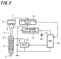
- FIG. 2 illustrates a circuit configuration for controlling a signal based on the value of the detected pen pressure transmitted from the position detecting coil 3.
- the core body 2 has the pen tip 1 at one end thereof so as to penetrate through the magnetic core 4 around which the conductive line as the position detecting coil 3 is wound, the conductive elastic member 5 at the other end of the core body 2, and the dielectric 6 having the electrode 7 and lead electrode 8 that is placed in the vicinity of the conductive elastic member 5.
- a resonant capacitor 11 are arranged in parallel with and connected to the position detecting coil 3.
- a switch 12 is connected to the both ends of the resonant capacitor 11 and is located therebetween.
- One end of the position detecting coil 3 is connected to a storage battery 14 via a voltage detecting circuit 13.
- the lead lines respectively extending from the electrode 7 and the lead electrode 8 are connected to a pen pressure detecting circuit 15, where the change in the capacitance value between the electrode 7 and the lead electrode 8 is detected.
- the change in the capacitance value obtained is detected as a predetermined value of the pen pressure applied by pressing the core body 2 against a digitizer.
- the resulting value of the pen pressure is supplied to a Central Processing Unit (CPU) 16.
- CPU Central Processing Unit
- a signal generated from the CPU 16 is supplied to the switch 12, which is switched on or off to transmit a desirable signal including the value of the pen pressure.
- Power charged in the storage battery 14 is supplied to the CPU 16 as driving power and is also supplied to components of the position indicator.
- the driving power is supplied to the position indicator of this embodiment via the position detecting coil 3 without power supply via a fixed line or a dry battery, thereby providing a position indicator that has excellent properties and is easy to be handled.
- This power supply also enables the position indicator of the embodiment to carry out more powerful transmission.
- a variable capacitance utilized as a pen pressure detector has a simple configuration, only including the following two components; that is, the core body 2 having the dome shaped conductive elastic member 5 located at the other end thereof, and the flat dielectric 6 having the electrode 7 on the first surface and the lead electrode 8 on the second surface thereof.
- the conductive elastic member 5 include silicon conductive rubber and pressure sensitive conductive rubber.
- a soft magnetic metal powder is allowed to mix with an organic resin binder, and the resulting composition is then formed, for example, by injection molding to produce the magnetic core 4.
- the material used is easier to form than the related-art soft magnetic metal.
- the thus formed magnetic core 4 exhibits excellent shock resistance in comparison to that made of the related-art soft magnetic metal, probability of damaging the core, around which the resonant coil for the position indicator is wound, may be lowered.
- the position indicator of the embodiment can thus be simply configured without having a buffer material around the core, and the shaft diameter of the position indicator can be reduced.
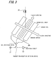
- FIG. 3 is a schematic configuration illustrating a coordinate input device provided with a cordless position indicator 20 of an embodiment of the invention.
- the coordinate input device employs an electromagnetic transmission-reception system and hence a plurality of sensor coil groups is placed on the coordinate input device in parallel with X-axis and Y-axis directions.
- An example of the current caused to flow in the sensor coil in transmission includes a high-frequency signal.
- a suitable high-frequency signal generator 21 is employed to generate the high-frequency signal.
- the coordinate input device further includes a coil switching device selecting each of the sensor coils for transmitting the high-frequency signal or receiving the signal.
- the coordinate input device still further includes a transmission-reception switching device for switching a transmission or reception state of each sensor coil.
- the coil switching device and the transmission-reception switching device may either be provided independently or in combination.
- the received signal is sent to a signal analyzing unit (not shown) via the receiving circuit 22, thereby computing a coordinate of the position indicator 20.
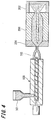
- FIG. 4 is a schematic configuration illustrating a configuration of a device used for forming the magnetic core 4 by injection molding.
- the composition obtained by mixing the soft magnetic metal powder in the binder such as an organic resin is injected from a hopper 101 to an injector 100.
- the injector 100 includes a heat source that melts the injected composition, and the obtained composition is then injected from an injecting nozzle 102 into a mold 200.
- the mold 200 is formed so as to correspond along an inner surface of the outer housing 10. One end of the mold 200 is connected to the injection nozzle 102 via a connecting unit 201 while the other end of a discharging unit 202 having a void into which part of the melted composition injected is discharged. The melted composition injected from the injecting nozzle 102 is filled in the mold 200 and part of the composition injected is discharged in the discharging unit 202.
- the aforementioned soft magnetic metal powder includes 25 to 65 vol% of the flat soft magnetic metal powder employing Fe as a master alloy.
- the core made of this composition exhibits excellent strength and shock resistance so that the core may not easily be broken. Since the composition made of the soft magnetic metal powder is solidified using a resin binder, the magnetic permeability of the composition is significantly lowered. However, the magnetic permeability of the composition can be improved by causing the flat soft magnetic metal powder to align in a predetermined direction using the aforementioned injection compression molding device.
- the formed magnetic core 4 is solidified with the soft magnetic metal powder thereof being aligned approximately in a predetermined direction, thereby obtaining a product having excellent properties as a magnetic core. Further, since the shape of the magnetic core 4 corresponds approximately to a shape of the inner surface of the outer housing 10, the tip of the magnetic core 4 can be located closely to the pen tip 1 of the position indicator of the embodiment. Moreover, since the magnetic field generated from the detectors can quickly be detected, accuracy in the position detection can also be improved.
- FIG. 5 is an external view illustrating the magnetic core 4 formed as described above.
Landscapes
- Engineering & Computer Science (AREA)
- Physics & Mathematics (AREA)
- General Physics & Mathematics (AREA)
- Power Engineering (AREA)
- General Engineering & Computer Science (AREA)
- Theoretical Computer Science (AREA)
- Human Computer Interaction (AREA)
- Dispersion Chemistry (AREA)
- Electromagnetism (AREA)
- Chemical & Material Sciences (AREA)
- Spectroscopy & Molecular Physics (AREA)
- Manufacturing & Machinery (AREA)
- Measurement Of Length, Angles, Or The Like Using Electric Or Magnetic Means (AREA)
- Soft Magnetic Materials (AREA)
- Position Input By Displaying (AREA)
- Coils Or Transformers For Communication (AREA)
- Powder Metallurgy (AREA)
- Injection Moulding Of Plastics Or The Like (AREA)
- Switches That Are Operated By Magnetic Or Electric Fields (AREA)
Applications Claiming Priority (1)
| Application Number | Priority Date | Filing Date | Title |
|---|---|---|---|
| JP2007016648A JP4950679B2 (ja) | 2007-01-26 | 2007-01-26 | 位置指示装置 |
Publications (3)
| Publication Number | Publication Date |
|---|---|
| EP1950772A2 EP1950772A2 (en) | 2008-07-30 |
| EP1950772A3 EP1950772A3 (en) | 2010-12-08 |
| EP1950772B1 true EP1950772B1 (en) | 2016-10-26 |
Family
ID=39323817
Family Applications (1)
| Application Number | Title | Priority Date | Filing Date |
|---|---|---|---|
| EP08100725.4A Ceased EP1950772B1 (en) | 2007-01-26 | 2008-01-22 | Magnetic core and position indicator |
Country Status (5)
| Country | Link |
|---|---|
| US (1) | US8674967B2 (https=) |
| EP (1) | EP1950772B1 (https=) |
| JP (1) | JP4950679B2 (https=) |
| CN (1) | CN101251775A (https=) |
| TW (1) | TWI426441B (https=) |
Cited By (1)
| Publication number | Priority date | Publication date | Assignee | Title |
|---|---|---|---|---|
| US20230367404A1 (en) * | 2022-05-10 | 2023-11-16 | Daiyun Chen | Electromagnetic pen with a front end having magnetic conductivity |
Families Citing this family (37)
| Publication number | Priority date | Publication date | Assignee | Title |
|---|---|---|---|---|
| JP5109171B2 (ja) * | 2007-09-18 | 2012-12-26 | 株式会社ワコム | 位置指示器、位置入力装置及びコンピュータシステム |
| JP4683142B2 (ja) | 2008-07-17 | 2011-05-11 | ブラザー工業株式会社 | 画像形成装置 |
| JP5206343B2 (ja) * | 2008-11-13 | 2013-06-12 | 株式会社ワコム | 位置指示器 |
| JP5358834B2 (ja) * | 2009-02-17 | 2013-12-04 | 株式会社ワコム | 位置指示器及び入力装置 |
| JP5483430B2 (ja) * | 2010-03-31 | 2014-05-07 | 株式会社ワコム | 可変容量コンデンサおよび位置指示器 |
| JP5569939B2 (ja) * | 2010-09-27 | 2014-08-13 | 株式会社ワコム | 可変容量コンデンサ、位置指示器および入力装置 |
| US9122322B2 (en) | 2011-03-17 | 2015-09-01 | Microsoft Technology Licensing, Llc | Interacting tips for a digitizer stylus |
| CN102236435B (zh) * | 2011-04-13 | 2016-08-03 | 北京南昊科技股份有限公司 | 一种新的电磁笔结构 |
| CN102253733B (zh) * | 2011-04-13 | 2016-08-03 | 北京南昊科技股份有限公司 | 一种电磁笔外形结构 |
| US8878823B1 (en) * | 2011-07-27 | 2014-11-04 | Cypress Semiconductor Corporation | Dynamic shield electrode of a stylus |
| TWI450135B (zh) * | 2011-12-06 | 2014-08-21 | Wistron Corp | 電磁式觸控筆及其電腦設備 |
| JP5892595B2 (ja) * | 2012-02-06 | 2016-03-23 | 株式会社ワコム | 位置指示器 |
| KR20130107886A (ko) * | 2012-03-23 | 2013-10-02 | 삼성전기주식회사 | 디지타이저 |
| KR20140018017A (ko) * | 2012-08-03 | 2014-02-12 | 삼성전기주식회사 | 디지타이저 |
| JP2014035626A (ja) * | 2012-08-08 | 2014-02-24 | Wacom Co Ltd | 電子回路及び位置指示器 |
| KR20140024741A (ko) * | 2012-08-21 | 2014-03-03 | 삼성전기주식회사 | 디지타이저 |
| JP5400237B2 (ja) * | 2013-03-18 | 2014-01-29 | 株式会社ワコム | 位置指示器、可変容量コンデンサ及び入力装置 |
| JP5667708B2 (ja) | 2013-06-20 | 2015-02-12 | 株式会社ワコム | 位置指示器及び位置指示器の芯体 |
| JP5647715B1 (ja) * | 2013-06-27 | 2015-01-07 | 株式会社ワコム | 位置指示器 |
| JP5639703B2 (ja) * | 2013-10-23 | 2014-12-10 | 株式会社ワコム | 位置指示器、可変容量コンデンサ及び入力装置 |
| WO2015082438A1 (en) * | 2013-12-02 | 2015-06-11 | Dsm Ip Assets B.V. | Rod core inductors |
| WO2015082440A1 (en) * | 2013-12-02 | 2015-06-11 | Dsm Ip Assets B.V. | Rod core inductors |
| JP6159874B2 (ja) * | 2014-03-28 | 2017-07-05 | ニューコムテクノ株式会社 | 電子ペン |
| KR20160092360A (ko) * | 2015-01-27 | 2016-08-04 | 삼성전자주식회사 | 스타일러스 펜 및 터치 패널 |
| JP6495730B2 (ja) * | 2015-04-30 | 2019-04-03 | ホシデン株式会社 | 二次コイルモジュール |
| CN105607766B (zh) * | 2016-03-15 | 2017-12-22 | 深圳市华鼎星科技有限公司 | 一种可变电容式压力传感器和真笔迹触控笔 |
| US9841828B2 (en) * | 2016-04-20 | 2017-12-12 | Microsoft Technology Licensing, Llc | Pressure sensitive stylus |
| TWI736580B (zh) * | 2016-04-22 | 2021-08-21 | 日商和冠股份有限公司 | 電子筆及電子筆本體部 |
| WO2018197052A1 (de) * | 2017-04-29 | 2018-11-01 | Luitpold Greiner | Taktiles display mit magnetisch bistabilen axialsymmetrischen linear-aktuator mit polkontur und schaltmatrix und optisch-taktile sehhilfe hiermit |
| DE102017216772A1 (de) | 2017-09-21 | 2019-03-21 | Continental Automotive Gmbh | Plattenkondensator |
| US10996078B2 (en) * | 2017-11-10 | 2021-05-04 | Honeywell International Inc. | C-shaped cylindrical core for linear variable differential transformer (LVDT) probes |
| TWI709020B (zh) * | 2018-03-30 | 2020-11-01 | 日商京瓷股份有限公司 | 電感用芯、電子筆用芯體部、電子筆及輸入裝置 |
| TWI709021B (zh) * | 2018-03-30 | 2020-11-01 | 日商京瓷股份有限公司 | 電感用芯、電子筆用芯體部、電子筆及輸入裝置 |
| TWI709019B (zh) * | 2018-03-30 | 2020-11-01 | 日商京瓷股份有限公司 | 電感用芯、電子筆用芯體部、電子筆及輸入裝置 |
| KR102833078B1 (ko) * | 2021-01-14 | 2025-07-14 | 삼성전자 주식회사 | 디지털 펜 및 이를 갖는 휴대 전자 장치 |
| KR20240065507A (ko) | 2022-10-31 | 2024-05-14 | 삼성디스플레이 주식회사 | 펜 및 그것을 포함하는 표시 장치 |
| KR20250064721A (ko) | 2023-11-02 | 2025-05-12 | 삼성디스플레이 주식회사 | 전자 장치 |
Family Cites Families (22)
| Publication number | Priority date | Publication date | Assignee | Title |
|---|---|---|---|---|
| DE3789922T2 (de) * | 1986-07-23 | 1995-01-05 | Wacom Co Ltd | Koordinateneingabesystem. |
| JP3150685B2 (ja) * | 1990-08-06 | 2001-03-26 | 株式会社ワコム | 可変容量コンデンサ |
| US6468678B1 (en) * | 1994-11-17 | 2002-10-22 | 3M Innovative Properties Company | Conformable magnetic articles for use with traffic bearing surfaces methods of making same systems including same and methods of use |
| JP2717774B2 (ja) * | 1995-01-13 | 1998-02-25 | 株式会社ワコム | 感圧素子及び感圧機能付スタイラスペン |
| JP2767098B2 (ja) * | 1995-06-06 | 1998-06-18 | 株式会社ワコム | 位置指示ユニット及びスタイラスペン |
| JP2000013415A (ja) | 1998-06-25 | 2000-01-14 | Matsushita Electric Works Ltd | 遠隔監視制御システム |
| JP2001068324A (ja) * | 1999-08-30 | 2001-03-16 | Hitachi Ferrite Electronics Ltd | 粉末成形磁芯 |
| JP4376425B2 (ja) | 2000-05-08 | 2009-12-02 | 株式会社ワコム | 可変容量コンデンサ及び位置指示器 |
| DE10024824A1 (de) * | 2000-05-19 | 2001-11-29 | Vacuumschmelze Gmbh | Induktives Bauelement und Verfahren zu seiner Herstellung |
| JP2002022938A (ja) | 2000-07-10 | 2002-01-23 | Sumitomo Osaka Cement Co Ltd | 波長選択フィルタ及び波長制御モジュール |
| JP3914421B2 (ja) * | 2000-12-13 | 2007-05-16 | 株式会社ワコム | ペン型座標指示器 |
| DE10128004A1 (de) * | 2001-06-08 | 2002-12-19 | Vacuumschmelze Gmbh | Induktives Bauelement und Verfahren zu seiner Herstellung |
| JP2002028064A (ja) | 2001-06-20 | 2002-01-29 | Shiyuugo Miyagawa | 傘の水切り機 |
| US6937231B2 (en) * | 2001-09-21 | 2005-08-30 | Wacom Co., Ltd. | Pen-shaped coordinate pointing device |
| US6727439B2 (en) * | 2002-01-28 | 2004-04-27 | Aiptek International Inc. | Pressure sensitive pen |
| US20030157472A1 (en) * | 2002-02-15 | 2003-08-21 | Avery Dennison Corporation | Stylus actuated write/erase binders |
| JP2004071845A (ja) * | 2002-08-07 | 2004-03-04 | Mate Co Ltd | 軟磁性樹脂成型品及びその成型方法 |
| US20040144575A1 (en) * | 2003-01-27 | 2004-07-29 | Yitzhak Zloter | Digitizer pen for writing on reusable paper |
| KR100545849B1 (ko) * | 2003-08-06 | 2006-01-24 | 주식회사 아모텍 | 철계 비정질 금속 분말의 제조방법 및 이를 이용한 연자성코어의 제조방법 |
| JP2005149140A (ja) * | 2003-11-14 | 2005-06-09 | Wacom Co Ltd | 位置検出装置及び位置指示器 |
| US8723842B2 (en) * | 2005-03-01 | 2014-05-13 | Wacom Co., Ltd | Position pointing device and hand-held electronic appliance |
| JP2007016648A (ja) | 2005-07-06 | 2007-01-25 | Mitsubishi Electric Corp | 燃料噴射装置 |
-
2007
- 2007-01-26 JP JP2007016648A patent/JP4950679B2/ja active Active
-
2008
- 2008-01-21 TW TW097102144A patent/TWI426441B/zh not_active IP Right Cessation
- 2008-01-22 EP EP08100725.4A patent/EP1950772B1/en not_active Ceased
- 2008-01-23 CN CNA2008100039684A patent/CN101251775A/zh active Pending
- 2008-01-23 US US12/018,512 patent/US8674967B2/en active Active
Non-Patent Citations (1)
| Title |
|---|
| None * |
Cited By (2)
| Publication number | Priority date | Publication date | Assignee | Title |
|---|---|---|---|---|
| US20230367404A1 (en) * | 2022-05-10 | 2023-11-16 | Daiyun Chen | Electromagnetic pen with a front end having magnetic conductivity |
| US11853490B2 (en) * | 2022-05-10 | 2023-12-26 | Daiyun Chen | Electromagnetic pen with a front end having magnetic conductivity |
Also Published As
| Publication number | Publication date |
|---|---|
| CN101251775A (zh) | 2008-08-27 |
| US8674967B2 (en) | 2014-03-18 |
| EP1950772A2 (en) | 2008-07-30 |
| JP4950679B2 (ja) | 2012-06-13 |
| JP2008186071A (ja) | 2008-08-14 |
| TWI426441B (zh) | 2014-02-11 |
| EP1950772A3 (en) | 2010-12-08 |
| TW200907774A (en) | 2009-02-16 |
| US20080180092A1 (en) | 2008-07-31 |
Similar Documents
| Publication | Publication Date | Title |
|---|---|---|
| EP1950772B1 (en) | Magnetic core and position indicator | |
| CN101430616B (zh) | 位置指示器及坐标输入装置 | |
| US10768723B2 (en) | Electronic pen and electronic pen main body | |
| JP5689587B2 (ja) | 電力伝送装置 | |
| CN201590054U (zh) | 位置指示器、电路部件及输入装置 | |
| US11216087B2 (en) | Position detecting device and position indicator thereof | |
| CN105437989B (zh) | 用于测量电池内部状态的传感器系统 | |
| TWI736580B (zh) | 電子筆及電子筆本體部 | |
| CN105929985B (zh) | 带射频收发传输功能的真笔迹触控笔和触控装置 | |
| EP2887190A1 (en) | Capacitive sensor electrode | |
| US6831457B2 (en) | Two-dimensional magnetic sensor including magneto-impedance sensor elements | |
| CN102422502A (zh) | 感应充电装置 | |
| CN108521836B (zh) | 无线功率传输设备和方法 | |
| TW200917101A (en) | Position indicator, variable capacitor, position input device and computer system | |
| CN107430449A (zh) | 位置指示器 | |
| US10495486B2 (en) | Inductive touch input | |
| KR20180027507A (ko) | 위치 지시기 | |
| CN108987834A (zh) | 监测电池单元的内部压力的设备和装置及电池管理系统 | |
| CN110261001A (zh) | 电缆中间接头温度测量系统 | |
| CN103999283B (zh) | 用于传输来自电池单元的信息的装置和方法以及电池单元 | |
| US20150288361A1 (en) | Capacitive Sensor Device And Method For Operating A Capacitive Sensor Device | |
| CN111984134B (zh) | 位置指示器及坐标输入装置 | |
| US20240152219A1 (en) | Electronic pen | |
| CN102412629A (zh) | 蓄能式无线传感器 | |
| EP4287224A1 (en) | Wireless charging apparatus and transportation means comprising same |
Legal Events
| Date | Code | Title | Description |
|---|---|---|---|
| PUAI | Public reference made under article 153(3) epc to a published international application that has entered the european phase |
Free format text: ORIGINAL CODE: 0009012 |
|
| AK | Designated contracting states |
Kind code of ref document: A2 Designated state(s): AT BE BG CH CY CZ DE DK EE ES FI FR GB GR HR HU IE IS IT LI LT LU LV MC MT NL NO PL PT RO SE SI SK TR |
|
| AX | Request for extension of the european patent |
Extension state: AL BA MK RS |
|
| PUAL | Search report despatched |
Free format text: ORIGINAL CODE: 0009013 |
|
| AK | Designated contracting states |
Kind code of ref document: A3 Designated state(s): AT BE BG CH CY CZ DE DK EE ES FI FR GB GR HR HU IE IS IT LI LT LU LV MC MT NL NO PL PT RO SE SI SK TR |
|
| AX | Request for extension of the european patent |
Extension state: AL BA MK RS |
|
| PUAF | Information related to the publication of a search report (a3 document) modified or deleted |
Free format text: ORIGINAL CODE: 0009199SEPU |
|
| D17D | Deferred search report published (deleted) | ||
| PUAL | Search report despatched |
Free format text: ORIGINAL CODE: 0009013 |
|
| RIC1 | Information provided on ipc code assigned before grant |
Ipc: H01G 5/16 20060101ALI20101028BHEP Ipc: G06F 3/03 20060101ALI20101028BHEP Ipc: H01F 3/08 20060101AFI20080508BHEP Ipc: H01F 41/02 20060101ALI20101028BHEP Ipc: H01F 1/26 20060101ALI20101028BHEP Ipc: G01D 5/22 20060101ALI20101028BHEP Ipc: G06F 3/033 20060101ALI20101028BHEP |
|
| AK | Designated contracting states |
Kind code of ref document: A3 Designated state(s): AT BE BG CH CY CZ DE DK EE ES FI FR GB GR HR HU IE IS IT LI LT LU LV MC MT NL NO PL PT RO SE SI SK TR |
|
| AX | Request for extension of the european patent |
Extension state: AL BA MK RS |
|
| 17P | Request for examination filed |
Effective date: 20110608 |
|
| AKX | Designation fees paid |
Designated state(s): DE GB |
|
| 17Q | First examination report despatched |
Effective date: 20150922 |
|
| REG | Reference to a national code |
Ref country code: DE Ref legal event code: R079 Ref document number: 602008047000 Country of ref document: DE Free format text: PREVIOUS MAIN CLASS: H01F0003080000 Ipc: G01D0005200000 |
|
| GRAP | Despatch of communication of intention to grant a patent |
Free format text: ORIGINAL CODE: EPIDOSNIGR1 |
|
| RIC1 | Information provided on ipc code assigned before grant |
Ipc: H01F 3/08 20060101ALI20160602BHEP Ipc: G06F 3/046 20060101ALI20160602BHEP Ipc: H01F 41/02 20060101ALI20160602BHEP Ipc: G01D 5/24 20060101ALI20160602BHEP Ipc: H01F 1/26 20060101ALI20160602BHEP Ipc: H01G 5/16 20060101ALI20160602BHEP Ipc: G01D 5/20 20060101AFI20160602BHEP Ipc: G01D 5/241 20060101ALI20160602BHEP Ipc: G06F 3/0354 20130101ALI20160602BHEP Ipc: H01F 17/04 20060101ALI20160602BHEP |
|
| INTG | Intention to grant announced |
Effective date: 20160617 |
|
| GRAS | Grant fee paid |
Free format text: ORIGINAL CODE: EPIDOSNIGR3 |
|
| GRAA | (expected) grant |
Free format text: ORIGINAL CODE: 0009210 |
|
| AK | Designated contracting states |
Kind code of ref document: B1 Designated state(s): DE GB |
|
| REG | Reference to a national code |
Ref country code: GB Ref legal event code: FG4D |
|
| REG | Reference to a national code |
Ref country code: DE Ref legal event code: R096 Ref document number: 602008047000 Country of ref document: DE |
|
| PGFP | Annual fee paid to national office [announced via postgrant information from national office to epo] |
Ref country code: DE Payment date: 20170120 Year of fee payment: 10 |
|
| PGFP | Annual fee paid to national office [announced via postgrant information from national office to epo] |
Ref country code: GB Payment date: 20170119 Year of fee payment: 10 |
|
| REG | Reference to a national code |
Ref country code: DE Ref legal event code: R097 Ref document number: 602008047000 Country of ref document: DE |
|
| PLBE | No opposition filed within time limit |
Free format text: ORIGINAL CODE: 0009261 |
|
| STAA | Information on the status of an ep patent application or granted ep patent |
Free format text: STATUS: NO OPPOSITION FILED WITHIN TIME LIMIT |
|
| 26N | No opposition filed |
Effective date: 20170727 |
|
| REG | Reference to a national code |
Ref country code: DE Ref legal event code: R119 Ref document number: 602008047000 Country of ref document: DE |
|
| GBPC | Gb: european patent ceased through non-payment of renewal fee |
Effective date: 20180122 |
|
| PG25 | Lapsed in a contracting state [announced via postgrant information from national office to epo] |
Ref country code: DE Free format text: LAPSE BECAUSE OF NON-PAYMENT OF DUE FEES Effective date: 20180801 |
|
| PG25 | Lapsed in a contracting state [announced via postgrant information from national office to epo] |
Ref country code: GB Free format text: LAPSE BECAUSE OF NON-PAYMENT OF DUE FEES Effective date: 20180122 |