EP1950347B1 - Stützplatte für flexible Befestigungen von Eisenbahnschienen - Google Patents
Stützplatte für flexible Befestigungen von Eisenbahnschienen Download PDFInfo
- Publication number
- EP1950347B1 EP1950347B1 EP08380021.9A EP08380021A EP1950347B1 EP 1950347 B1 EP1950347 B1 EP 1950347B1 EP 08380021 A EP08380021 A EP 08380021A EP 1950347 B1 EP1950347 B1 EP 1950347B1
- Authority
- EP
- European Patent Office
- Prior art keywords
- rail
- support plate
- rail splice
- portions
- central span
- Prior art date
- Legal status (The legal status is an assumption and is not a legal conclusion. Google has not performed a legal analysis and makes no representation as to the accuracy of the status listed.)
- Revoked
Links
Images


Classifications
-
- E—FIXED CONSTRUCTIONS
- E01—CONSTRUCTION OF ROADS, RAILWAYS, OR BRIDGES
- E01B—PERMANENT WAY; PERMANENT-WAY TOOLS; MACHINES FOR MAKING RAILWAYS OF ALL KINDS
- E01B9/00—Fastening rails on sleepers, or the like
- E01B9/38—Indirect fastening of rails by using tie-plates or chairs; Fastening of rails on the tie-plates or in the chairs
- E01B9/40—Tie-plates for flat-bottom rails
-
- E—FIXED CONSTRUCTIONS
- E01—CONSTRUCTION OF ROADS, RAILWAYS, OR BRIDGES
- E01B—PERMANENT WAY; PERMANENT-WAY TOOLS; MACHINES FOR MAKING RAILWAYS OF ALL KINDS
- E01B9/00—Fastening rails on sleepers, or the like
- E01B9/38—Indirect fastening of rails by using tie-plates or chairs; Fastening of rails on the tie-plates or in the chairs
- E01B9/44—Fastening the rail on the tie-plate
- E01B9/46—Fastening the rail on the tie-plate by clamps
- E01B9/48—Fastening the rail on the tie-plate by clamps by resilient steel clips
- E01B9/483—Fastening the rail on the tie-plate by clamps by resilient steel clips the clip being a shaped bar
-
- E—FIXED CONSTRUCTIONS
- E01—CONSTRUCTION OF ROADS, RAILWAYS, OR BRIDGES
- E01B—PERMANENT WAY; PERMANENT-WAY TOOLS; MACHINES FOR MAKING RAILWAYS OF ALL KINDS
- E01B9/00—Fastening rails on sleepers, or the like
- E01B9/68—Pads or the like, e.g. of wood, rubber, placed under the rail, tie-plate, or chair
- E01B9/685—Pads or the like, e.g. of wood, rubber, placed under the rail, tie-plate, or chair characterised by their shape
Definitions
- the present invention relates to a support plate for flexible fastening of railway rails that applies to the railway industry field, allowing an elastic and flexible fastening for the absorption of deformations produced in the rail, by means of a single piece, with the resulting savings in the production costs and simplicity of installation.
- these means comprise different elements, among which is found at least one guide plate that guides the rail, a rail splice, also referred to as elastic fastening clip or band, a grounding insulating plate that is situated under the rail, at least one rail screw and in some cases a bearing plate.
- each one of these elements is an independent piece, which requires a linking or joining therebetween, each one of them having a specific function.
- the elastic character of this type of fastener wherein a means of sliding or elastic securing is required, i.e. which secures, but does not immobilize, the rail at its vertical axis, is determined with the object of allowing an absorption of the deformations produced in the rail, for example, as a consequence of the stress that is produced during the circulation of the machines and wagons and prevents the thermal expansions, at the same time that it fulfils its fastening function.
- Spanish patent no. ES 285 328 and in European patent no. EP 0295685 disclose devices for the securing of railway rails on the railway track, which comprise, for each fastening point of a rail, two guide plates that are situated on both sides of the rail, each one of which is secured to the bearing area or rail-bearer by means of an elastic rail splice that treads on the rail and that is fastened by a rail screw, an insulating plate being situated under the rail.
- the guide plate is configured to house the external part of the rail splice and make contact in the lateral area of the rail flange.
- the preform of the rail-bearer must also have the track or negative corresponding to the guide plate, with the object that the guide plate remains immobile in its service position, these being the drawbacks entailed by not having a bearing plate, which serves to achieve the incline of the rail and allows the installation of the rail on any surface.
- metal bearing plates such as those disclosed in different technical standards, such as, for example, in the American standard corresponding to the AREMA organization, American Railway Engineering and Maintenance-of-Way Association, and in the Brazilian standard.
- These bearing plates have a specific incline, which can be seen in a variation of thickness of the plate, wherein the lower bearing area is situated in contact with a rail-bearer, remaining in horizontal position while the upper surface of the bearing plate has a specific angle with the lower surface, i.e. both surfaces or sides of the plate are not parallel, with the object of guiding the loads towards the rail, or rather towards the rail gage or middle area of the railway.
- United States patent no. US 3,439,874 discloses a layout for the securing of rails which, besides the elements disclosed in the previously mentioned patents, comprises bearing plates, preferably of a laminated metal material.
- Said bearing plate consists of a flat piece that comprises two ridges parallel to the rail that are configured to make contact with the rail and position it, at the same time serving as support and position limiter for the elastic rail splice.
- bearing plate does not have an inclined surface provided for the rail to have the mandatory incline. Additionally, said bearing plate does not have adequate means for the containment and elastic fastening of the rail splice in its working position, which could even pop out of its position.
- This bearing plate is a completely flat piece with parallel upper and undersides, comprising two ridges, an outer ridge for the rail splice and an inner ridge for the rail, with respect to the axis of the rail screw, which makes the contact with the rail splice precise, not adapting to an optimal fastening thereof.
- the bearing area of the plate is flat and does not allow the housing of foreign elements, such as, for example, a stone, during its installation, which produces undesired alterations in the horizontal position or even the breakage of the bearing plate, above all when it is in a load situation, for example during the passing of a train, i.e. when it has a usage load.
- each fastening point comprises a guide plate, such as, for example, those disclosed in Spanish patent no. ES 2 160 529 and in European patent no. 0767274 .
- the main drawback of these fastenings is that they do not have a bearing plate.
- These devices comprise a flexed guide plate configured to be housed in rail shoes that must have a complementary space on the upper surface of the pre-fabricated rail-bearers, said guide plate remaining adjacent to the rail flange, with the object of immobilizing it in its position and absorbing the lateral thrust of the train wheels on their passage along the track, as well as the deformations previously mentioned.
- the international patent application WO03/012204 A1 discloses a rail vibration isolator for improving efficiency of vibration isolation, laying the rail conveniently, and wherein the replacement of a vibration isolating pad is simple and the maintenance of the railroad line is convenient.
- This invention relates to a support plate for flexible fastenings of railway rails which has a single-piece configuration and comprises means to guide and support a rail on a bearing area, said support piece comprising a plurality of contact slits and rail shoes configured to house and fasten an attaching flange of said rail.
- the support plate proposed by the invention allows an elastic and flexible fastening, by means of a sliding securing, i.e. which secures but does not immobilize the rail at its vertical axis, with the object of allowing an absorption of the deformations produced in the rail, for example as a consequence of the thermal expansions or lateral thrust of the train wheels on their passage along the track, all of this without failing in its fastening function.
- the invention relates to a support plate, which serves as a means of elastic fastening of railway rails, being configured to attach to any bearing area, i.e. to smooth cement or concrete surfaces, such as wooden and concrete rail-bearers.
- the support plate has a symmetric single-piece configuration with respect to a half-imaginary axis perpendicular to the rail.
- the support plate comprises means of guiding a rail, a function that was done by the guide plate in the fastening devices used until now, at the same time comprising means of supporting, i.e. serve as support for said rail, a function that until now was done by means of another different piece, which was the bearing plate.
- the support plate comprises at least two rail shoes on each side of the central span, which are two slots configured to house and receive, serving as support, curved areas that has the rail splice in an area opposite the contact area of said rail splice with the rail flange.
- the support plate proposed by the invention it is possible to dispense with the guide plates currently used, which have a lower protuberance for the housing and support of the rail splice, requiring that the bearing area or the bearing plate to be used have a shape operatively adapted to receive the settlement of said lower protuberance.
- the elasticity to the fastening of the rail is increased which results in an increase in the feeling of comfort perceived by the passenger, the fastening providing a greater degree of cushioning, which results in a greater protection of the railway, considering its use in continuous tracks, unlike the bearing plates used until now, which did not allow for their installation in any span.
- the support plate comprises, with the object of guiding a flat, central and lowered span along the rail, an upper part, which is configured to be in contact and support a rail flange, said central span having an appropriate incline for the seating of said rail.
- the support plate comprises at least two through-holes, such as two cylindrical slits, one through-hole and one cylindrical slit situated on each side of the central span between the contact slits.
- Each cylindrical slit is aligned according to a perpendicular direction to the rail with at least one through-hole, each one of said holes being configured to house a rail screw to secure the support plate to the rail splice or elastic clip.
- Each cylindrical slit is flanked, according to a direction parallel to the rail, preferably by two contact slits, configured to be in contact with a rail splice or elastic clip, which at the same time is configured to make contact with the rail flange and immobilize it, which means that the contact slits have the shape of the rail splice in said contact area.
- the support plate in an underside, where the through-holes comprise a polygonal area, preferably hexagonal, is configured to house the hexagonal head of the rail screw, allowing for an optimal immobilization thereof.
- the support plate comprises a plurality of securing holes, preferably six spaced out evenly in each outer area, i.e. in the areas furthest from the central span, said securing holes being configured to allow an operator to secure the support plate to any span, in accordance with the type of bearing area wherein it is intended to be secured, allowing for the avoidance of deformations when the support plate is fitted, for example, to a wooden bearing area.
- the securing holes are aligned according to a direction parallel to the rail.
- the central span is configured to house an elastic insulating base plate configured, at the same time, to be in contact with the rail flange, with the object of avoiding breakages of the support plate.
- the central span can comprise, at ends perpendicular to the rail, two cross-sectional studs configured to immobilize the insulating base plate in its position on the central span, allowing for the resistance of the stress produced in the direction of the rail, above all at the points of braking and start-up of a train, avoiding that the insulating base plate is blown out of its service position.
- the underside of the support plate comprises a plurality of ridges, preferably perpendicular and covering the whole surface of said underside, with the object of lightening the piece, conserving its mechanical resistance, allowing for the housing of any foreign object between said ridges, like for example stones, which could be found on the bearing area at the time of installation of the support plates.
- the bearing area can comprise a plurality of stubs, situated on the upper side and preferably two to each side of the central span, which are configured to allow for the stacking of the support plates, with the resulting saving of time and space during the operations of transport and storage thereof.
- the support plate comprises, on each side of the central span, at least two rail splice alignment ridges on the upper side, which flank the contact slits according to an alignment thereof, i.e. according to a direction parallel to the rail.
- Each alignment ridge is bearing area a complementary ridge, configured to be used in the subassembly, the complementary ridges remaining on the outer side of each alignment ridge, with respect to the central span of the support plate, the rail splice or elastic clip remaining immobilized in an optimal position.
- the support plate of the invention is made of a plastic material, with the resulting savings in its manufacture by injection, being lighter and easier to transport and store.
- the support plate is made of polyamide with fibre-glass, even being able to be self-extinguishing VO.
- the support plate for flexible fastening of railway rails that the invention proposes constitutes an advance in the fastenings used until now, and resolves the problem previously stated in a completely satisfactory way, in the line of allowing an elastic and efficient fastening in only one piece, with the resulting economic savings and installation advantages.
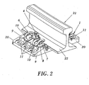
- a support plate (1) for flexible fastenings of railway rails that has a symmetric single-piece configuration with respect to a half-imaginary axis perpendicular to the rail (21), said support plate (1) comprising means of guiding and supporting a rail (21) on a bearing area (18), which can be a smooth cement or concrete surface, such as wooden and concrete rail-bearers, said support plate (1) comprising two contact slits (5) and two rail shoes (9) on each side of the central span (12), which are two slots configured to house and receive curved areas (10) that has a rail splice (6) in an area opposite that of contact of said rail splice (6) with a rail (21) flange (22).
- an upper part of the support plate (1) comprises a flat and lowered central span (12) that is configured to be in contact and support the rail (21) flange (22), said central span (12) having an appropriate incline for the seat of said rail (21).
- the support plate (1) comprises two through-holes (3) and two cylindrical slits (2), one through-hole (3) and one cylindrical slit (2) situated on each side of the central span (12) between two contact slits (5).
- Each cylindrical slit (2) is aligned according to a direction perpendicular to the rail (21) with the through-hole (3), said through-holes (3) being configured to house a rail screw (4) to secure the support plate (1) to a rail splice (6) or elastic clip.
- Each cylindrical slit (2) is flanked, according to a direction parallel to the rail (21), by two contact slits (5), configured to be in contact with a rail splice (6) or elastic clip, which at the same time is configured to make contact with the rail (21) flange (22) and immobilize it, for which reason the contact slits (5) have the shape of the rail splice (6) in said contact area.
- An underside (15) of the support plate (1) comprises a polygonal area (19), specifically of hexagonal configuration, in the through-holes (3), configured to house the head of a rail screw (4).
- the support plate (1) comprises six securing holes (11), spaced out evenly in each outer area (20) and aligned according to a direction parallel to the rail (21), said securing holes (11) being configured to allow the securing of the support plate (1) to any type of bearing area (18).
- the central span (12) is configured to house an elastic insulating base plate configured at the same time to be in contact with the rail (21) flange (22), with the object of avoiding breakages of the support plate (1).
- the central span (12) comprises, at perpendicular ends of the rail (21), two cross-sectional studs (14) configured to immobilize said insulating base plate (13) in its position on the central span (12).
- the underside (15) of the support plate (1) comprises a plurality of ridges (16) that cover the entire surface of said lower part (15), as can be observed in figure 4 .
- the support plate (1) comprises four stubs (17), situated on the upper side, two being on each side of the central span (12), which are configured to allow for a stacking of the support plates (1).
- the support plate (1) comprises, on each side of the central span (12), two alignment ridges (7) of the rail splice (6) on the upper side, which flank the contact slits (5).
- Each alignment ridge (7) is bearing area a complementary ridge (8), configured to be used in the subassembly, the complementary ridges (8) remaining on the outer side of each alignment ridge (7), respect to the central span (12) of the support plate (1), the rail splice (6) remaining immobilized in an optimal position.
- the support plate (1) of the invention is made of polyamide with self-extinguishing VO fibre-glass.
Landscapes
- Engineering & Computer Science (AREA)
- Mechanical Engineering (AREA)
- Architecture (AREA)
- Civil Engineering (AREA)
- Structural Engineering (AREA)
- Connection Of Plates (AREA)
- Bridges Or Land Bridges (AREA)
Claims (10)
- Stützplatte mit einer Schienenlasche für die flexible Befestigung von Eisenbahnschienen (21), wobei die Stützplatte (1) umfasst:eine einteilige Konstruktion, umfassend eine obere Fläche;eine Vielzahl von Aufnahmeelementen, die sich von der oberen Fläche erheben;eine Vielzahl von Schienenschuhen (9), wobei jeder Schienenschuh (9) eine Nut aufweist, die in der Oberfläche ausgebildet ist; undwobei die Schienenlasche (6) eine Vielzahl von ersten Abschnitten und eine Vielzahl von zweiten Abschnitten umfasst, die einen gebogenen Bereich (10) aufweisen, wobei die ersten Abschnitte die zweiten Abschnitte beabstanden, jeder Schienenschuh (9) jeweils ein Ende der zweiten Abschnitte der Schienenlasche (6) aufnimmt und die Vielzahl der Aufnahmeelemente jeweils einen der ersten Abschnitte aufnehmen,dadurch gekennzeichnet, dass die Stützplatte (1) des Weiteren eine Vielzahl von Ausrichtungserhöhungen (7) für die Schienenlasche (6) an der oberen Fläche umfassen, wobei jede Ausrichtungserhöhung (7) eine Auflagefläche und eine Komplementärerhöhung (8) umfasst und wobei die einteilige Konstruktion durch Spritzguss gefertigt wird und aus Polyamid mit Glasfaser besteht.
- Stützplatte mit einer Schienenlasche nach Anspruch 1, wobei die Stützplatte (1) einen oberen Teil aufweist, der einen flachen und abgesenkten Mittelbereich (12) umfasst, der dazu eingerichtet ist, mit dem Flansch (22) einer Schiene (21) in Kontakt zu stehen und diesen zu stützen, wobei dieser Mittelbereich (12) eine Neigung für den Sitz der Schiene (21) aufweist.
- Stützplatte mit einer Schienenlasche nach einem der vorhergehenden Ansprüche, wobei die Stützplatte mindestens zwei Durchgangsbohrungen (3) aufweist, jeweils eine Durchgangsbohrung (3) auf jeder Seite des Mittelbereichs (12) zwischen den Aufnahmeelementen (5) angeordnet ist, die Durchgangsbohrungen (3) jeweils dazu eingerichtet sind, eine Schienenschraube (4) aufzunehmen, damit die Stützplatte an der Schienenlasche (6) befestigt werden kann.
- Stützplatte mit einer Schienenlasche nach Anspruch 3, wobei die Stützplatte eine Unterseite (15) umfasst, und die Durchgangsbohrungen (3) einen polygonalen Bereich (19) umfassen, der zum Aufnehmen eines Kopfes einer Schienenschraube (4) ausgebildet ist.
- Stützplatte mit einer Schienenlasche nach einem der vorhergehenden Ansprüche, wobei die Stützplatte in jedem Außenbereich (20) eine Vielzahl von Befestigungsbohrungen (11) aufweisen, die dazu eingerichtet sind, die Stützplatte an einer Auflagefläche (18) zu befestigen.
- Stützplatte mit einer Schienenlasche nach einem der Ansprüche 2 bis 5, wobei der Mittelbreich (12) zur Aufnahme einer elastischen, dämpfenden Grundplatte (13) eingerichtet ist, die dafür ausgelegt ist, mit dem Flansch (22) der Schiene (21) in Kontakt zu stehen.
- Stützplatte mit einer Schienenlasche nach Anspruch 6, wobei der Mittelbereich (12) zwei quer verlaufende Riegel (14) umfasst, die dazu eingerichtet sind, die elastische, dämpfende Grundplatte (13) zu immobilisieren.
- Stützplatte mit einer Schienenlasche nach einem der Ansprüche 4 bis 7, wobei die Unterseite (15) eine Vielzahl von Rippen (16) umfasst.
- Stützplatte mit einer Schienenlasche nach einem der Ansprüche 2 bis 8, wobei die Stützplatte eine Vielzahl von Stutzen (17) umfasst, die zum Stapeln der Stützplatten eingerichtet sind.
- Stützplatte mit einer Schienenlasche nach Anspruch 1, wobei jedes Aufnahmeelement eine Vertiefung umfasst, um zusammenwirkend den entsprechenden ersten Abschnitt der Schienenlasche aufzunehmen.
Applications Claiming Priority (1)
| Application Number | Priority Date | Filing Date | Title |
|---|---|---|---|
| ES200700170U ES1064713Y (es) | 2007-01-26 | 2007-01-26 | Placa de apoyo para sujeciones flexibles de railes ferroviarios |
Publications (3)
| Publication Number | Publication Date |
|---|---|
| EP1950347A2 EP1950347A2 (de) | 2008-07-30 |
| EP1950347A3 EP1950347A3 (de) | 2010-09-22 |
| EP1950347B1 true EP1950347B1 (de) | 2014-03-05 |
Family
ID=38325063
Family Applications (1)
| Application Number | Title | Priority Date | Filing Date |
|---|---|---|---|
| EP08380021.9A Revoked EP1950347B1 (de) | 2007-01-26 | 2008-01-28 | Stützplatte für flexible Befestigungen von Eisenbahnschienen |
Country Status (3)
| Country | Link |
|---|---|
| US (1) | US20080179419A1 (de) |
| EP (1) | EP1950347B1 (de) |
| ES (2) | ES1064713Y (de) |
Cited By (1)
| Publication number | Priority date | Publication date | Assignee | Title |
|---|---|---|---|---|
| RU2581340C1 (ru) * | 2014-09-23 | 2016-04-20 | Олег Николаевич ГОЛОВАЧ | Подрельсовая подкладка |
Families Citing this family (20)
| Publication number | Priority date | Publication date | Assignee | Title |
|---|---|---|---|---|
| DE202006009340U1 (de) * | 2006-06-14 | 2006-08-17 | Seifert, Dietrich | Vorrichtung zur Lagesicherung und Führung von Schienen |
| DE102007025708B4 (de) * | 2007-06-01 | 2009-06-18 | Schwihag Ag | Kraftschlüssige elastische Schienenbefestigung für Gleisanlagen |
| WO2010091725A1 (de) * | 2009-02-11 | 2010-08-19 | Vossloh-Werke Gmbh | Führungsplatte für ein system zum befestigen einer schiene auf einem untergrund und ein eine solche führungsplatte umfassendes system |
| DE202009014436U1 (de) * | 2009-09-18 | 2010-02-11 | Vossloh-Werke Gmbh | Unterlegplatte für die Befestigung einer Schiene auf einem festen Untergrund und Befestigung einer Schiene |
| DE102009041833B4 (de) * | 2009-09-18 | 2011-06-22 | Vossloh-Werke GmbH, 58791 | Unterlegplatte für die Befestigung einer Schiene auf einem festen Untergrund und Befestigung einer Schiene |
| DE102009041848A1 (de) | 2009-09-18 | 2011-03-24 | Vossloh-Werke Gmbh | System zum Befestigen einer Schiene auf einem festen Untergrund und Befestigung einer Schiene |
| DE102009041816B4 (de) | 2009-09-18 | 2011-07-28 | Vossloh-Werke GmbH, 58791 | Unterlegplatte für die Befestigung einer Schiene auf einem festen Untergrund und Befestigung einer Schiene |
| CN103088722B (zh) * | 2011-10-29 | 2015-12-16 | 青岛科而泰环境控制技术有限公司 | 横向刚度加强型轨道扣件 |
| DE202013012093U1 (de) * | 2012-01-26 | 2015-03-11 | Vossloh-Werke Gmbh | Aus Kunststoff hergestellte Bauelemente für Systeme zum Befestigen von Schienen für Schienenfahrzeuge |
| GB2511740A (en) * | 2013-03-11 | 2014-09-17 | Pandrol Ltd | Railway Rail Baseplate Apparatus |
| DE102013107320A1 (de) * | 2013-07-10 | 2015-01-15 | Vossloh-Werke Gmbh | Unterlegplatte und Schienenbefestigungspunkt |
| EP3227494B1 (de) * | 2014-12-02 | 2018-07-25 | Vossloh-Werke GmbH | Leichtbau-unterlegplatte für ein schienenprofil |
| NL2014640B1 (en) * | 2015-04-14 | 2016-12-20 | Movares Nederland Bv | Railway. |
| CN105151209B (zh) * | 2015-09-25 | 2017-12-12 | 力帆实业(集团)股份有限公司 | 用于摩托车的碟刹线夹 |
| RU168914U1 (ru) * | 2016-09-06 | 2017-02-28 | Общество с ограниченной ответственностью "Пик-полимер" | Подрельсовая подкладка |
| CA3042480A1 (en) * | 2016-11-16 | 2018-05-24 | Vossloh-Werke Gmbh | Tension clamp, guide plate and fastening point for securing a rail to a ground surface |
| DE102017106422A1 (de) | 2017-03-24 | 2018-09-27 | Vossloh-Werke Gmbh | Unterlegplatte zum Abstützen einer Schiene für ein Schienenfahrzeug und Befestigungspunkt mit einer solchen Unterlegplatte |
| CN111409892B (zh) * | 2020-05-08 | 2024-05-03 | 安阳工学院 | 一种全自动铁路弹条捆扎装备 |
| CN111591501B (zh) * | 2020-05-08 | 2024-05-07 | 安阳工学院 | 一种整列、换向、捆扎于一体的铁路弹条捆扎机 |
| RU206132U1 (ru) * | 2021-04-13 | 2021-08-24 | Открытое Акционерное Общество "Российские Железные Дороги" | Подкладка подрельсовая |
Family Cites Families (9)
| Publication number | Priority date | Publication date | Assignee | Title |
|---|---|---|---|---|
| US2380991A (en) * | 1942-03-13 | 1945-08-07 | Ralph W Payne | Resilient rail fastener |
| DE1261151B (de) * | 1966-10-29 | 1968-02-15 | Meier Hermann Dr Ing | Schienenbefestigung mittels elastischer Klemme |
| DE3243895A1 (de) * | 1982-11-26 | 1984-05-30 | Vossloh-Werke Gmbh, 5980 Werdohl | Befestigungsanordnung fuer schienen auf schwellen |
| DE3720381A1 (de) | 1987-06-19 | 1989-01-05 | Vossloh Werke Gmbh | Vorrichtung zur befestigung von eisenbahnschienen auf fester fahrbahn |
| US5549245A (en) * | 1994-11-02 | 1996-08-27 | Illinois Tool Works Inc. | Composite pad useful between railroad rail and railroad tie |
| ES2119656B1 (es) | 1995-09-22 | 1999-05-16 | Red Nac Ferrocarriles Espan | Perfeccionamientos introducidos en las placas acodadas para sujeciones elasticas de carriles sobre traviesas de hormigon. |
| ES2160529B1 (es) | 1999-11-23 | 2002-06-01 | Plasticos Mondragon Sa | Suplemento guia perfeccionado, para la sujecion elastica de carriles. |
| DE20105698U1 (de) * | 2001-03-31 | 2002-08-01 | Schwarzbich, Jörg, 33615 Bielefeld | Befestigungsvorrichtung für Eisenbahnschienen |
| KR100397870B1 (ko) * | 2001-07-28 | 2003-09-13 | 최태웅 | 철도레일 방진체결장치 |
-
2007
- 2007-01-26 ES ES200700170U patent/ES1064713Y/es not_active Expired - Fee Related
-
2008
- 2008-01-25 US US12/019,922 patent/US20080179419A1/en not_active Abandoned
- 2008-01-28 ES ES08380021.9T patent/ES2473276T3/es active Active
- 2008-01-28 EP EP08380021.9A patent/EP1950347B1/de not_active Revoked
Cited By (1)
| Publication number | Priority date | Publication date | Assignee | Title |
|---|---|---|---|---|
| RU2581340C1 (ru) * | 2014-09-23 | 2016-04-20 | Олег Николаевич ГОЛОВАЧ | Подрельсовая подкладка |
Also Published As
| Publication number | Publication date |
|---|---|
| ES1064713U (es) | 2007-04-16 |
| EP1950347A2 (de) | 2008-07-30 |
| US20080179419A1 (en) | 2008-07-31 |
| EP1950347A3 (de) | 2010-09-22 |
| ES1064713Y (es) | 2007-07-16 |
| ES2473276T3 (es) | 2014-07-04 |
Similar Documents
| Publication | Publication Date | Title |
|---|---|---|
| EP1950347B1 (de) | Stützplatte für flexible Befestigungen von Eisenbahnschienen | |
| CA2837114C (en) | A railway rail support plate | |
| US20160194835A1 (en) | Rail bed | |
| CN107780312B (zh) | 一种易拆卸分离式双层减振扣件系统 | |
| CN109312544B (zh) | 用于轨道车辆轨道固定点的弹性元件和固定点 | |
| US5692677A (en) | Device for supporting and securing a railway track rail | |
| KR20200010030A (ko) | 레일 체결 시스템 | |
| EP0968331B1 (de) | Schienenunterlagen | |
| KR101150786B1 (ko) | 철도용 침목 | |
| RU2673929C2 (ru) | Угловая направляющая пластина | |
| US7152807B2 (en) | Pre-fastened rail pad assembly and method | |
| US7185466B2 (en) | Sub-flooring assembly for sports floor and method of forming the same | |
| CN211036566U (zh) | 开关式弹条双层弹性减振扣件系统 | |
| EP1041200B1 (de) | Lagerung für einen Gleisabschnitt | |
| JP5854942B2 (ja) | 軌道逸脱防止装置 | |
| KR20250038282A (ko) | 탈부착 가능한 경사부재를 구비한 복합재료 침목용 레일 고정장치 및 그 시공방법 | |
| CA2969481A1 (en) | Base plate and rail fastening point | |
| JPH08189004A (ja) | 軌道用制振パッド及びその製造方法 | |
| CN111827019A (zh) | 一种具有减震降噪功能的轨道垫板 | |
| KR200373350Y1 (ko) | 부두형 rc 침목 | |
| US20080121732A1 (en) | Laminated tie plate | |
| KR101570208B1 (ko) | 목재 마루용 적층블록 구조체 | |
| JP2007051457A (ja) | 枕木 | |
| CN110886148A (zh) | 钢桁梁桥的桥面与轨道组合结构 | |
| US20120017798A1 (en) | Track system for a magnetic levitation vehicle |
Legal Events
| Date | Code | Title | Description |
|---|---|---|---|
| PUAI | Public reference made under article 153(3) epc to a published international application that has entered the european phase |
Free format text: ORIGINAL CODE: 0009012 |
|
| AK | Designated contracting states |
Kind code of ref document: A2 Designated state(s): AT BE BG CH CY CZ DE DK EE ES FI FR GB GR HR HU IE IS IT LI LT LU LV MC MT NL NO PL PT RO SE SI SK TR |
|
| AX | Request for extension of the european patent |
Extension state: AL BA MK RS |
|
| PUAL | Search report despatched |
Free format text: ORIGINAL CODE: 0009013 |
|
| AK | Designated contracting states |
Kind code of ref document: A3 Designated state(s): AT BE BG CH CY CZ DE DK EE ES FI FR GB GR HR HU IE IS IT LI LT LU LV MC MT NL NO PL PT RO SE SI SK TR |
|
| AX | Request for extension of the european patent |
Extension state: AL BA MK RS |
|
| 17P | Request for examination filed |
Effective date: 20110321 |
|
| AKX | Designation fees paid |
Designated state(s): AT BE BG CH CY CZ DE DK EE ES FI FR GB GR HR HU IE IS IT LI LT LU LV MC MT NL NO PL PT RO SE SI SK TR |
|
| RAP1 | Party data changed (applicant data changed or rights of an application transferred) |
Owner name: RAILTECH SUFETRA, S.A. |
|
| 17Q | First examination report despatched |
Effective date: 20120727 |
|
| GRAP | Despatch of communication of intention to grant a patent |
Free format text: ORIGINAL CODE: EPIDOSNIGR1 |
|
| INTG | Intention to grant announced |
Effective date: 20130819 |
|
| RIN1 | Information on inventor provided before grant (corrected) |
Inventor name: VIVES CLAVEL, JUAN |
|
| GRAS | Grant fee paid |
Free format text: ORIGINAL CODE: EPIDOSNIGR3 |
|
| GRAA | (expected) grant |
Free format text: ORIGINAL CODE: 0009210 |
|
| AK | Designated contracting states |
Kind code of ref document: B1 Designated state(s): AT BE BG CH CY CZ DE DK EE ES FI FR GB GR HR HU IE IS IT LI LT LU LV MC MT NL NO PL PT RO SE SI SK TR |
|
| REG | Reference to a national code |
Ref country code: GB Ref legal event code: FG4D |
|
| REG | Reference to a national code |
Ref country code: CH Ref legal event code: EP |
|
| REG | Reference to a national code |
Ref country code: AT Ref legal event code: REF Ref document number: 654985 Country of ref document: AT Kind code of ref document: T Effective date: 20140315 |
|
| REG | Reference to a national code |
Ref country code: IE Ref legal event code: FG4D |
|
| REG | Reference to a national code |
Ref country code: DE Ref legal event code: R096 Ref document number: 602008030584 Country of ref document: DE Effective date: 20140417 |
|
| REG | Reference to a national code |
Ref country code: ES Ref legal event code: FG2A Ref document number: 2473276 Country of ref document: ES Kind code of ref document: T3 Effective date: 20140704 |
|
| REG | Reference to a national code |
Ref country code: AT Ref legal event code: MK05 Ref document number: 654985 Country of ref document: AT Kind code of ref document: T Effective date: 20140305 |
|
| REG | Reference to a national code |
Ref country code: NL Ref legal event code: VDEP Effective date: 20140305 |
|
| PG25 | Lapsed in a contracting state [announced via postgrant information from national office to epo] |
Ref country code: LT Free format text: LAPSE BECAUSE OF FAILURE TO SUBMIT A TRANSLATION OF THE DESCRIPTION OR TO PAY THE FEE WITHIN THE PRESCRIBED TIME-LIMIT Effective date: 20140305 Ref country code: NO Free format text: LAPSE BECAUSE OF FAILURE TO SUBMIT A TRANSLATION OF THE DESCRIPTION OR TO PAY THE FEE WITHIN THE PRESCRIBED TIME-LIMIT Effective date: 20140605 |
|
| REG | Reference to a national code |
Ref country code: LT Ref legal event code: MG4D |
|
| PG25 | Lapsed in a contracting state [announced via postgrant information from national office to epo] |
Ref country code: FI Free format text: LAPSE BECAUSE OF FAILURE TO SUBMIT A TRANSLATION OF THE DESCRIPTION OR TO PAY THE FEE WITHIN THE PRESCRIBED TIME-LIMIT Effective date: 20140305 Ref country code: CY Free format text: LAPSE BECAUSE OF FAILURE TO SUBMIT A TRANSLATION OF THE DESCRIPTION OR TO PAY THE FEE WITHIN THE PRESCRIBED TIME-LIMIT Effective date: 20140305 Ref country code: SE Free format text: LAPSE BECAUSE OF FAILURE TO SUBMIT A TRANSLATION OF THE DESCRIPTION OR TO PAY THE FEE WITHIN THE PRESCRIBED TIME-LIMIT Effective date: 20140305 Ref country code: AT Free format text: LAPSE BECAUSE OF FAILURE TO SUBMIT A TRANSLATION OF THE DESCRIPTION OR TO PAY THE FEE WITHIN THE PRESCRIBED TIME-LIMIT Effective date: 20140305 |
|
| PG25 | Lapsed in a contracting state [announced via postgrant information from national office to epo] |
Ref country code: HR Free format text: LAPSE BECAUSE OF FAILURE TO SUBMIT A TRANSLATION OF THE DESCRIPTION OR TO PAY THE FEE WITHIN THE PRESCRIBED TIME-LIMIT Effective date: 20140305 Ref country code: LV Free format text: LAPSE BECAUSE OF FAILURE TO SUBMIT A TRANSLATION OF THE DESCRIPTION OR TO PAY THE FEE WITHIN THE PRESCRIBED TIME-LIMIT Effective date: 20140305 |
|
| PG25 | Lapsed in a contracting state [announced via postgrant information from national office to epo] |
Ref country code: RO Free format text: LAPSE BECAUSE OF FAILURE TO SUBMIT A TRANSLATION OF THE DESCRIPTION OR TO PAY THE FEE WITHIN THE PRESCRIBED TIME-LIMIT Effective date: 20140305 Ref country code: BG Free format text: LAPSE BECAUSE OF FAILURE TO SUBMIT A TRANSLATION OF THE DESCRIPTION OR TO PAY THE FEE WITHIN THE PRESCRIBED TIME-LIMIT Effective date: 20140605 Ref country code: NL Free format text: LAPSE BECAUSE OF FAILURE TO SUBMIT A TRANSLATION OF THE DESCRIPTION OR TO PAY THE FEE WITHIN THE PRESCRIBED TIME-LIMIT Effective date: 20140305 Ref country code: CZ Free format text: LAPSE BECAUSE OF FAILURE TO SUBMIT A TRANSLATION OF THE DESCRIPTION OR TO PAY THE FEE WITHIN THE PRESCRIBED TIME-LIMIT Effective date: 20140305 Ref country code: BE Free format text: LAPSE BECAUSE OF FAILURE TO SUBMIT A TRANSLATION OF THE DESCRIPTION OR TO PAY THE FEE WITHIN THE PRESCRIBED TIME-LIMIT Effective date: 20140305 Ref country code: EE Free format text: LAPSE BECAUSE OF FAILURE TO SUBMIT A TRANSLATION OF THE DESCRIPTION OR TO PAY THE FEE WITHIN THE PRESCRIBED TIME-LIMIT Effective date: 20140305 Ref country code: IS Free format text: LAPSE BECAUSE OF FAILURE TO SUBMIT A TRANSLATION OF THE DESCRIPTION OR TO PAY THE FEE WITHIN THE PRESCRIBED TIME-LIMIT Effective date: 20140705 |
|
| PG25 | Lapsed in a contracting state [announced via postgrant information from national office to epo] |
Ref country code: PL Free format text: LAPSE BECAUSE OF FAILURE TO SUBMIT A TRANSLATION OF THE DESCRIPTION OR TO PAY THE FEE WITHIN THE PRESCRIBED TIME-LIMIT Effective date: 20140305 Ref country code: SK Free format text: LAPSE BECAUSE OF FAILURE TO SUBMIT A TRANSLATION OF THE DESCRIPTION OR TO PAY THE FEE WITHIN THE PRESCRIBED TIME-LIMIT Effective date: 20140305 |
|
| REG | Reference to a national code |
Ref country code: DE Ref legal event code: R026 Ref document number: 602008030584 Country of ref document: DE |
|
| PLBI | Opposition filed |
Free format text: ORIGINAL CODE: 0009260 |
|
| PG25 | Lapsed in a contracting state [announced via postgrant information from national office to epo] |
Ref country code: PT Free format text: LAPSE BECAUSE OF FAILURE TO SUBMIT A TRANSLATION OF THE DESCRIPTION OR TO PAY THE FEE WITHIN THE PRESCRIBED TIME-LIMIT Effective date: 20140707 |
|
| PLAX | Notice of opposition and request to file observation + time limit sent |
Free format text: ORIGINAL CODE: EPIDOSNOBS2 |
|
| 26 | Opposition filed |
Opponent name: VOSSLOH FASTENING SYSTEMS GMBH Effective date: 20141205 |
|
| PG25 | Lapsed in a contracting state [announced via postgrant information from national office to epo] |
Ref country code: DK Free format text: LAPSE BECAUSE OF FAILURE TO SUBMIT A TRANSLATION OF THE DESCRIPTION OR TO PAY THE FEE WITHIN THE PRESCRIBED TIME-LIMIT Effective date: 20140305 |
|
| REG | Reference to a national code |
Ref country code: DE Ref legal event code: R026 Ref document number: 602008030584 Country of ref document: DE Effective date: 20141205 |
|
| PG25 | Lapsed in a contracting state [announced via postgrant information from national office to epo] |
Ref country code: IT Free format text: LAPSE BECAUSE OF FAILURE TO SUBMIT A TRANSLATION OF THE DESCRIPTION OR TO PAY THE FEE WITHIN THE PRESCRIBED TIME-LIMIT Effective date: 20140305 |
|
| PLAF | Information modified related to communication of a notice of opposition and request to file observations + time limit |
Free format text: ORIGINAL CODE: EPIDOSCOBS2 |
|
| PG25 | Lapsed in a contracting state [announced via postgrant information from national office to epo] |
Ref country code: SI Free format text: LAPSE BECAUSE OF FAILURE TO SUBMIT A TRANSLATION OF THE DESCRIPTION OR TO PAY THE FEE WITHIN THE PRESCRIBED TIME-LIMIT Effective date: 20140305 |
|
| REG | Reference to a national code |
Ref country code: DE Ref legal event code: R119 Ref document number: 602008030584 Country of ref document: DE |
|
| REG | Reference to a national code |
Ref country code: CH Ref legal event code: PL |
|
| PG25 | Lapsed in a contracting state [announced via postgrant information from national office to epo] |
Ref country code: LU Free format text: LAPSE BECAUSE OF FAILURE TO SUBMIT A TRANSLATION OF THE DESCRIPTION OR TO PAY THE FEE WITHIN THE PRESCRIBED TIME-LIMIT Effective date: 20150128 |
|
| GBPC | Gb: european patent ceased through non-payment of renewal fee |
Effective date: 20150128 |
|
| PG25 | Lapsed in a contracting state [announced via postgrant information from national office to epo] |
Ref country code: MC Free format text: LAPSE BECAUSE OF FAILURE TO SUBMIT A TRANSLATION OF THE DESCRIPTION OR TO PAY THE FEE WITHIN THE PRESCRIBED TIME-LIMIT Effective date: 20140305 |
|
| PG25 | Lapsed in a contracting state [announced via postgrant information from national office to epo] |
Ref country code: DE Free format text: LAPSE BECAUSE OF NON-PAYMENT OF DUE FEES Effective date: 20150801 Ref country code: CH Free format text: LAPSE BECAUSE OF NON-PAYMENT OF DUE FEES Effective date: 20150131 Ref country code: LI Free format text: LAPSE BECAUSE OF NON-PAYMENT OF DUE FEES Effective date: 20150131 Ref country code: GB Free format text: LAPSE BECAUSE OF NON-PAYMENT OF DUE FEES Effective date: 20150128 |
|
| REG | Reference to a national code |
Ref country code: FR Ref legal event code: ST Effective date: 20150930 |
|
| REG | Reference to a national code |
Ref country code: IE Ref legal event code: MM4A |
|
| PG25 | Lapsed in a contracting state [announced via postgrant information from national office to epo] |
Ref country code: FR Free format text: LAPSE BECAUSE OF NON-PAYMENT OF DUE FEES Effective date: 20150202 |
|
| PG25 | Lapsed in a contracting state [announced via postgrant information from national office to epo] |
Ref country code: IE Free format text: LAPSE BECAUSE OF NON-PAYMENT OF DUE FEES Effective date: 20150128 |
|
| PGFP | Annual fee paid to national office [announced via postgrant information from national office to epo] |
Ref country code: ES Payment date: 20160219 Year of fee payment: 9 |
|
| RDAF | Communication despatched that patent is revoked |
Free format text: ORIGINAL CODE: EPIDOSNREV1 |
|
| REG | Reference to a national code |
Ref country code: DE Ref legal event code: R064 Ref document number: 602008030584 Country of ref document: DE Ref country code: DE Ref legal event code: R103 Ref document number: 602008030584 Country of ref document: DE |
|
| PG25 | Lapsed in a contracting state [announced via postgrant information from national office to epo] |
Ref country code: GR Free format text: LAPSE BECAUSE OF FAILURE TO SUBMIT A TRANSLATION OF THE DESCRIPTION OR TO PAY THE FEE WITHIN THE PRESCRIBED TIME-LIMIT Effective date: 20140606 |
|
| RDAG | Patent revoked |
Free format text: ORIGINAL CODE: 0009271 |
|
| STAA | Information on the status of an ep patent application or granted ep patent |
Free format text: STATUS: PATENT REVOKED |
|
| 27W | Patent revoked |
Effective date: 20160624 |
|
| PG25 | Lapsed in a contracting state [announced via postgrant information from national office to epo] |
Ref country code: MT Free format text: LAPSE BECAUSE OF FAILURE TO SUBMIT A TRANSLATION OF THE DESCRIPTION OR TO PAY THE FEE WITHIN THE PRESCRIBED TIME-LIMIT Effective date: 20140305 |
|
| PG25 | Lapsed in a contracting state [announced via postgrant information from national office to epo] |
Ref country code: HU Free format text: LAPSE BECAUSE OF FAILURE TO SUBMIT A TRANSLATION OF THE DESCRIPTION OR TO PAY THE FEE WITHIN THE PRESCRIBED TIME-LIMIT; INVALID AB INITIO Effective date: 20080128 |
|
| PG25 | Lapsed in a contracting state [announced via postgrant information from national office to epo] |
Ref country code: TR Free format text: LAPSE BECAUSE OF FAILURE TO SUBMIT A TRANSLATION OF THE DESCRIPTION OR TO PAY THE FEE WITHIN THE PRESCRIBED TIME-LIMIT Effective date: 20140305 |