EP1949848B1 - Optical measurement instrument for living body - Google Patents
Optical measurement instrument for living body Download PDFInfo
- Publication number
- EP1949848B1 EP1949848B1 EP07022042.1A EP07022042A EP1949848B1 EP 1949848 B1 EP1949848 B1 EP 1949848B1 EP 07022042 A EP07022042 A EP 07022042A EP 1949848 B1 EP1949848 B1 EP 1949848B1
- Authority
- EP
- European Patent Office
- Prior art keywords
- signal
- light
- living body
- irradiation
- analog
- Prior art date
- Legal status (The legal status is an assumption and is not a legal conclusion. Google has not performed a legal analysis and makes no representation as to the accuracy of the status listed.)
- Not-in-force
Links
- YYHOMZRPSVDQHG-UHFFFAOYSA-N CC1C(CC=[NH+][O-])CCCC1 Chemical compound CC1C(CC=[NH+][O-])CCCC1 YYHOMZRPSVDQHG-UHFFFAOYSA-N 0.000 description 1
Images


Classifications
-
- G—PHYSICS
- G01—MEASURING; TESTING
- G01N—INVESTIGATING OR ANALYSING MATERIALS BY DETERMINING THEIR CHEMICAL OR PHYSICAL PROPERTIES
- G01N21/00—Investigating or analysing materials by the use of optical means, i.e. using sub-millimetre waves, infrared, visible or ultraviolet light
- G01N21/17—Systems in which incident light is modified in accordance with the properties of the material investigated
- G01N21/25—Colour; Spectral properties, i.e. comparison of effect of material on the light at two or more different wavelengths or wavelength bands
- G01N21/251—Colorimeters; Construction thereof
- G01N21/253—Colorimeters; Construction thereof for batch operation, i.e. multisample apparatus
-
- A—HUMAN NECESSITIES
- A61—MEDICAL OR VETERINARY SCIENCE; HYGIENE
- A61B—DIAGNOSIS; SURGERY; IDENTIFICATION
- A61B5/00—Measuring for diagnostic purposes; Identification of persons
- A61B5/0059—Measuring for diagnostic purposes; Identification of persons using light, e.g. diagnosis by transillumination, diascopy, fluorescence
-
- A—HUMAN NECESSITIES
- A61—MEDICAL OR VETERINARY SCIENCE; HYGIENE
- A61B—DIAGNOSIS; SURGERY; IDENTIFICATION
- A61B5/00—Measuring for diagnostic purposes; Identification of persons
- A61B5/72—Signal processing specially adapted for physiological signals or for diagnostic purposes
- A61B5/7228—Signal modulation applied to the input signal sent to patient or subject; Demodulation to recover the physiological signal
-
- A—HUMAN NECESSITIES
- A61—MEDICAL OR VETERINARY SCIENCE; HYGIENE
- A61B—DIAGNOSIS; SURGERY; IDENTIFICATION
- A61B2560/00—Constructional details of operational features of apparatus; Accessories for medical measuring apparatus
- A61B2560/02—Operational features
- A61B2560/0242—Operational features adapted to measure environmental factors, e.g. temperature, pollution
- A61B2560/0247—Operational features adapted to measure environmental factors, e.g. temperature, pollution for compensation or correction of the measured physiological value
- A61B2560/0252—Operational features adapted to measure environmental factors, e.g. temperature, pollution for compensation or correction of the measured physiological value using ambient temperature
Definitions
- the present invention relates to a measurement instrument for information of the inside of a living body, using light.
- An instrument for measuring information of the inside of a living body, in a simple and convenient way without giving damage to the living body is used in a field such as clinical medical treatment or brain science or the like.
- a measurement method using light is a very effective tool.
- a first reason for that is that oxygen metabolism of the inside of a living body corresponds to a concentration of specific chromophores (such as hemoglobin, cytochrome aa3, myoglobin or the like), and the concentration of these chromophores can be determined by absorption amount of light.
- a second and a third reasons for the optical measurement to be effective include the facts that light is simply and conveniently handled by an optical fiber, and furthermore, use thereof within a range of a safety standard does not give damage to the living body.
- the optical measurement instrument for the living body for measuring the inside of a living body, by using light with a wavelength region from visible rays to infrared rays, by utilization of such advantages of the optical measurement is described, for example, in Patent Document 1 or Patent Document 2.
- the optical measurement instruments for the living body described in these documents acquire the living body information such as blood circulation, hemodynamics, hemoglobin change or the like, from the detected light power, by emission of light by a semiconductor laser, introducing thus emitted light by an optical fiber to irradiate onto the subject, detecting light transmitting through or reflecting from the inside of the living body, and introducing the detected light by the optical fiber to a photodiode.
- an optical measurement probe for the living body where the optical fiber is contacted with the subject, is used: it is composed of the irradiation part for irradiating light, the light detection part for detecting light transmitting through or reflecting from the inside of the subject, and an immobilization member for immobilizing the irradiation part and the light detection part, by arranging them in a lattice way or a network way.
- this immobilization member has a shape so that the irradiation part and the light detection part are contacted with the subject, by using a band or a rubber string or a hair band or the like.
- Patent Document 3 or the like is included.
- the optical fiber is usually present in plural, and the optical measurement probe for the living body, having a structure for bundling these plurality of optical fibers, is described in Patent Document 4, Patent Document 5, Patent Document 6, Patent Document 7, Patent Document 8, Patent Document 9 or the like.
- the optical measurement is realized by introducing light emitted at the main body of the instrument to the living body via the optical fiber, however, it is desirable that the optical fiber is not used to realize more simple and convenient measurement and to reduce load to the subject.
- Conventional technologies realizing simple and convenient measurement by removing the optical fiber is described in Patent Document 10, Patent Document 11 or the like. They are technologies for acquiring living body information by wireless control, which are provided with light source and a light receiver to the optical measurement probe for the living body.
- the optical measurement for the living body it is one of the most important problems to reduce load given to the living body as low as possible.
- Contacting of the optical measurement probe for the living body which is composed of the optical fibers (hereafter referred to as a probe), with the living body as the subject, to realize the optical measurement for the living body is considered to limit a movable range of the living body, depending on the length of the optical fiber, or to give load to the living body due to weight of the optical fiber. From such view points, a compact and light weight optical measurement instrument for the living body, without using the optical fiber has been required, to realize the optical measurement for the living body in a more natural state.
- the optical fiber is removed by arranging the light source and a detector of the inside of a probe, however, it required installment of the driving device for the light source at a place connectable with the light source by an analog electric signal, which required arrangement of the driving device for the light source of the inside of a probe, to suppress all electric or supposed noises as low as possible.
- arrangement of a plurality of the light sources of the inside of a probe, to acquire many living body information requires a plurality of the driving devices for the light sources, resulting in increase in weight and volume thereof, and increase in load given to the subject. Accordingly, such a compact sized and light weight optical measurement instrument for the living body has not been realized until now, that does not use the optical fiber and is capable of acquiring many pieces of living body information.
- US 2005/0,272,987 A1 discloses an optical measurement instrument with which the invention has the features recited in the pre-characterising first part of claim 1 in common.
- the instrument of this prior art comprises plural light emitting diodes which are sequentially driven each by a single pulse of drive current.
- the optical measurement instrument for the living body it is designed to have a probe unit for irradiating light onto a subject and detecting light transmitting through or reflecting the inside of the subject; and a processing and control unit for transmitting and receiving a signal for light modulation and a received light signal from the probe unit, and acquiring a living body signal; and as the most simple constitution of the inside of the probe instrument, to arrange a plurality of irradiation parts for irradiating light; one or a plurality of light detection parts for detecting light transmitting through or reflecting the inside of the subject; a driving device for light source; and a multiplexer.
- one multiplexer in the present constitution, it is capable of extremely reducing weight of the probe unit, as well as compact sizing of the instrument, because only one driving device for the light source is required, even in the case where light is irradiated onto the living body from a plurality of the irradiation parts.
- the present constitution is designed to install the digital-to-analog converter at the pre-stage of the driving device for the light source at the inside of the probe instrument, and the analog-to-digital converter and parallel-serial converter at the post-stage of the light detection part, and the digital signal is transmitted and received between the probe instrument and the processing and control unit.
- the analog signal for light modulation and the received light signal inside of the probe instrument noises can be suppressed, and also the received light signals are handled as a row of serial signals through parallel-serial conversion, and thus transmission and reception of signals between the probe unit and the processing and control unit can be realized by a simple constitution.
- the light detection parts of at least two times the above constitution can be arranged, resulting in acquiring further more living body information, while maintaining the effect of weight reduction.
- two or more driving units for the light sources and the multiplexers corresponding thereto, inside the probe unit many living body information can be acquired.
- optical measurement instrument for the living body in the present invention it is possible to make the compact sized and light weight instrument, and also acquire a high precision living body signal.
- FIG. 1 is a schematic view showing a part of an instrument constitution of the optical measurement instrument for the living body.
- the optical measurement instrument 100 for the living body is composed of the probe unit 101, the processing unit 102, a cable 900 for transmitting a signal between the probe unit 101 and the processing unit 102, and the control unit 103: and by the wireless transceiver 1021 (not shown) of the processing unit 102, and by the wireless transceiver 1031 (not shown) of the control unit 103, the driving signal for the light source and received light signal at the probe unit 101 and the processing unit 102 are controlled so as to enable the optical measurement for the living body.
- Signal communication between the processing unit 102 and the control unit 103 is not necessarily made by the wireless method, and may be carried out by wired signal transmission using a cable, and furthermore, the processing unit 102 and the control unit 103 are not necessarily separated, and may be set as a one-piece constitution.
- the processing unit 102 is provided with a recording part 104 for recording a measurement data or measurement procedures, and by detaching an external memory 1041 to the recording part 104, taking out the recorded data or reading out the measurement procedures recorded in advance can be carried out.
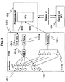
- Fig. 2 shows outline of signal flow in the instrument constitution shown in Fig. 1 .
- the probe unit 101 is provided with one or a plurality of the irradiation parts 1011 for irradiating light onto the living body, and one or a plurality of light detection parts 1012 for detecting irradiated light transmitting through or reflecting from the living body.
- the driving signal for the light source at the irradiation part 1011 is generated as the digital signal for amplitude modulation at a certain specific frequency or based on a certain kind of code at the modulator 1022 present inside the processing unit 102, and transmitted to the probe unit 101.
- the driving signal for light source is converted to the analog signal for amplitude modulation by the digital-to-analog converter 1013 in the probe unit 101, and transmitted to one driving device for light sources 1014.
- the analog signal for amplitude modulation is converted to the driving signal for the light source, and transmitted to one or each of a plurality of the irradiation parts 1011, by the multiplexer 1015, with a timing shifted as shown in Fig. 6 .
- intensity-modulated light is emitted, based on the driving signal for the light source, and sequentially irradiated onto the living body.
- the intensity-modulated light transmitting through or reflecting from the living body, is output as the analog signal for amplitude modulation.
- These analog signals for amplitude modulation are converted to the digital signals for amplitude modulation in the analog-to-digital converter 1016 corresponding to each of the light detection parts 1012.
- These digital signals for amplitude modulation are assembled to one signal by the parallel-serial converter 1017, and transmitted to the processing unit 102 as one digital signal.
- the optical measurement instrument for the living body According to the optical measurement instrument for the living body, light irradiation from all of the irradiation parts 1011 becomes possible by using the multiplexer 1015. Therefore, it is not necessary to prepare the driving devices for light sources corresponding to each of the irradiation parts 1011, and thus use of only one driving device for light source 1014 is sufficient: this instrument constitution is essential in compact sizing of the instrument.
- each of the irradiation parts 1011 is provided with the monitor photodiode 109 to always detect the irradiated light power, and assemble the detected signals to one through a buffer memory 1018, transmit to the analog-digital converter 1019, and transmit to the processing unit 102, as a series of digital signals.
- all of the above processing to the transmission to this processing unit 102 may be carried out by using the analog-to-digital converter and the parallel-serial converter corresponding to the light detection parts 1012, similarly as in the constitution shown in Fig. 2 .
- a light power to be irradiated originally is represented as Ps
- a practically irradiated light power at certain time t changes to k(t) times original level
- the practically irradiated light power at certain time t becomes Ps ⁇ k(t).
- the irradiated light power of Ps ⁇ k(t), monitored by the monitor photodiode 109, is transmitted to the processing unit 102, and k(t) can be calculated by known value Ps.
- Pd(t) the detected light power to be detected originally by the light detection part 1012
- Pd(t) contains time variation of living body information obtained by light, transmitting through or reflecting from the inside of the living body, as the subject.
- the detected light power becomes Pd(t) ⁇ k(t), and detected as containing both of the time variation of the living body information and the time variation of the irradiated light power.
- the time variation k(t) of the irradiated light power is acquired in advance by the monitor photodiode 109 and the processing unit 102, the original signal Pd(t) can be recovered by dividing the detected light power with k(t), in any of real time processing or post-processing, by which measurement data of the living body information can be recorded, not affected by the irradiated light power accompanied by various causes such as temperature change of surrounding area or the like.
- the driving signal for light source is represented as V(t)
- V(t) the driving signal for the light source
- the irradiated light power can also be adjusted. Namely, by using k(t-1) obtained just before, at certain time t, V(t) ⁇ k(t-1) may be transmitted as the driving signal for the light source. In this way, light intensity ⁇ emitted at the irradiation part can be maintained nearly constant.
- Fig. 4 shows one example, and shows the irradiation parts 1011 and the light detection parts 1012 arranged in the probe unit 101.
- each of the light detection parts 1012 detects light irradiated by a plurality of the irradiation parts 1011, and in this case, because the light irradiation by the irradiation parts 1011 is separated timewise, by the multiplexer 1015 in Fig. 2 , each of the signals from any of the irradiation parts 1011 can be separated, based on irradiation timing processed in the processing unit 102.
- each of the irradiation parts 1011 is provided with the light source 1011a of a wavelength of ⁇ 1 and the light source 1011b of a wavelength of ⁇ 2, different from ⁇ 1, and the monitor photodiode 109 for monitoring light intensity of these two light sources, and in the light detection part 1012, four lights arrive from at least two irradiation parts 1011.
- the four detected light powers of light arrived to the light detection parts 1012 are represented as P1, P2, P3 and P4 (level of the light power is in the order of P1 ⁇ P2 ⁇ P3 ⁇ P4). Because they are based on light irradiated separately timewise by the multiplexer 1015, the light power can be evaluated independently.
- the irradiated light power can be adjusted by matching with the detected light power levels by giving feedback so as to make each of the driving signals for the light sources (P4/P1) times, (P4/P2) times, and (P4/P3) times, in the processing unit 102.
- a safety standard level Pb has been set in advance to control, in the processing unit 102, so that the irradiated light power, detected at the monitor photodiode 109, does not to exceed Pb.
- the irradiated light powers of four light sources are represented by Ps1, Ps2, Ps3, and Ps4, and provided that Ps2 ⁇ Pb ⁇ Ps3, feedback is given to the driving signal for the light source in the processing unit 102, so as to make each of the irradiated light powers (Pb/Ps1) times, (Pb/Ps2) times, (Pb/Ps3) and (Pb/Ps4) times.
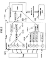
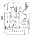
- the digital signal for amplitude modulation, based on the first modulation frequency or the first code, is emitted, which is transmitted to the first digital-analog converter 1013 via the cable 900; based on this, the first driving signal for the light source is emitted in the first driving device for the light source 1014, which is transmitted to the first multiplexer 1015; the first driving signal for the light source is distributed to the m1 irradiation parts 1011 by the first multiplexer 1015, to irradiate light on the subject, as well as, in the second modulator 2022 provided at the processing unit 102, the digital signal for amplitude modulation, based on the second modulation frequency without correlation to the first modulation frequency, or the second code without correlation to the first code, is emitted, which is transmitted to the second digital-analog converter 2013 via the cable 900; based on this, the second driving signal for the light source is emitted in the second driving device 2014 for
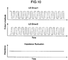
- the second driving device for the light source 2014 and the light detection part 1012 are supplied power from the same power source part 500, and in the case where the analog driving signal for the light source, which is output from the first driving device for the light source 1014 and the second driving device for the light source 2014, is subjected to amplitude modulation in a rectangular wave by a certain specific frequency, impedance fluctuation is generated with amplitude modulation viewed from the power source part 500. Therefore, it may be possible for the fluctuation with the modulation to enter the light detection part 1012 as noise.
- the living body information processed and acquired by the processing unit 102 is instantaneously transmitted to the processing part 300 by the cable 302 that connects the processing unit 102 and the probe unit 101, and then transmitted to each of the display parts 301 by the processing part 300.
- the display parts 301 may be visual display instrument such as LED, liquid crystal or the like; voice and sound providing instrument such as a speaker or the like; a vibration instrument such as a vibrator or the like; a temperature exhibiting instrument by using a thermistor or the like.
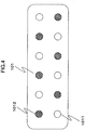
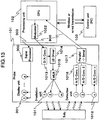
- FIG. 12 shows a surface mounting example, in the case where living body information to be displayed is two kinds, and the display part 301 is provided at the front surface of the probe unit 101, and the irradiation parts 1011 and the light detection parts 1012 at the rear surface thereof.
- the irradiation parts 1011 and the light detection parts 1012 shown by a broken line represent presence at the rear surface.
- Fig. 12 shows an example where living body information is acquired at nearly the mid-point of the irradiation parts 1011 and the light detection parts 1012, and the display parts 301 are arranged at a place where living body information is estimated to be acquired, however, the display parts 301 may be surface mounted at a suitable arrangement position, if necessary.
- the first display parts 3011 for displaying the first living body information, and the second display parts 3012 for displaying the second living body information are present.
- the first display parts 3011 and the second display parts 3012 are both LEDs and are display parts for showing concentrations of two kinds of specific substances in the living body, as the living body information, by increasing emission power with increase in the concentrations of the substances, or by decreasing emission power with decrease in the concentrations of the substances, concentration change of each substance, as living body information, can be instantaneously displayed.
- concentration change of each substance, as living body information can be instantaneously displayed.
- the display parts 301 can be controlled by the cable 303, which is provided inside the probe unit 101, as substitution for the cable 302, so as to transmit signals, acquired by the light detection part 1012, to the processing part 300 without passing through the processing unit 102, and subjecting to processing necessary to acquire living body information, at the processing part 300.
- the optical measurement instrument for the living body proposed and realized not only to remove an optical fiber, used in a conventional optical measurement instrument for the living body, but also to make compact sizing of a practical instrument, by instrument constitution characterized by being provided with the digital-to-analog converter, the driving device for the light source, the multiplexer, the analog-to-digital converter and the parallel-serial converter, inside the probe unit.
- instrument constitution characterized by being provided with the digital-to-analog converter, the driving device for the light source, the multiplexer, the analog-to-digital converter and the parallel-serial converter, inside the probe unit.
Landscapes
- Health & Medical Sciences (AREA)
- Life Sciences & Earth Sciences (AREA)
- Physics & Mathematics (AREA)
- General Health & Medical Sciences (AREA)
- Engineering & Computer Science (AREA)
- Pathology (AREA)
- Heart & Thoracic Surgery (AREA)
- Medical Informatics (AREA)
- Veterinary Medicine (AREA)
- Public Health (AREA)
- Animal Behavior & Ethology (AREA)
- Biophysics (AREA)
- Surgery (AREA)
- Biomedical Technology (AREA)
- Molecular Biology (AREA)
- Chemical & Material Sciences (AREA)
- Spectroscopy & Molecular Physics (AREA)
- Biochemistry (AREA)
- Analytical Chemistry (AREA)
- Immunology (AREA)
- General Physics & Mathematics (AREA)
- Artificial Intelligence (AREA)
- Computer Vision & Pattern Recognition (AREA)
- Physiology (AREA)
- Psychiatry (AREA)
- Signal Processing (AREA)
- Measurement Of The Respiration, Hearing Ability, Form, And Blood Characteristics Of Living Organisms (AREA)
- Investigating Or Analysing Materials By Optical Means (AREA)
Applications Claiming Priority (1)
| Application Number | Priority Date | Filing Date | Title |
|---|---|---|---|
| JP2007014436A JP5018105B2 (ja) | 2007-01-25 | 2007-01-25 | 生体光計測装置 |
Publications (2)
| Publication Number | Publication Date |
|---|---|
| EP1949848A1 EP1949848A1 (en) | 2008-07-30 |
| EP1949848B1 true EP1949848B1 (en) | 2018-05-23 |
Family
ID=39294047
Family Applications (1)
| Application Number | Title | Priority Date | Filing Date |
|---|---|---|---|
| EP07022042.1A Not-in-force EP1949848B1 (en) | 2007-01-25 | 2007-11-13 | Optical measurement instrument for living body |
Country Status (4)
| Country | Link |
|---|---|
| US (1) | US8244324B2 (enExample) |
| EP (1) | EP1949848B1 (enExample) |
| JP (1) | JP5018105B2 (enExample) |
| CN (1) | CN101229054B (enExample) |
Families Citing this family (14)
| Publication number | Priority date | Publication date | Assignee | Title |
|---|---|---|---|---|
| JP5192971B2 (ja) * | 2008-10-01 | 2013-05-08 | 浜松ホトニクス株式会社 | 光生体計測装置用のプローブおよび光生体計測装置 |
| JP5443075B2 (ja) * | 2009-06-30 | 2014-03-19 | 株式会社日立製作所 | ゲームシステム、生体光計測装置 |
| JP5573845B2 (ja) * | 2009-12-01 | 2014-08-20 | 株式会社島津製作所 | 光計測システム、それに用いられる携帯型光計測装置及びその使用方法 |
| US20140018686A1 (en) * | 2011-03-29 | 2014-01-16 | Pedro J. Medelius | Data collection unit power and noise management |
| WO2013150629A1 (ja) * | 2012-04-05 | 2013-10-10 | 株式会社島津製作所 | 光計測システム |
| KR101494535B1 (ko) | 2012-08-08 | 2015-02-24 | 한양대학교 산학협력단 | 근적외선 광원을 이용한 빔 조사 장치 |
| CN102920464B (zh) * | 2012-11-23 | 2014-12-24 | 扬州奥泰光电生物技术有限公司 | 血红蛋白浓度和血氧饱和度测定仪及测定方法 |
| JP5676688B2 (ja) * | 2013-06-11 | 2015-02-25 | Necソリューションイノベータ株式会社 | 光学ユニット及び光学分析装置 |
| JP6555503B2 (ja) * | 2015-01-13 | 2019-08-07 | 株式会社リコー | 光学センサ、光学検査装置、及び光学特性検出方法 |
| JP6592900B2 (ja) * | 2015-01-15 | 2019-10-23 | 株式会社リコー | 光学センサ、光学検査装置、被検体内部特性推定方法、及び被検体内部情報計測方法 |
| CN104688242A (zh) * | 2015-03-12 | 2015-06-10 | 深圳欧德蒙科技有限公司 | 生理参数检测装置和方法 |
| JP2017023455A (ja) * | 2015-07-23 | 2017-02-02 | 株式会社アドバンテスト | 近赤外光生体計測装置及びそのプローブ |
| JP6609738B2 (ja) | 2016-02-10 | 2019-11-27 | 株式会社NeU | 生体光計測装置及び生体光計測方法 |
| CN113951832A (zh) * | 2021-11-22 | 2022-01-21 | 武汉资联虹康科技股份有限公司 | 一种头戴式近红外脑功能成像系统及与其相适配的电极帽 |
Citations (5)
| Publication number | Priority date | Publication date | Assignee | Title |
|---|---|---|---|---|
| GB2311854A (en) * | 1995-11-17 | 1997-10-08 | Hitachi Ltd | Instrument for optical measurement of living body |
| WO1999040842A1 (en) * | 1998-02-13 | 1999-08-19 | Non-Invasive Technology, Inc. | Transabdominal examination, monitoring and imaging of tissue |
| US6240309B1 (en) * | 1995-10-06 | 2001-05-29 | Hitachi, Ltd. | Optical measurement instrument for living body |
| US20020068859A1 (en) * | 2000-12-01 | 2002-06-06 | Knopp Christina A. | Laser diode drive scheme for noise reduction in photoplethysmographic measurements |
| US20040030231A1 (en) * | 2002-08-08 | 2004-02-12 | Norris Mark A. | Oximeter with nulled op-amp current feedback |
Family Cites Families (25)
| Publication number | Priority date | Publication date | Assignee | Title |
|---|---|---|---|---|
| US3960140A (en) * | 1971-02-18 | 1976-06-01 | Buxton Richard L | Physiological monitoring system |
| JPS6446439A (en) * | 1987-08-17 | 1989-02-20 | Hamamatsu Photonics Kk | Diagnostic apparatus |
| US4819752A (en) * | 1987-10-02 | 1989-04-11 | Datascope Corp. | Blood constituent measuring device and method |
| JP2772040B2 (ja) * | 1989-06-23 | 1998-07-02 | コーリン電子株式会社 | 酸素飽和度測定装置 |
| US5299120A (en) * | 1989-09-15 | 1994-03-29 | Hewlett-Packard Company | Method for digitally processing signals containing information regarding arterial blood flow |
| JPH0593403A (ja) | 1991-04-30 | 1993-04-16 | Nippon Steel Corp | 防音鉄道軌道 |
| US5368026A (en) * | 1993-03-26 | 1994-11-29 | Nellcor Incorporated | Oximeter with motion detection for alarm modification |
| US5492118A (en) * | 1993-12-16 | 1996-02-20 | Board Of Trustees Of The University Of Illinois | Determining material concentrations in tissues |
| US5553615A (en) * | 1994-01-31 | 1996-09-10 | Minnesota Mining And Manufacturing Company | Method and apparatus for noninvasive prediction of hematocrit |
| JPH08117209A (ja) | 1994-10-20 | 1996-05-14 | Hitachi Ltd | 生体光計測プローブ |
| US6517283B2 (en) * | 2001-01-16 | 2003-02-11 | Donald Edward Coffey | Cascading chute drainage system |
| US5638816A (en) * | 1995-06-07 | 1997-06-17 | Masimo Corporation | Active pulse blood constituent monitoring |
| JPH0998972A (ja) | 1995-10-06 | 1997-04-15 | Hitachi Ltd | 生体光計測装置及び画像作成方法 |
| JP3682793B2 (ja) | 1995-11-30 | 2005-08-10 | 株式会社日立製作所 | 光による散乱体内部画像化装置 |
| JP3593764B2 (ja) | 1995-11-29 | 2004-11-24 | 株式会社日立製作所 | 生体光計測装置 |
| JP4055266B2 (ja) | 1998-10-13 | 2008-03-05 | 株式会社日立製作所 | 光計測装置 |
| JP3967062B2 (ja) | 2000-04-10 | 2007-08-29 | 株式会社日立メディコ | プローブ装置 |
| JP3842019B2 (ja) | 2000-06-29 | 2006-11-08 | 株式会社日立製作所 | 生体光計測装置及び生体光計測用固定具 |
| US6816241B2 (en) * | 2000-09-26 | 2004-11-09 | Sensys Medical, Inc. | LED light source-based instrument for non-invasive blood analyte determination |
| JP2002150123A (ja) | 2000-11-10 | 2002-05-24 | Sony Corp | 協賛依頼条件入力装置、協賛取引仲介サーバ及び協賛依頼受信装置 |
| JP4067762B2 (ja) | 2000-12-28 | 2008-03-26 | ヤマハ株式会社 | 歌唱合成装置 |
| JP2003322612A (ja) | 2002-04-30 | 2003-11-14 | Communication Research Laboratory | 脳活動計測装置、脳活動計測用頭部装着具 |
| JP2004121702A (ja) * | 2002-10-07 | 2004-04-22 | Hitachi Ltd | 生体光計測装置 |
| JP4489385B2 (ja) | 2002-12-12 | 2010-06-23 | 株式会社日立メディコ | 計測プローブ及び生体光計測装置 |
| JP2004248961A (ja) | 2003-02-21 | 2004-09-09 | Hitachi Medical Corp | 計測器具装着用ヘルメット |
-
2007
- 2007-01-25 JP JP2007014436A patent/JP5018105B2/ja not_active Expired - Fee Related
- 2007-11-13 EP EP07022042.1A patent/EP1949848B1/en not_active Not-in-force
- 2007-11-16 US US11/941,296 patent/US8244324B2/en not_active Expired - Fee Related
- 2007-12-04 CN CN2007101971084A patent/CN101229054B/zh not_active Expired - Fee Related
Patent Citations (5)
| Publication number | Priority date | Publication date | Assignee | Title |
|---|---|---|---|---|
| US6240309B1 (en) * | 1995-10-06 | 2001-05-29 | Hitachi, Ltd. | Optical measurement instrument for living body |
| GB2311854A (en) * | 1995-11-17 | 1997-10-08 | Hitachi Ltd | Instrument for optical measurement of living body |
| WO1999040842A1 (en) * | 1998-02-13 | 1999-08-19 | Non-Invasive Technology, Inc. | Transabdominal examination, monitoring and imaging of tissue |
| US20020068859A1 (en) * | 2000-12-01 | 2002-06-06 | Knopp Christina A. | Laser diode drive scheme for noise reduction in photoplethysmographic measurements |
| US20040030231A1 (en) * | 2002-08-08 | 2004-02-12 | Norris Mark A. | Oximeter with nulled op-amp current feedback |
Also Published As
| Publication number | Publication date |
|---|---|
| EP1949848A1 (en) | 2008-07-30 |
| CN101229054B (zh) | 2011-11-30 |
| US20080183056A1 (en) | 2008-07-31 |
| JP2008178563A (ja) | 2008-08-07 |
| JP5018105B2 (ja) | 2012-09-05 |
| CN101229054A (zh) | 2008-07-30 |
| US8244324B2 (en) | 2012-08-14 |
Similar Documents
| Publication | Publication Date | Title |
|---|---|---|
| EP1949848B1 (en) | Optical measurement instrument for living body | |
| US5349952A (en) | Photoplethysmographics using phase-division multiplexing | |
| US6505133B1 (en) | Simultaneous signal attenuation measurements utilizing code division multiplexing | |
| US20120310062A1 (en) | Photon density wave based determination of physiological blood parameters | |
| US9861305B1 (en) | Method and apparatus for calibration to reduce coupling between signals in a measurement system | |
| US7541602B2 (en) | System and method for noninvasively monitoring conditions of a subject | |
| US9084569B2 (en) | Method and apparatus for reducing coupling between signals in a measurement system | |
| EP1238627A2 (en) | Medical sensor and information system | |
| WO2007117839A3 (en) | Method and apparatus for using an optical hemodynamic sensor to identify an unstable arrhythmia | |
| WO1997049330A1 (en) | Motion artifact resistant oximeter using three wavelengths | |
| JPS63275325A (ja) | 診断装置 | |
| EP1568320A1 (en) | Simultaneous signal attenuation measurements utilizing frequency orthogonal random codes | |
| KR102500765B1 (ko) | 분광기, 분광기의 출력이득 조절 방법, 생체정보 측정 장치 및 방법 | |
| WO2011044079A1 (en) | Photoacoustic spectroscopy with focused light | |
| US20190257759A1 (en) | Signal processing device of analyzing bio-signal and bio-signal analyzing apparatus using the same | |
| JP2007532188A (ja) | 空間的に均等のマルチカラーソースを用いたフォトプレチスモグラフィ | |
| WO2014022925A1 (en) | Method and system for optically investigating a tissue of a subject | |
| JP4028249B2 (ja) | 目的物の成分濃度測定装置 | |
| EP1380253B1 (en) | Optical system for measuring metabolism in a body | |
| US20130317325A1 (en) | Apparatus and method for measurement of physiological parameters in tissue of a patient | |
| US8712492B2 (en) | Photon density wave based determination of physiological blood parameters | |
| JP4412667B2 (ja) | 成分濃度測定装置 | |
| JP2006326223A (ja) | 成分濃度測定装置 | |
| KR20180090107A (ko) | 분광기 및 그 분광기가 적용된 성분 측정 장치 | |
| JP2007111461A (ja) | 生体の光計測装置 |
Legal Events
| Date | Code | Title | Description |
|---|---|---|---|
| PUAI | Public reference made under article 153(3) epc to a published international application that has entered the european phase |
Free format text: ORIGINAL CODE: 0009012 |
|
| 17P | Request for examination filed |
Effective date: 20080331 |
|
| AK | Designated contracting states |
Kind code of ref document: A1 Designated state(s): AT BE BG CH CY CZ DE DK EE ES FI FR GB GR HU IE IS IT LI LT LU LV MC MT NL PL PT RO SE SI SK TR |
|
| AX | Request for extension of the european patent |
Extension state: AL BA HR MK RS |
|
| 17Q | First examination report despatched |
Effective date: 20081008 |
|
| AKX | Designation fees paid |
Designated state(s): DE NL |
|
| STAA | Information on the status of an ep patent application or granted ep patent |
Free format text: STATUS: EXAMINATION IS IN PROGRESS |
|
| RIC1 | Information provided on ipc code assigned before grant |
Ipc: A61B 5/00 20060101AFI20170928BHEP |
|
| GRAP | Despatch of communication of intention to grant a patent |
Free format text: ORIGINAL CODE: EPIDOSNIGR1 |
|
| STAA | Information on the status of an ep patent application or granted ep patent |
Free format text: STATUS: GRANT OF PATENT IS INTENDED |
|
| INTG | Intention to grant announced |
Effective date: 20171218 |
|
| RIN1 | Information on inventor provided before grant (corrected) |
Inventor name: HORITA, TADAHIRO Inventor name: ATSUMORI, HIROKAZU Inventor name: KIGUCHI, MASASHI |
|
| GRAS | Grant fee paid |
Free format text: ORIGINAL CODE: EPIDOSNIGR3 |
|
| GRAA | (expected) grant |
Free format text: ORIGINAL CODE: 0009210 |
|
| STAA | Information on the status of an ep patent application or granted ep patent |
Free format text: STATUS: THE PATENT HAS BEEN GRANTED |
|
| AK | Designated contracting states |
Kind code of ref document: B1 Designated state(s): DE NL |
|
| REG | Reference to a national code |
Ref country code: DE Ref legal event code: R096 Ref document number: 602007054903 Country of ref document: DE |
|
| REG | Reference to a national code |
Ref country code: NL Ref legal event code: MP Effective date: 20180523 |
|
| PG25 | Lapsed in a contracting state [announced via postgrant information from national office to epo] |
Ref country code: NL Free format text: LAPSE BECAUSE OF FAILURE TO SUBMIT A TRANSLATION OF THE DESCRIPTION OR TO PAY THE FEE WITHIN THE PRESCRIBED TIME-LIMIT Effective date: 20180523 |
|
| REG | Reference to a national code |
Ref country code: DE Ref legal event code: R097 Ref document number: 602007054903 Country of ref document: DE |
|
| PLBE | No opposition filed within time limit |
Free format text: ORIGINAL CODE: 0009261 |
|
| STAA | Information on the status of an ep patent application or granted ep patent |
Free format text: STATUS: NO OPPOSITION FILED WITHIN TIME LIMIT |
|
| 26N | No opposition filed |
Effective date: 20190226 |
|
| PGFP | Annual fee paid to national office [announced via postgrant information from national office to epo] |
Ref country code: DE Payment date: 20210929 Year of fee payment: 15 |
|
| REG | Reference to a national code |
Ref country code: DE Ref legal event code: R119 Ref document number: 602007054903 Country of ref document: DE |
|
| PG25 | Lapsed in a contracting state [announced via postgrant information from national office to epo] |
Ref country code: DE Free format text: LAPSE BECAUSE OF NON-PAYMENT OF DUE FEES Effective date: 20230601 |