EP1947434A2 - Magnetstriktiver Dehnungssensor - Google Patents
Magnetstriktiver Dehnungssensor Download PDFInfo
- Publication number
- EP1947434A2 EP1947434A2 EP07123909A EP07123909A EP1947434A2 EP 1947434 A2 EP1947434 A2 EP 1947434A2 EP 07123909 A EP07123909 A EP 07123909A EP 07123909 A EP07123909 A EP 07123909A EP 1947434 A2 EP1947434 A2 EP 1947434A2
- Authority
- EP
- European Patent Office
- Prior art keywords
- core
- coil
- strain sensor
- sensor according
- aperture
- Prior art date
- Legal status (The legal status is an assumption and is not a legal conclusion. Google has not performed a legal analysis and makes no representation as to the accuracy of the status listed.)
- Withdrawn
Links
- 239000000463 material Substances 0.000 claims abstract description 52
- 230000004907 flux Effects 0.000 claims abstract description 34
- 230000035699 permeability Effects 0.000 claims abstract description 27
- 238000000034 method Methods 0.000 claims abstract description 5
- 239000012530 fluid Substances 0.000 claims description 12
- 239000007787 solid Substances 0.000 claims description 5
- 238000002847 impedance measurement Methods 0.000 claims 1
- 238000005259 measurement Methods 0.000 claims 1
- 239000002283 diesel fuel Substances 0.000 abstract description 5
- 230000001133 acceleration Effects 0.000 abstract description 4
- 238000010276 construction Methods 0.000 abstract description 4
- 239000011162 core material Substances 0.000 description 71
- 230000008859 change Effects 0.000 description 18
- PXHVJJICTQNCMI-UHFFFAOYSA-N Nickel Chemical compound [Ni] PXHVJJICTQNCMI-UHFFFAOYSA-N 0.000 description 16
- 230000000694 effects Effects 0.000 description 11
- 229910052759 nickel Inorganic materials 0.000 description 8
- 229910000640 Fe alloy Inorganic materials 0.000 description 7
- 238000013461 design Methods 0.000 description 7
- UGKDIUIOSMUOAW-UHFFFAOYSA-N iron nickel Chemical compound [Fe].[Ni] UGKDIUIOSMUOAW-UHFFFAOYSA-N 0.000 description 7
- 230000008901 benefit Effects 0.000 description 5
- 230000006835 compression Effects 0.000 description 5
- 238000007906 compression Methods 0.000 description 5
- 229910000831 Steel Inorganic materials 0.000 description 4
- 239000003921 oil Substances 0.000 description 4
- 239000010959 steel Substances 0.000 description 4
- 229910001030 Iron–nickel alloy Inorganic materials 0.000 description 3
- 229910045601 alloy Inorganic materials 0.000 description 3
- 239000000956 alloy Substances 0.000 description 3
- 238000003466 welding Methods 0.000 description 3
- 229910000990 Ni alloy Inorganic materials 0.000 description 2
- 229910001329 Terfenol-D Inorganic materials 0.000 description 2
- 230000008030 elimination Effects 0.000 description 2
- 238000003379 elimination reaction Methods 0.000 description 2
- 230000010354 integration Effects 0.000 description 2
- 238000004519 manufacturing process Methods 0.000 description 2
- 239000010705 motor oil Substances 0.000 description 2
- 230000008569 process Effects 0.000 description 2
- 230000004044 response Effects 0.000 description 2
- 238000004804 winding Methods 0.000 description 2
- 229910001313 Cobalt-iron alloy Inorganic materials 0.000 description 1
- RYGMFSIKBFXOCR-UHFFFAOYSA-N Copper Chemical compound [Cu] RYGMFSIKBFXOCR-UHFFFAOYSA-N 0.000 description 1
- 229910001240 Maraging steel Inorganic materials 0.000 description 1
- 238000013459 approach Methods 0.000 description 1
- 238000002485 combustion reaction Methods 0.000 description 1
- 239000012141 concentrate Substances 0.000 description 1
- 239000004020 conductor Substances 0.000 description 1
- 230000007812 deficiency Effects 0.000 description 1
- 238000011161 development Methods 0.000 description 1
- 235000012489 doughnuts Nutrition 0.000 description 1
- 230000002500 effect on skin Effects 0.000 description 1
- 230000001747 exhibiting effect Effects 0.000 description 1
- 230000005307 ferromagnetism Effects 0.000 description 1
- 239000000446 fuel Substances 0.000 description 1
- JSUIEZRQVIVAMP-UHFFFAOYSA-N gallium iron Chemical compound [Fe].[Ga] JSUIEZRQVIVAMP-UHFFFAOYSA-N 0.000 description 1
- 238000003754 machining Methods 0.000 description 1
- 239000000696 magnetic material Substances 0.000 description 1
- 230000013011 mating Effects 0.000 description 1
- 238000012986 modification Methods 0.000 description 1
- 230000004048 modification Effects 0.000 description 1
- 230000000704 physical effect Effects 0.000 description 1
- 230000009467 reduction Effects 0.000 description 1
- 238000012546 transfer Methods 0.000 description 1
Images


Classifications
-
- G—PHYSICS
- G01—MEASURING; TESTING
- G01L—MEASURING FORCE, STRESS, TORQUE, WORK, MECHANICAL POWER, MECHANICAL EFFICIENCY, OR FLUID PRESSURE
- G01L9/00—Measuring steady of quasi-steady pressure of fluid or fluent solid material by electric or magnetic pressure-sensitive elements; Transmitting or indicating the displacement of mechanical pressure-sensitive elements, used to measure the steady or quasi-steady pressure of a fluid or fluent solid material, by electric or magnetic means
- G01L9/16—Measuring steady of quasi-steady pressure of fluid or fluent solid material by electric or magnetic pressure-sensitive elements; Transmitting or indicating the displacement of mechanical pressure-sensitive elements, used to measure the steady or quasi-steady pressure of a fluid or fluent solid material, by electric or magnetic means by making use of variations in the magnetic properties of material resulting from the application of stress
-
- G—PHYSICS
- G01—MEASURING; TESTING
- G01L—MEASURING FORCE, STRESS, TORQUE, WORK, MECHANICAL POWER, MECHANICAL EFFICIENCY, OR FLUID PRESSURE
- G01L1/00—Measuring force or stress, in general
- G01L1/12—Measuring force or stress, in general by measuring variations in the magnetic properties of materials resulting from the application of stress
- G01L1/125—Measuring force or stress, in general by measuring variations in the magnetic properties of materials resulting from the application of stress by using magnetostrictive means
-
- G—PHYSICS
- G01—MEASURING; TESTING
- G01L—MEASURING FORCE, STRESS, TORQUE, WORK, MECHANICAL POWER, MECHANICAL EFFICIENCY, OR FLUID PRESSURE
- G01L1/00—Measuring force or stress, in general
- G01L1/12—Measuring force or stress, in general by measuring variations in the magnetic properties of materials resulting from the application of stress
- G01L1/127—Measuring force or stress, in general by measuring variations in the magnetic properties of materials resulting from the application of stress by using inductive means
Definitions
- the present invention relates to a magnetostrictive strain sensor with an airgapless core.
- Magnetostrictive strain sensors are known and examples are disclosed and claimed in U.S. Patent Nos. 6,941,824, issued September 13, 2005 , and 6,993,983 issued February 7, 2006 , both assigned to the assignee of the subject invention.
- An inductance coil extends around an axis for establishing a loop of magnetic flux looping axially through the core and extending around the coil to define a donut shaped ring of magnetic flux surrounding the coil.
- a core made of a magnetostrictive material, such as a Nickel-Iron alloy provides a primary path for the magnetic flux in a first portion of the loop of magnetic flux.
- a magnetic carrier provides a return path for the magnetic flux in a second portion of the loop of magnetic flux as the magnetic flux circles the coil through the core and the carrier.
- the permeability of the magnetostrictive core thus the inductance of such a device, is a function of the strain applied to the core along the axis. The coil inductance therefore provides a useful signal.
- the coil can be excited with an AC voltage or AC current to induce an alternating magnetic field in the core. This field loops around the coil, and will possibly travel through other elements and materials, such as airgaps, and other matter.
- Magnetostrictive sensor concepts are described in Publication US 2006/0150743 A1, published July 13, 2006 , US Patent No. 7,104,137, issued September 12, 2006 , and Publication U.S. 2006/0086191, published April 27, 2006 .
- Magnetostrictive materials have a permeability that varies with stress (Villari effect).
- stress is sensed by measuring the inductance of a coil (usually of a copper wire) wound around a core made of a magnetostrictive material such as a nickel-iron alloy.
- These conventional sensors have at least 2 parts, a coil and a core.
- the core is made of at least two parts, so that the coil can be both wound around the inner part of the core, and surrounded by the outer part of the core.
- the inductance depends not only on the permeability of the core material(s), but also on any airgaps between the various parts of the core.
- This invention overcomes this problem by using a seamless, one-piece core.
- US Patent Nos. 4,541,288 and 4,561,314 show a coil wound around a toroidal core made of amorphous material, a type of material that exhibits magnetoelasticity.
- a superficial resemblance magneticelasticity, toroidal core
- These patents use a different aspect of the magnetoelastic effect, where the saturation flux density of a material is affected by stress (see Fig. 1a in US Patent No. 4,561,314 ).
- Applicants teach materials with a permeability that depends on stress.
- the inductance of the coil is measured, and, because inductance is affected by airgaps, airgap elimination is more than an advantage, it is a practical necessity.
- saturation flux density is used as a sensing principle
- electronic circuits such as the one described in U.S. Patent No. 4,541,288 are used. Airgaps or the absence thereof are not as critical.
- the amorphous material used in these patents cannot be manufactured in bulk, and is available only in ribbon form. Given the typical thinness of these ribbons, it would not be practical to use a single ribbon to form the core. Several ribbons must be stacked together to form the core. Therefore, the core is not a single-piece core.
- the toroidal shape of the design in these patents is a convenient way to accommodate a stack of ribbons. The reference is not motivated by a need to eliminate airgaps.
- the present invention overcomes deficiencies found in the prior art by measuring the inductance of a coil for a strain sensor comprising a monolithic magnetostrictive material core while essentially eliminating the effect of airgaps upon inductance.
- This invention relates to a strain sensor comprising a monolithic magnetostrictive material airgapless core, wherein permeability of the material depends on stress; the core having an aperture therein; and a coil, wound about the core and through the aperture; the core and the coil being configured such that when the coil is connected in circuit, it establishes a loop of magnetic flux that circulates through the core and about the coil, whereby impedance of the core is measured.
- the invention further relates to a strain sensor comprising a monolithic magnetostrictive material airgapless core, wherein permeability of the material depends on stress; the core having a groove therein; and a coil, wound about the core and through the groove; the core and the coil being configured such that when the coil is connected in circuit, it establishes a loop of magnetic flux that circulates through the core and about the coil, whereby impedance of the core is measured.
- the invention also relates to the above strain sensor integrated in a sensor plug useful for sensing the pressure of diesel fuel in common rail diesel engine systems, oil pressure in engine oil systems, oil pressure in hydraulic actuators for backhoes and other earth moving and construction vehicles.
- the invention further relates to a method for measuring stress utilizing the mentioned strain sensor in which impedance of the core is measured in the substantial absence of the effect of airgaps between coil and core upon impedance.
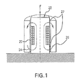
- Fig. 1 is a cross sectional view of a prior art magnetostrictive force sensor
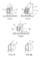
- Fig. 2 is a cross sectional view of a monolithic magnetic core according to the present invention.
- Fig. 3 is a rectangular monolithic core according to the present invention.
- Fig. 4 is a cross sectional view according to the present invention and Figures 4A and 4B are cross sectional views of Fig. 4 taken along line AA, Figure 4A shows a hollow cylinder, while Figure 4B is not hollow;
- Fig. 5 is a cylindrical horizontal monolithic core according to the subject invention.
- Fig. 6 is a toroidal monolithic core and Figure 6A is a cross sectional view taken along line AA;
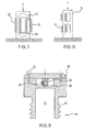
- Fig. 7 shows multiple coils on a monolithic core according to the subject invention
- Fig. 8 shows multiple coils each wound around multiple apertures in a monolithic core according to the present invention
- Fig. 9 is a schematic representation of a pressure sensor plug utilizing a strain sensor according to the present invention.
- Figs. 10A and 10B show a front view and a side view, respectively, of a strain sensor according to the present invention integrated into a system being measured;
- Fig. 11 shows a cross sectional view of a strain sensor according to the present invention integrated into a conduit of magnetostrictive material.
- Magnetostriction denotes the following physical effect: The change in the dimension of a body when it is magnetized. More specifically, Joule magnetostriction is the change in the length of a body when it is magnetized. Joule magnetostriction can be positive (the change in length with field is positive), or negative (the change in length with field is negative), depending on the material.
- the inverse effect is the change in permeability of a magnetic material with an applied stress.
- magnetostrictive materials Materials which exhibit a magnetostrictive effect, especially those exhibiting a large magnetostrictive effect, are called magnetostrictive materials.
- a magnetostrictive stress sensor (such as the one described in our invention) therefore uses the Villari effect on magnetostriction, and Villari effect are often overlooked and all are denoted " magnetostrictive devices.”
- FIG. 1 A typical strain sensor is shown in Fig. 1 .
- the source of stress is a force applied vertically on a core 22 made of a magnetostrictive material.
- Other typical sources of stress are pressure, torque, and acceleration.
- the coil is wound around the core.
- An outside member serves as a carrier 24 for the flux return, and is placed around the coil to close the magnetic flux path 26.
- the core and carrier are distinct so that the coil 20 can be easily wound. In this construction, there are necessarily interfaces between the core and carrier, which will constitute airgaps 27.
- the type of magnetostrictive material used in the present sensors has a permeability that depends on stress.
- examples of such materials are nickel-iron alloys (both maraging steels, with lower nickel content, around 18%, and regular nickel-iron alloys, with nickel content between 20% and 100%), galfenol, terfenol, etc. So the changing permeability can be sensed by measuring the inductance of the coil for instance by exciting the coil with a small, constant amplitude current and reading the voltage across the coil.
- useful magnetostrictive materials are: Nickel-iron alloys (alloys with more than 20% nickel content), maraging steels (nickel alloys with less than 20% nickel), cobalt-iron alloys, Terfenol, or galliumiron alloys (known as Galfenol), especially for sensors used in compression mode; pure nickel alloy with a large percentage of nickel, especially for sensors used in tension mode.
- the most useful materials are nickel-iron alloys in general, and maraging steels for those instances where the stress level is particularly high.
- Galfenol is a new and promising material. Steels in general exhibit some magnetostriction but much smaller.
- the present invention overcomes this difficulty using a single-piece core 22, and winding a coil 20 through an aperture 28, as shown in Fig. 2 .
- Monolithic means made of a single, solid piece can be machined down from a larger piece, or molded into shape, from a single mold. Includes no airgap, separating film, or mating surface within, in any plane, whether in the direction parallel to the magnetic flux, normal to the magnetic flux, etc.
- Some processes such as welding two separate parts together will yield a piece which has the appearance of being monolithic.
- the welding process cannot be guaranteed to leave no separating airgap, or separating film of welding material within, therefore it cannot product a monolithic piece.
- the monolithic core can be implemented in various geometries. Various examples are shown in the drawings, all in the context of force sensing.
- Fig. 3 shows a rectangular or parallel-piped core 22.
- Other core configurations are shown in Fig. 4 (cylindrical), Fig. 5 (cylindrical in a horizontal plane), and Fig. 6 (toroidal).
- the configuration in Fig. 5 is a cylinder that may include a flat area 28 at the bottom, which is illustrated, and/or one flat area on top, which is not shown, for stability of the core.
- part of the magnetic flux path is in line with the stress in the material (here generally in the direction of the force), while other parts are normal to the stress.
- Those skilled in the art know how to align flux and stress lines to produce a change in permeability in a magnetostrictive material.
- a design can take advantage of the type of magnetostriction of the material used in the fabrication of the sensor. This is because the magnetostrictive effect is strong when the magnetic flux lines are aligned with, or normal with, the stress, depending on whether it is a compressive or a tensile stress, and depending on the material.
- two designs are possible: with some materials (with a negative magnetostriction coefficient), the conductor width should be larger than its height; and, the opposite for other materials (with a positive magnetostriction coefficient).
- magnetostriction has either a positive or negative coefficient.
- Table I Conditions for materials with a negative magnetostriction coefficient Materials with a negative magnetostriction coefficient Stress in line with flux Stress normal to flux Tensile stress Very small change in permeability Large change in permeability Compression stress Large change in permeability Very small change in permeability Table II: Conditions for materials with a positive magnetostriction coefficient Materials with a positive magnetostriction coefficient Stress in line with flux Stress normal to flux Tensile stress Large change in permeability Very small change in permeability Compression stress Very small change in permeability Large change in permeability
- a desirable type of material is a nickel-iron alloy, because it exhibits a large coefficient ⁇ , and is relatively strong and inexpensive.
- Nickel-iron alloys can exhibit either a positive or negative coefficient of magnetostriction, depending on the nickel content of the alloy. R. J. Bozorth, p. 616.
- the magnetic flux lines must be in line with the stress lines.
- the flux lines must be normal to the stress.
- the coil 20 For the toroidal shape, the coil 20 must be recessed, as shown on Fig. 6 , or the force applied only to part of the toroidal, so that the force does not bear on the coil.
- the sensing unit may include more than one coil. Having several coils 30, 32 can be useful for redundancy, to cancel EMI noise, or for cancellation of disturbances such as temperature. Another coil may be wound on the same core 22, see Fig. 7 . If several coils are used, they may be wound through different holes, see Fig. 8 ; importantly, however, each coil is wound around a single-piece core 22.
- FIG. 9 An example of a pressure sensor application is shown in Fig. 9 .
- a fluid 42 under pressure circulates in a pipe or hydraulic circuit (now shown).
- the sensor 36 according to the invention is placed within an assembly, generally looking in the case of Fig. 9 like a plug 44, which can be threaded into the pipe or hydraulic circuit.
- the plug has a cavity for the fluid at one end (the threaded end) 40 and a blind hole 38 for the sensing unit 36 at the other end.
- the blind hole 38 is separated from the fluid cavity by a wall 39 having sufficient thickness to be sturdy, but sufficiently thin to transfer stress to the sensor unit. 1 or 2 mm is considered appropriate.
- Wall 39 is different from the diaphragms used in other pressure sensors such as strain gauge sensors.
- Strain gauge pressure sensors are known and commercially available, see for instance US Patent 7,131,334 .
- a diaphragm is used, like wall 39, to isolate the pressurized fluid from the attached strain gauge, which serves as the sensing element.
- a diaphragm must be sufficiently flexible and deformable to apply stress to the strain gauge.
- Wall 39 does not deform. The force exerted on wall 39 by the pressure is directly transmitted to the sensor core 22.
- the sensing unit consists of a single-piece core 22 with a hole through which the coil(s) is wound.
- Fig. 9 shows an example of a rectangular (like Fig. 3 ) or cylindrical (like Fig. 4 ) core.
- the blind hole is closed with a cover 46 that ensures a tight fit for the sensing unit within.
- This example is useful for sensing the pressure of diesel fuel in common rail diesel engine systems, oil pressure in engine oil systems, oil pressure in hydraulic actuators for back hoes and other earth moving and construction vehicles, etc.
- the single-piece core system presented here offers a unique opportunity to integrate the sensor 36 physically with the system where it is used.
- the pressure sensor 36 shown in Fig. 9 consists of 3 parts: the plug 44 with a cavity and a blind hole 38, the sensor unit (core 22 and coil 20) and the cover 46.
- the sensor could be made in one piece as shown in Fig. 10 .
- the wall separating the fluid from the sensing coil constitutes a portion of the core.
- the present concept can be implemented by a single step of making one through hole 48 close to the area the pressure of which is monitored, and winding a coil 20 through that hole 48.
- An example is shown in Fig. 11 .
- the wall separating the fluid from the sensing coil is both a part of the pipe, and at the same time constitutes a portion of the core.
- This invention concerns development of a pressure sensor for withstanding higher pressures. Examples are common rail diesel fuel sensors, and combustion chamber pressure sensors (gasoline or diesel).
- a distinctive feature is the blind hole 38 in which the sensor 36 is fitted (see Fig. 9 ), or the single piece integration of the core 22 with the overall mechanical part itself ( Fig. 10 ).
- the configuration of Fig. 10 is simpler to manufacture and is a practical design.
- the cylindrical configuration of Fig. 4 (hollow, alternative 4A) is desirable because it is axisymmetric (except for the hole for the coil), axisymmetric like the fuel cavity underneath, and therefore, like the stress pattern. Being hollow the cylinder further concentrates stress in a thin portion of the core where the flux is also flowing. So the walls of the cylinder will see uniform, relatively high levels of stress.
- the outside diameter of the cylinder of Fig. 4 will be selected by considering the following strategy.
- About the wall thickness because of skin effects, the magnetic flux is limited to a depth of only a portion of a millimeter, so a thinner wall is desirable. A thicker wall would see proportionally less stress.
- About diameter a large diameter encompasses more stress ( ⁇ x wall thickness x diameter); however, the stress level is maximum in the center of the device, therefore, a large diameter sees a lower level of stress. A trade-off is therefore necessary.
- a wall thickness of 0.5 mm, and an outside diameter of 4.8 mm can be used. The hole is approximately square, 2mm x 2 mm.
- maraging steel is used as a material combining both strength and magnetostriction.
- frequencies as low as 100 Hz are sufficient. Desirable values of frequencies can be either in the ranges 1 to 15 kHz or 15 to 50 kHz. Both of these ranges would provide adequate sensor dynamic response, and allow the force sensor to follow fast motion. For example, the force pattern experienced during the motion of a vehicle brake system, if the sensor is part of such a system.
- the lower range (1 to 15 kHz) has the advantage of avoiding the range of frequencies usually selected for motor control, thus minimizing interference if the sensor is close to a motor.
- the higher range (15 to 50 kHz) has the advantage of being inaudible for humans. It would also allow for yet higher dynamic response.
- a sensor assembly for measuring force along an axis in accordance with the subject invention is shown in various embodiments in figures wherein like parts or portions are indicated with like numerals.
- At least one inductance coil having multiple turns or coils, or multiple coils each having one or more turns or coils, extends around the force axis for establishing a loop of magnetic flux (shown by the arrows) looping axially through the coil and extending around the axis to define a ring of magnetic flux surrounding the coil.
- a loop of magnetic flux shown by the arrows
- the self-inductance of the coil is calculated and measured.
- Alternative embodiments may include several coils, either connected in series or separately, and "inductance" should be understood as, more generally, self-inductance or mutual inductance.
- the force axis happens to coincide with a geometrical axis of symmetry.
- the word "force axis" should be understood broadly as the direction of the force, or the direction of the force path, through the core.
- the force axis or force path may, or may not be an axis of symmetry; it may, or may not be, a line, and one could envision situations where this path or axis is not straight but curved. It could also be a surface rather than a line.
Landscapes
- Physics & Mathematics (AREA)
- General Physics & Mathematics (AREA)
- Measuring Fluid Pressure (AREA)
Applications Claiming Priority (1)
| Application Number | Priority Date | Filing Date | Title |
|---|---|---|---|
| US11/653,682 US20080168844A1 (en) | 2007-01-16 | 2007-01-16 | Magnetostrictive strain sensor (airgap control) |
Publications (2)
| Publication Number | Publication Date |
|---|---|
| EP1947434A2 true EP1947434A2 (de) | 2008-07-23 |
| EP1947434A3 EP1947434A3 (de) | 2010-07-07 |
Family
ID=39276350
Family Applications (1)
| Application Number | Title | Priority Date | Filing Date |
|---|---|---|---|
| EP07123909A Withdrawn EP1947434A3 (de) | 2007-01-16 | 2007-12-21 | Magnetstriktiver Dehnungssensor |
Country Status (2)
| Country | Link |
|---|---|
| US (1) | US20080168844A1 (de) |
| EP (1) | EP1947434A3 (de) |
Families Citing this family (13)
| Publication number | Priority date | Publication date | Assignee | Title |
|---|---|---|---|---|
| CA2685250A1 (en) * | 2007-05-16 | 2008-11-27 | Thomson Licensing | Apparatus and method for encoding and decoding signals |
| US20090107248A1 (en) * | 2007-10-24 | 2009-04-30 | Thaddeus Schroeder | Magnetostrictive sensor with uniform stress |
| US7816797B2 (en) * | 2009-01-07 | 2010-10-19 | Oscilla Power Inc. | Method and device for harvesting energy from ocean waves |
| US8820180B2 (en) * | 2009-11-30 | 2014-09-02 | Goodrich Corporation | Monolithic magneto-strictive load transducer |
| US8378512B2 (en) * | 2010-02-01 | 2013-02-19 | Oscilla Power Inc. | Wave energy harvester with improved performance |
| US20120086205A1 (en) * | 2010-10-08 | 2012-04-12 | Balakrishnan Nair | Method and device for harvesting energy from ocean waves |
| CN102175359B (zh) * | 2011-02-11 | 2012-08-01 | 重庆大学 | 钢索/杆构件应力的无源式磁性监测方法及装置 |
| US20130291657A1 (en) * | 2012-04-02 | 2013-11-07 | Ashish S. Purekar | Apparatus and method for non contact sensing of forces and motion on rotating shaft |
| US9212958B2 (en) | 2012-12-28 | 2015-12-15 | General Electric Company | Non-contact magnetostrictive sensing systems and methods |
| JP5914827B2 (ja) * | 2013-11-27 | 2016-05-11 | パナソニックIpマネジメント株式会社 | 力センサ及びそれを用いた力検知装置、並びに力検知方法 |
| US9784627B2 (en) | 2013-11-27 | 2017-10-10 | Panasonic Intellectual Property Management Co., Ltd. | Load sensor, load detector including load sensor, and method for detecting load |
| DE102017104329A1 (de) * | 2017-03-02 | 2018-09-06 | Wobben Properties Gmbh | Generator, Messeinrichtung, Verwendung einer Messeinrichtung, Verfahren zum Betreiben eines Generators, Windenergieanlage und Verfahren zum Betreiben einer Windenergieanlage |
| US11428589B2 (en) | 2017-10-16 | 2022-08-30 | Saf-Holland, Inc. | Displacement sensor utilizing ronchi grating interference |
Citations (8)
| Publication number | Priority date | Publication date | Assignee | Title |
|---|---|---|---|---|
| US4541288A (en) | 1983-10-27 | 1985-09-17 | General Electric Company | Operating circuit for magnetoelastic force/pressure sensors |
| US4561314A (en) | 1983-10-27 | 1985-12-31 | General Electric Company | Magnetoelastic force/pressure sensor |
| US6941824B2 (en) | 2003-04-25 | 2005-09-13 | Delphi Technologies, Inc. | Magnetic force sensor and control circuit for same |
| US6993983B2 (en) | 2002-12-06 | 2006-02-07 | Delphi Technologies, Inc. | Universal magnetostrictive force sensor |
| US20060086191A1 (en) | 2004-10-25 | 2006-04-27 | Morelli Donald T | Magnetostrictive strain sensor and method |
| US20060150743A1 (en) | 2005-01-11 | 2006-07-13 | Lequesne Bruno P B | Magnetostrictive strain sensor (airgap control) |
| US7104137B2 (en) | 2004-04-20 | 2006-09-12 | Delphi Technologies, Inc. | Magnetostrictive fluid-pressure sensor |
| US7131334B2 (en) | 2004-04-19 | 2006-11-07 | Celerity, Inc. | Pressure sensor device and method |
Family Cites Families (22)
| Publication number | Priority date | Publication date | Assignee | Title |
|---|---|---|---|---|
| US2053560A (en) * | 1932-06-27 | 1936-09-08 | Siemens Ag | Device for measuring mechanical forces and momenta |
| US2370845A (en) * | 1942-02-18 | 1945-03-06 | Davis Hunt | Measurement of stress |
| US2749746A (en) * | 1953-07-14 | 1956-06-12 | Gen Electric | Magnetostriction strain gauge |
| US3168830A (en) * | 1963-03-25 | 1965-02-09 | Int Resistance Co | Pressure transducer |
| US3681982A (en) * | 1968-09-08 | 1972-08-08 | Yaskawa Denki Seisakusho Kk | Transducer system for detecting and measuring mechanical loads or stresses |
| US3717039A (en) * | 1969-08-04 | 1973-02-20 | Int Technical Ind | Method and means for amplifying the stress and strain in a stress-sensitive component |
| DE2215232A1 (de) * | 1971-03-30 | 1972-10-05 | Yaskawa Denki Seisakusho Kk | Vorrichtung zur Messung von mechanischen Kräften |
| FR2206847A5 (de) * | 1972-11-15 | 1974-06-07 | Aquitaine Petrole | |
| US4138783A (en) * | 1973-10-09 | 1979-02-13 | Soletanche | Method for measuring stresses or forces |
| US3940992A (en) * | 1973-12-26 | 1976-03-02 | Texas Instruments Incorporated | Transducer |
| JPS6022287B2 (ja) * | 1980-07-17 | 1985-06-01 | 松下電器産業株式会社 | 圧力センサ |
| JPS5737233A (en) * | 1980-08-18 | 1982-03-01 | Matsushita Electric Ind Co Ltd | Tension sensor |
| SE455886B (sv) * | 1986-12-15 | 1988-08-15 | Asea Ab | Magnetoelastisk kraftgivare |
| SE457116B (sv) * | 1987-04-30 | 1988-11-28 | Asea Ab | Magnetoelastisk kraftgivare |
| US5437197A (en) * | 1993-08-20 | 1995-08-01 | The Board Of Governors Of Wayne State University | Magnetostrictive sensor structures |
| US5747696A (en) * | 1996-10-28 | 1998-05-05 | Temic Bayern-Chemie Airbag Gmbh | Method of non-invasively monitoring pressure of a compressed gas in a closed container |
| US6622577B1 (en) * | 1997-10-07 | 2003-09-23 | Mehmet H. Uras | Single coil magnetostrictive sensors |
| DE19924002A1 (de) * | 1999-05-26 | 2000-11-30 | Wittenstein Gmbh & Co Kg | Sensor, insbesondere magnetiostriktiver oder magnetoelastischer Sensor |
| DE10111541A1 (de) * | 2001-03-10 | 2002-09-19 | Bosch Gmbh Robert | Magnetoelastischer Kraftmessring nach dem Kreuz-Ringduktorprinzip |
| US20040093951A1 (en) * | 2002-11-20 | 2004-05-20 | Viola Jeffrey L. | Magnetoelastic pressure sensor |
| US6972560B2 (en) * | 2003-04-22 | 2005-12-06 | Delphi Technologies, Inc. | Method for detecting a change in permeability of a magnetostrictive object |
| US20060016277A1 (en) * | 2004-07-23 | 2006-01-26 | Nehl Thomas W | Non-invasive magnetostrictive sensor |
-
2007
- 2007-01-16 US US11/653,682 patent/US20080168844A1/en not_active Abandoned
- 2007-12-21 EP EP07123909A patent/EP1947434A3/de not_active Withdrawn
Patent Citations (8)
| Publication number | Priority date | Publication date | Assignee | Title |
|---|---|---|---|---|
| US4541288A (en) | 1983-10-27 | 1985-09-17 | General Electric Company | Operating circuit for magnetoelastic force/pressure sensors |
| US4561314A (en) | 1983-10-27 | 1985-12-31 | General Electric Company | Magnetoelastic force/pressure sensor |
| US6993983B2 (en) | 2002-12-06 | 2006-02-07 | Delphi Technologies, Inc. | Universal magnetostrictive force sensor |
| US6941824B2 (en) | 2003-04-25 | 2005-09-13 | Delphi Technologies, Inc. | Magnetic force sensor and control circuit for same |
| US7131334B2 (en) | 2004-04-19 | 2006-11-07 | Celerity, Inc. | Pressure sensor device and method |
| US7104137B2 (en) | 2004-04-20 | 2006-09-12 | Delphi Technologies, Inc. | Magnetostrictive fluid-pressure sensor |
| US20060086191A1 (en) | 2004-10-25 | 2006-04-27 | Morelli Donald T | Magnetostrictive strain sensor and method |
| US20060150743A1 (en) | 2005-01-11 | 2006-07-13 | Lequesne Bruno P B | Magnetostrictive strain sensor (airgap control) |
Non-Patent Citations (2)
| Title |
|---|
| BOZORTH, R. M.: "magnetostrictive devices", 1993, WILEY-INTERSCIENCE, IEEE PRESS |
| R. M. BOZORTH: "Ferromagnetism", 2003, IEEE PRESS, WILEY-INTERSCIENCE, JOHN WILEY & SONS, INC. |
Also Published As
| Publication number | Publication date |
|---|---|
| US20080168844A1 (en) | 2008-07-17 |
| EP1947434A3 (de) | 2010-07-07 |
Similar Documents
| Publication | Publication Date | Title |
|---|---|---|
| EP1947434A2 (de) | Magnetstriktiver Dehnungssensor | |
| EP0675342B1 (de) | Magnetostriktiver Wandler | |
| US10962433B2 (en) | Pressure sensor and pressure measuring method | |
| US6622577B1 (en) | Single coil magnetostrictive sensors | |
| CN115183798B (zh) | 用于线性可变差动变压器(lvdt)探针的c形圆柱形芯 | |
| US5789918A (en) | Temperature compensated differential transformer and a measuring device using the same | |
| US4780671A (en) | Magnetically operated non-contact magnetic torque sensor for shafts | |
| US20200284672A1 (en) | Magnetostriction type torque detection sensor | |
| JPH0643927B2 (ja) | 磁気弾性式力測定装置 | |
| JP7416724B2 (ja) | 応力検出装置 | |
| JPS628031A (ja) | 油圧センサ | |
| JP2003194639A (ja) | 力センサ | |
| WO1999045601A3 (en) | Magnetostrictive stress sensor | |
| US7234361B2 (en) | Magnetostrictive strain sensor (airgap control) | |
| EP1619486A2 (de) | Nichtinvasiver magnetostriktiver Sensor | |
| CN219038226U (zh) | 一种振弦式传感器及压力计 | |
| US8707793B2 (en) | Sensor system having a magnetoelastic deformation element | |
| EP2053374A2 (de) | Magnetostriktiver Sensor mit gleichmässiger Belastung | |
| CA1180744A (en) | Magnetoelastic transducer | |
| JP5187099B2 (ja) | 磁歪式応力センサ | |
| JP2005180950A (ja) | 荷重センサ及びその製造方法 | |
| JP2005009911A (ja) | 荷重センサ | |
| JPS6231864Y2 (de) | ||
| JPH0862063A (ja) | 磁歪式歪センサ | |
| JPH04259838A (ja) | 圧力センサ |
Legal Events
| Date | Code | Title | Description |
|---|---|---|---|
| PUAI | Public reference made under article 153(3) epc to a published international application that has entered the european phase |
Free format text: ORIGINAL CODE: 0009012 |
|
| AK | Designated contracting states |
Kind code of ref document: A2 Designated state(s): AT BE BG CH CY CZ DE DK EE ES FI FR GB GR HU IE IS IT LI LT LU LV MC MT NL PL PT RO SE SI SK TR |
|
| AX | Request for extension of the european patent |
Extension state: AL BA HR MK RS |
|
| PUAL | Search report despatched |
Free format text: ORIGINAL CODE: 0009013 |
|
| AK | Designated contracting states |
Kind code of ref document: A3 Designated state(s): AT BE BG CH CY CZ DE DK EE ES FI FR GB GR HU IE IS IT LI LT LU LV MC MT NL PL PT RO SE SI SK TR |
|
| AX | Request for extension of the european patent |
Extension state: AL BA HR MK RS |
|
| STAA | Information on the status of an ep patent application or granted ep patent |
Free format text: STATUS: THE APPLICATION IS DEEMED TO BE WITHDRAWN |
|
| 18D | Application deemed to be withdrawn |
Effective date: 20100701 |