EP2053374A2 - Magnetostriktiver Sensor mit gleichmässiger Belastung - Google Patents
Magnetostriktiver Sensor mit gleichmässiger Belastung Download PDFInfo
- Publication number
- EP2053374A2 EP2053374A2 EP08166353A EP08166353A EP2053374A2 EP 2053374 A2 EP2053374 A2 EP 2053374A2 EP 08166353 A EP08166353 A EP 08166353A EP 08166353 A EP08166353 A EP 08166353A EP 2053374 A2 EP2053374 A2 EP 2053374A2
- Authority
- EP
- European Patent Office
- Prior art keywords
- core
- stress
- central longitudinal
- longitudinal axis
- fluid
- Prior art date
- Legal status (The legal status is an assumption and is not a legal conclusion. Google has not performed a legal analysis and makes no representation as to the accuracy of the status listed.)
- Withdrawn
Links
Images

Classifications
-
- G—PHYSICS
- G01—MEASURING; TESTING
- G01L—MEASURING FORCE, STRESS, TORQUE, WORK, MECHANICAL POWER, MECHANICAL EFFICIENCY, OR FLUID PRESSURE
- G01L9/00—Measuring steady of quasi-steady pressure of fluid or fluent solid material by electric or magnetic pressure-sensitive elements; Transmitting or indicating the displacement of mechanical pressure-sensitive elements, used to measure the steady or quasi-steady pressure of a fluid or fluent solid material, by electric or magnetic means
- G01L9/16—Measuring steady of quasi-steady pressure of fluid or fluent solid material by electric or magnetic pressure-sensitive elements; Transmitting or indicating the displacement of mechanical pressure-sensitive elements, used to measure the steady or quasi-steady pressure of a fluid or fluent solid material, by electric or magnetic means by making use of variations in the magnetic properties of material resulting from the application of stress
Definitions
- the present invention relates generally to magnetostrictive (MS) stress sensors.
- Magnetostrictive stress sensors can be used to measure stress such as might be generated within the sensor by fluid pressure.
- a MS stress sensor includes a magnetostrictive (MS) core made of a material, such as a nickel iron alloy, and a coil that surrounds the core for establishing magnetic flux within the core. The flux loop continues through the medium on the exterior of the coil. The core provides a primary path for the magnetic flux in a first portion of the of magnetic flux loop.
- a ferromagnetic carrier either MS or non-MS, can be used to provide an improved return path for the magnetic flux in a second portion of the magnetic flux loop, as the magnetic flux circles the coil through the core and the carrier.
- the permeability ofthe MS core, and thus the inductance of the coil, is a function of the stress applied to the core along the axis.
- the value of the coil inductance therefore represents the magnitude of the stress applied to the core and, hence, the magnitude of the physical phenomenon causing the stress, such as fluid pressure on the core.
- the stress within the MS core optimally should be uniform in the area of the core where stress is to be measured in order to optimize its measurement.
- a sensor assembly includes a sensor housing forming a fluid chamber that in turn defines a surface, with an axis normal to the surface.
- a magnetostrictive core is provided that defines a central longitudinal axis. The core is subjected to stress induced by pressurized fluid in the chamber.
- An excitation coil surrounds the core to induce a magnetic flux therein.
- the central longitudinal axis of the core is coaxial with the axis normal to the fluid chamber surface.
- the MS core may include a designated portion around which the coil is wound.
- This coil portion of the core defines the central longitudinal axis and can have a circular cross-section or a rectangular cross-section.
- the core can be "H"-shaped and the central longitudinal axis extends through the centers of the cross-members connecting the two core leg members rendering them equidistant from the central longitudinal axis.
- the coil portion of the core undergoes only compressive stress during operation.
- a sensor assembly in another aspect, includes a sensor housing forming a fluid chamber and a magnetostrictive core portion subjected to one and only one type of stress due to a force generated by pressurized fluid in the chamber.
- An excitation coil wound only around the coil portion of the core induces a magnetic flux therein.
- a sensor for outputting a signal representative of stress caused by a source of stress.
- the sensor includes magnetostrictive (MS) means defining a central longitudinal axis and juxtaposable with the source of stress such that the source of stress causes one and only one type of stress along the central longitudinal axis of the MS means.
- the sensor further includes signal means configured for carrying a signal representative of the one and only one type of stress along the central longitudinal axis of the MS means.
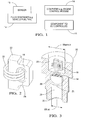
- Figure 1 shows a system in accordance with one non-limiting embodiment of the present invention
- Figure 2 is a perspective view of a first embodiment of a MS core
- Figure 3 is a cut-away perspective view of the core shown in Figure 2 in a sensor housing, with the coil and housing cover removed for clarity;
- Figure 4 is a partial cross-sectional view of an alternate sensor core in a sensor housing
- Figure 5 is a side view of the core and housing shown in Figure 4 .
- an MS stress sensor 10 can be coupled to a source of pressure, such as to a fluid container 12, with the MS stress sensor 10 having the ability to sense fluid pressure in the fluid container 12 in accordance with principles below.
- a source of pressure such as to a fluid container 12
- the fluid contain 12 may be, e.g., a vehicle fuel rail, an engine combustion chamber, etc., although present principles are not limited to any particular fluid application.
- the MS stress sensor 10 is also electronically connected to a computer 14 which may be, without limitation, an engine control module.
- the computer 14 receives the signal that is output by the sensor 10 for processing the signal to, e.g., correlate the stress as indicated by the signal to a fluid pressure.
- the computer 14 may be electronically connected to a component or components 16 such as a fluid pump, injectors, etc., that may be controlled by the computer 14 based on data received from the MS stress sensor 10.
- FIG. 2 A first embodiment of the MS stress sensor 10 is shown in Figures 2 and 3 . Beginning with Figure 2 , an MS core 18 is shown.
- the body 20 of the core 18 is parallelepiped in shape, but may also be cylindrical in shape to retain a greater degree of symmetry and so that high-stress areas do not occur near the corners of a parallelepiped-shaped core.
- an excitation coil 22 is coupled to the core 18. More specifically, the coil 22 is of a non-magnetic wire, such as e.g. copper, that is wound around core 18.
- the coil 22 is energized to induce a magnetic flux 24 in the MS core 18, and also serves as a transducer providing a signal representing the resulting magnetic flux, which in turn represents the stress of the MS core 18 and, hence, the pressure in the fluid.
- the magnetic flux 24 loops around the MS core 18.
- the coil can be wound anywhere around the core; it is shown by way of example in Fig. 2 wound around the body region 20 of the core 18. Also, a single coil 22 is shown in Fig. 2 , although several coils can be contemplated for redundancy, temperature compensation, etc.
- Figure 3 provides another view of the first embodiment of the MS stress sensor 10, this time representing a cross-section of the MS core 18 shown disposed within a sensor housing 26.
- the sensor housing comprises two cavities or chambers, a chamber 28 designed to receive the fluid under pressure, and a chamber 29 designed to receive the sensor unit (core 18 and coil 22).
- chambers 28 and 29 have a width Wfluid and Wsensor, respectively, in the plane of the figure (width, or diameter, or length, depending on respective chamber shapes).
- Wfluid and Wsensor There is no restrictions on the size of Wfluid and Wsensor.
- One or both could be large;, alternatively, one or both could be very small, for instance if the fluid chamber 28 is a narrow conduit designed to be connected to a relatively distant pressure chamber (such a design may be necessary for instance to isolate the sensing element from extreme temperatures).
- This part 25 of the sensor housing 26 is where the two chamber areas (widths Wfluid and Wsensor in the plane of the figure) overlap.
- This part 25 of the sensor housing 26 is also where the housing 26 is at its thinnest, so that the transmitted stress is maximized.
- the minimum thickness is limited by material strength and the maximum anticipated stress or burst pressure, which could be much larger than the maximum for normal operation. Thicknesses on the order of a fraction of a millimeter to a couple of millimeters are the most common.
- a point of maximum stress 34 is shown. This point of maximum stress 34 is typically located approximately in the geometric center of area 25.
- the area 25 of the sensor housing 26 includes a surface 21 on which the fluid under pressure applies stress.
- the surface 21 defines a direction normal to itself, and more specifically an axis 30 normal to surface 21 and located at the approximate geometric center of area 25, i.e. at or close to point 34 where the stress is maximum.
- the MS core 18 defines a central longitudinal axis 32 that is coaxial with the axis 30 normal to surface 21. The stress caused by the fluid pressure travels through the point of maximum stress 34, along the axis 32, and transfers to the body 20 of the core 18. In the presence of stress, the magnetic permeability of the body 20 of the core 18 changes affecting the inductance of the coil.
- stress may be applied to the body 20 of the core 18, but the rest of the core 18 is essentially not stressed.
- the rest of the core 18 is not stressed because the axis 32 extending through the body 20, i.e. the axis 32 ofthe core 18 region around which the coil 22 is wound, is collinear with the axis 30 normal to the surface 21 of the fluid chamber 28, causing stress to be transferred substantially only along the axes.
- FIG. 4 A second embodiment ofthe MS stress sensor 10 is shown in Figures 4 and 5 .
- a sensor housing 36 is shown, which is substantially similar to the sensor housing 26 from the first embodiment above, with the following exceptions.
- a MS core 38 upon which the coil 40 is wound is "H"-shaped in the second embodiment. That is, the MS core 38 includes two leg members 50 connected by cross-members 48. The cross-members 48 are located at some distance from the top and bottom of the leg members 50.
- the MS core 38 defines a central longitudinal axis 44.
- the sensor housing 36 defines a fluid chamber 42, a sensor chamber 49, and includes an area 45 where these two chambers 42 and 49 overlap. Further, the area 45 has a surface 41 separating area 45 and fluid chamber 42. In turn, this surface 41 defines an axis 46 normal to surface 41 and located approximately where the stress within area 45 is maximum. This axis 46 is coaxial with the central longitudinal axis 44 of the MS core 38. Specifically, as can be appreciated in cross-reference to Figures 4 and 5 , the axis 46 normal to the surface 41 of the fluid chamber 42 extends through the center of upper and lower cross-members 48 each of which connects the two leg members 50 of the MS core 38.
- the leg members 50 are equidistant from the central longitudinal axis 44 and are perpendicular to the cross-members 48.
- the coil 40 is shown wound around one of the leg members 50 between the cross-members 48, although coil 40 could also be wound around one of the two cross-members 48 between the leg members 50.
- FIG. 5 shows a pressure action arrow 52, representing fluid pressure from the fluid chamber 42.
- the pressure action arrow 52 indicates the direction of the force caused by the fluid pressure, the fluid pressure being caused by fluid in the fluid chamber 42.
- magnetic flux predominantly remains in the inner area of the core 38 as indicated by the vertical hatched areas 54 and horizontal hatched areas 56.
- the area hatched areas may be referred to as a skin effect area.
- cross-members 48 are located at some distance from the top and bottom of the leg members 50, they can be designed to experience essentially no stress. It can therefore be appreciated that stress affecting the core 38 is then confined substantially only to the vertical areas 54, which are under a single, compressive stress. The magnetic flux traverses these areas of uniform stress 54 as well as areas 56 under essentially no stress, resulting in a uniform stress-dependent signal.
- the materials used for the MS core may include but are not limited to nickel/iron alloys, pure nickel, terfenol, galfenol.
- Preferred non-limiting materials include maraging steel (steel with about 18% nickel content) and nickel-iron alloys with 30%-70% nickel content.
Landscapes
- Physics & Mathematics (AREA)
- General Physics & Mathematics (AREA)
- Measuring Fluid Pressure (AREA)
Applications Claiming Priority (1)
| Application Number | Priority Date | Filing Date | Title |
|---|---|---|---|
| US11/977,306 US20090107248A1 (en) | 2007-10-24 | 2007-10-24 | Magnetostrictive sensor with uniform stress |
Publications (2)
| Publication Number | Publication Date |
|---|---|
| EP2053374A2 true EP2053374A2 (de) | 2009-04-29 |
| EP2053374A3 EP2053374A3 (de) | 2010-07-07 |
Family
ID=40263565
Family Applications (1)
| Application Number | Title | Priority Date | Filing Date |
|---|---|---|---|
| EP08166353A Withdrawn EP2053374A3 (de) | 2007-10-24 | 2008-10-10 | Magnetostriktiver Sensor mit gleichmässiger Belastung |
Country Status (2)
| Country | Link |
|---|---|
| US (1) | US20090107248A1 (de) |
| EP (1) | EP2053374A3 (de) |
Families Citing this family (2)
| Publication number | Priority date | Publication date | Assignee | Title |
|---|---|---|---|---|
| US7816797B2 (en) * | 2009-01-07 | 2010-10-19 | Oscilla Power Inc. | Method and device for harvesting energy from ocean waves |
| US20120086205A1 (en) * | 2010-10-08 | 2012-04-12 | Balakrishnan Nair | Method and device for harvesting energy from ocean waves |
Family Cites Families (12)
| Publication number | Priority date | Publication date | Assignee | Title |
|---|---|---|---|---|
| GB410629A (en) * | 1932-06-27 | 1934-05-24 | Siemens Ag | Method of and apparatus for measuring mechanical forces, particularly for testing purposes |
| GB442441A (en) * | 1934-08-03 | 1936-02-03 | Frederick Daniel Smith | Magnetic pressure, tension, torsion and like stress measuring devices |
| US3681982A (en) * | 1968-09-08 | 1972-08-08 | Yaskawa Denki Seisakusho Kk | Transducer system for detecting and measuring mechanical loads or stresses |
| JPS4851658A (de) * | 1971-10-29 | 1973-07-20 | ||
| US4053137A (en) * | 1976-01-16 | 1977-10-11 | De Laval Turbine Inc. | Electromechanically operated valve |
| JP3311427B2 (ja) * | 1993-06-18 | 2002-08-05 | 株式会社デンソー | 複合磁性部材およびその製法およびこの複合磁性部材を用いた電磁弁 |
| GB0016852D0 (en) * | 2000-07-11 | 2000-08-30 | Newlands Technology Limited | Pressure sensor |
| US6539806B2 (en) * | 2001-03-07 | 2003-04-01 | Starr-Johnson | Fluid-load measurement by magnetic excitation and vibration sensing of a fluid-load-sensitive diaphragm |
| DE10127932A1 (de) * | 2001-06-08 | 2002-12-19 | Bosch Gmbh Robert | Ventil zum Steuern von Fluiden sowie Verfahren zur Bestimmung von Drücken |
| KR100848447B1 (ko) * | 2003-03-31 | 2008-07-28 | 티디케이가부시기가이샤 | 압력 센서 |
| US7104137B2 (en) * | 2004-04-20 | 2006-09-12 | Delphi Technologies, Inc. | Magnetostrictive fluid-pressure sensor |
| US20080168844A1 (en) * | 2007-01-16 | 2008-07-17 | Bruno Lequesne | Magnetostrictive strain sensor (airgap control) |
-
2007
- 2007-10-24 US US11/977,306 patent/US20090107248A1/en not_active Abandoned
-
2008
- 2008-10-10 EP EP08166353A patent/EP2053374A3/de not_active Withdrawn
Also Published As
| Publication number | Publication date |
|---|---|
| US20090107248A1 (en) | 2009-04-30 |
| EP2053374A3 (de) | 2010-07-07 |
Similar Documents
| Publication | Publication Date | Title |
|---|---|---|
| EP1947434A2 (de) | Magnetstriktiver Dehnungssensor | |
| CN102798333B (zh) | 传感器及传感器的制造方法 | |
| US7735373B2 (en) | Apparatus for measuring pressure in a vessel using magnetostrictive acoustic transducer | |
| CN103765237B (zh) | 用于磁致弹性的传感器的测量头 | |
| KR102370003B1 (ko) | 쇽 업소버를 위한 유도성 센서 | |
| US11927568B2 (en) | Double inductance coils for powering wireless ultrasound transducers | |
| EP2128581A1 (de) | Magnetostriktivanspannungssensor | |
| CN110389308A (zh) | 磁致伸缩/压电复合灵敏度倍增的磁力梯度探头 | |
| US6622577B1 (en) | Single coil magnetostrictive sensors | |
| EP2053374A2 (de) | Magnetostriktiver Sensor mit gleichmässiger Belastung | |
| US9995715B2 (en) | Electromagnetic transducer for exciting and sensing vibrations of resonant structures | |
| US20040093951A1 (en) | Magnetoelastic pressure sensor | |
| US20090107247A1 (en) | Magnetostrictive pressure sensor with an integrated sensing and sealing part | |
| CN113176016A (zh) | 钢绞线应力的检测方法、检测装置及其使用方法 | |
| JP2003194639A (ja) | 力センサ | |
| US7235970B2 (en) | Antenna core material for use in MWD resistivity measurements and NMR measurements | |
| US4030346A (en) | Magnetoelastic transducer arrangement | |
| EP1514128B1 (de) | Antennenkern-material zur verwendung bei mwd-widerstandsmessungen und bei nmr-messungen | |
| US10352681B2 (en) | Displacement detection device | |
| US7234361B2 (en) | Magnetostrictive strain sensor (airgap control) | |
| CN101750182B (zh) | 具有磁弹性变形元件的传感器装置 | |
| US5275049A (en) | Multicomponent acceleration sensor | |
| CN113176017B (zh) | 钢绞线体内预应力分布监测方法、监测系统及其使用方法 | |
| JP5187099B2 (ja) | 磁歪式応力センサ | |
| JP4164373B2 (ja) | 磁歪式荷重センサおよび荷重検出装置 |
Legal Events
| Date | Code | Title | Description |
|---|---|---|---|
| PUAI | Public reference made under article 153(3) epc to a published international application that has entered the european phase |
Free format text: ORIGINAL CODE: 0009012 |
|
| AK | Designated contracting states |
Kind code of ref document: A2 Designated state(s): AT BE BG CH CY CZ DE DK EE ES FI FR GB GR HR HU IE IS IT LI LT LU LV MC MT NL NO PL PT RO SE SI SK TR |
|
| AX | Request for extension of the european patent |
Extension state: AL BA MK RS |
|
| PUAL | Search report despatched |
Free format text: ORIGINAL CODE: 0009013 |
|
| AK | Designated contracting states |
Kind code of ref document: A3 Designated state(s): AT BE BG CH CY CZ DE DK EE ES FI FR GB GR HR HU IE IS IT LI LT LU LV MC MT NL NO PL PT RO SE SI SK TR |
|
| AX | Request for extension of the european patent |
Extension state: AL BA MK RS |
|
| AKY | No designation fees paid | ||
| REG | Reference to a national code |
Ref country code: DE Ref legal event code: R108 Effective date: 20110215 Ref country code: DE Ref legal event code: 8566 |
|
| STAA | Information on the status of an ep patent application or granted ep patent |
Free format text: STATUS: THE APPLICATION IS DEEMED TO BE WITHDRAWN |
|
| 18D | Application deemed to be withdrawn |
Effective date: 20110108 |