EP1946910A2 - Bildanordnung und Verfahren für die feste Bildgebung - Google Patents
Bildanordnung und Verfahren für die feste Bildgebung Download PDFInfo
- Publication number
- EP1946910A2 EP1946910A2 EP08000401A EP08000401A EP1946910A2 EP 1946910 A2 EP1946910 A2 EP 1946910A2 EP 08000401 A EP08000401 A EP 08000401A EP 08000401 A EP08000401 A EP 08000401A EP 1946910 A2 EP1946910 A2 EP 1946910A2
- Authority
- EP
- European Patent Office
- Prior art keywords
- build
- imager
- build material
- exposure
- imagers
- Prior art date
- Legal status (The legal status is an assumption and is not a legal conclusion. Google has not performed a legal analysis and makes no representation as to the accuracy of the status listed.)
- Granted
Links
- 238000003384 imaging method Methods 0.000 title claims abstract description 132
- 239000007787 solid Substances 0.000 title claims abstract description 107
- 238000000034 method Methods 0.000 title claims description 69
- 239000000463 material Substances 0.000 claims abstract description 290
- 230000005855 radiation Effects 0.000 claims abstract description 68
- 238000007711 solidification Methods 0.000 claims abstract description 10
- 230000008023 solidification Effects 0.000 claims abstract description 10
- 238000005286 illumination Methods 0.000 claims description 15
- 238000009826 distribution Methods 0.000 claims description 12
- 239000004973 liquid crystal related substance Substances 0.000 claims description 8
- 238000012545 processing Methods 0.000 claims description 8
- 230000004044 response Effects 0.000 claims description 8
- 238000002156 mixing Methods 0.000 claims description 7
- XUIMIQQOPSSXEZ-UHFFFAOYSA-N Silicon Chemical compound [Si] XUIMIQQOPSSXEZ-UHFFFAOYSA-N 0.000 claims description 4
- 229910052710 silicon Inorganic materials 0.000 claims description 4
- 239000010703 silicon Substances 0.000 claims description 4
- 230000032258 transport Effects 0.000 description 101
- 239000011248 coating agent Substances 0.000 description 88
- 238000000576 coating method Methods 0.000 description 88
- 239000010410 layer Substances 0.000 description 88
- 230000033001 locomotion Effects 0.000 description 19
- 238000001723 curing Methods 0.000 description 12
- 238000004519 manufacturing process Methods 0.000 description 11
- 230000008569 process Effects 0.000 description 9
- 238000012546 transfer Methods 0.000 description 9
- 230000006870 function Effects 0.000 description 8
- 238000006116 polymerization reaction Methods 0.000 description 8
- 238000004140 cleaning Methods 0.000 description 7
- 238000010586 diagram Methods 0.000 description 7
- 238000006073 displacement reaction Methods 0.000 description 6
- 238000010438 heat treatment Methods 0.000 description 5
- 239000007788 liquid Substances 0.000 description 5
- 230000007246 mechanism Effects 0.000 description 5
- 239000000203 mixture Substances 0.000 description 5
- 239000011347 resin Substances 0.000 description 5
- 229920005989 resin Polymers 0.000 description 5
- 238000009987 spinning Methods 0.000 description 5
- 238000012360 testing method Methods 0.000 description 5
- 230000008901 benefit Effects 0.000 description 4
- 238000012512 characterization method Methods 0.000 description 4
- 150000001875 compounds Chemical class 0.000 description 4
- 239000011159 matrix material Substances 0.000 description 4
- 230000003287 optical effect Effects 0.000 description 4
- 229920000193 polymethacrylate Polymers 0.000 description 4
- 206010073306 Exposure to radiation Diseases 0.000 description 3
- 230000002745 absorbent Effects 0.000 description 3
- 239000002250 absorbent Substances 0.000 description 3
- 238000013459 approach Methods 0.000 description 3
- 230000000712 assembly Effects 0.000 description 3
- 238000000429 assembly Methods 0.000 description 3
- 230000005540 biological transmission Effects 0.000 description 3
- 230000007423 decrease Effects 0.000 description 3
- 238000011143 downstream manufacturing Methods 0.000 description 3
- 230000001678 irradiating effect Effects 0.000 description 3
- 238000012986 modification Methods 0.000 description 3
- 230000004048 modification Effects 0.000 description 3
- 230000035515 penetration Effects 0.000 description 3
- 238000005070 sampling Methods 0.000 description 3
- 229920000742 Cotton Polymers 0.000 description 2
- 238000003491 array Methods 0.000 description 2
- 238000004364 calculation method Methods 0.000 description 2
- 239000002131 composite material Substances 0.000 description 2
- 238000010924 continuous production Methods 0.000 description 2
- 238000000151 deposition Methods 0.000 description 2
- 239000003085 diluting agent Substances 0.000 description 2
- 239000000835 fiber Substances 0.000 description 2
- 230000009969 flowable effect Effects 0.000 description 2
- 239000012530 fluid Substances 0.000 description 2
- 238000009472 formulation Methods 0.000 description 2
- 230000003116 impacting effect Effects 0.000 description 2
- 239000004417 polycarbonate Substances 0.000 description 2
- 239000000843 powder Substances 0.000 description 2
- 239000000523 sample Substances 0.000 description 2
- 230000003595 spectral effect Effects 0.000 description 2
- 229920001169 thermoplastic Polymers 0.000 description 2
- 230000009466 transformation Effects 0.000 description 2
- 241001270131 Agaricus moelleri Species 0.000 description 1
- 241000226585 Antennaria plantaginifolia Species 0.000 description 1
- 229920002799 BoPET Polymers 0.000 description 1
- JOYRKODLDBILNP-UHFFFAOYSA-N Ethyl urethane Chemical compound CCOC(N)=O JOYRKODLDBILNP-UHFFFAOYSA-N 0.000 description 1
- 239000004812 Fluorinated ethylene propylene Substances 0.000 description 1
- 239000005041 Mylar™ Substances 0.000 description 1
- 239000004677 Nylon Substances 0.000 description 1
- 239000004743 Polypropylene Substances 0.000 description 1
- 239000004809 Teflon Substances 0.000 description 1
- 229920006362 Teflon® Polymers 0.000 description 1
- 238000003848 UV Light-Curing Methods 0.000 description 1
- 238000010521 absorption reaction Methods 0.000 description 1
- 239000000853 adhesive Substances 0.000 description 1
- 230000001070 adhesive effect Effects 0.000 description 1
- 230000003679 aging effect Effects 0.000 description 1
- 230000004075 alteration Effects 0.000 description 1
- 238000000149 argon plasma sintering Methods 0.000 description 1
- 230000009286 beneficial effect Effects 0.000 description 1
- 230000000903 blocking effect Effects 0.000 description 1
- 230000008859 change Effects 0.000 description 1
- 239000011247 coating layer Substances 0.000 description 1
- 238000004891 communication Methods 0.000 description 1
- 229920001577 copolymer Polymers 0.000 description 1
- 238000012937 correction Methods 0.000 description 1
- 230000001186 cumulative effect Effects 0.000 description 1
- 230000008021 deposition Effects 0.000 description 1
- 238000011161 development Methods 0.000 description 1
- 230000018109 developmental process Effects 0.000 description 1
- 230000000694 effects Effects 0.000 description 1
- HQQADJVZYDDRJT-UHFFFAOYSA-N ethene;prop-1-ene Chemical group C=C.CC=C HQQADJVZYDDRJT-UHFFFAOYSA-N 0.000 description 1
- 239000011521 glass Substances 0.000 description 1
- 230000005484 gravity Effects 0.000 description 1
- 239000003999 initiator Substances 0.000 description 1
- 238000007641 inkjet printing Methods 0.000 description 1
- 238000007689 inspection Methods 0.000 description 1
- 230000010354 integration Effects 0.000 description 1
- 210000000050 mohair Anatomy 0.000 description 1
- 238000000465 moulding Methods 0.000 description 1
- 229920001778 nylon Polymers 0.000 description 1
- 239000003973 paint Substances 0.000 description 1
- 229920009441 perflouroethylene propylene Polymers 0.000 description 1
- 239000004033 plastic Substances 0.000 description 1
- 229920003023 plastic Polymers 0.000 description 1
- 229920000515 polycarbonate Polymers 0.000 description 1
- 229920000728 polyester Polymers 0.000 description 1
- 229920000642 polymer Polymers 0.000 description 1
- 239000003505 polymerization initiator Substances 0.000 description 1
- -1 polypropylene Polymers 0.000 description 1
- 229920001155 polypropylene Polymers 0.000 description 1
- 229920001296 polysiloxane Polymers 0.000 description 1
- 229920001343 polytetrafluoroethylene Polymers 0.000 description 1
- 239000004810 polytetrafluoroethylene Substances 0.000 description 1
- 230000001681 protective effect Effects 0.000 description 1
- 238000011084 recovery Methods 0.000 description 1
- 238000004064 recycling Methods 0.000 description 1
- 230000000717 retained effect Effects 0.000 description 1
- 238000005096 rolling process Methods 0.000 description 1
- 238000013341 scale-up Methods 0.000 description 1
- 239000007858 starting material Substances 0.000 description 1
- 239000000126 substance Substances 0.000 description 1
- 239000000758 substrate Substances 0.000 description 1
- 230000009897 systematic effect Effects 0.000 description 1
- 230000001131 transforming effect Effects 0.000 description 1
- 238000011282 treatment Methods 0.000 description 1
- 230000000007 visual effect Effects 0.000 description 1
Images


Classifications
-
- B—PERFORMING OPERATIONS; TRANSPORTING
- B33—ADDITIVE MANUFACTURING TECHNOLOGY
- B33Y—ADDITIVE MANUFACTURING, i.e. MANUFACTURING OF THREE-DIMENSIONAL [3-D] OBJECTS BY ADDITIVE DEPOSITION, ADDITIVE AGGLOMERATION OR ADDITIVE LAYERING, e.g. BY 3-D PRINTING, STEREOLITHOGRAPHY OR SELECTIVE LASER SINTERING
- B33Y30/00—Apparatus for additive manufacturing; Details thereof or accessories therefor
-
- B—PERFORMING OPERATIONS; TRANSPORTING
- B29—WORKING OF PLASTICS; WORKING OF SUBSTANCES IN A PLASTIC STATE IN GENERAL
- B29C—SHAPING OR JOINING OF PLASTICS; SHAPING OF MATERIAL IN A PLASTIC STATE, NOT OTHERWISE PROVIDED FOR; AFTER-TREATMENT OF THE SHAPED PRODUCTS, e.g. REPAIRING
- B29C64/00—Additive manufacturing, i.e. manufacturing of three-dimensional [3D] objects by additive deposition, additive agglomeration or additive layering, e.g. by 3D printing, stereolithography or selective laser sintering
- B29C64/20—Apparatus for additive manufacturing; Details thereof or accessories therefor
- B29C64/205—Means for applying layers
- B29C64/223—Foils or films, e.g. for transferring layers of building material from one working station to another
-
- B—PERFORMING OPERATIONS; TRANSPORTING
- B29—WORKING OF PLASTICS; WORKING OF SUBSTANCES IN A PLASTIC STATE IN GENERAL
- B29C—SHAPING OR JOINING OF PLASTICS; SHAPING OF MATERIAL IN A PLASTIC STATE, NOT OTHERWISE PROVIDED FOR; AFTER-TREATMENT OF THE SHAPED PRODUCTS, e.g. REPAIRING
- B29C64/00—Additive manufacturing, i.e. manufacturing of three-dimensional [3D] objects by additive deposition, additive agglomeration or additive layering, e.g. by 3D printing, stereolithography or selective laser sintering
- B29C64/20—Apparatus for additive manufacturing; Details thereof or accessories therefor
- B29C64/264—Arrangements for irradiation
-
- B—PERFORMING OPERATIONS; TRANSPORTING
- B33—ADDITIVE MANUFACTURING TECHNOLOGY
- B33Y—ADDITIVE MANUFACTURING, i.e. MANUFACTURING OF THREE-DIMENSIONAL [3-D] OBJECTS BY ADDITIVE DEPOSITION, ADDITIVE AGGLOMERATION OR ADDITIVE LAYERING, e.g. BY 3-D PRINTING, STEREOLITHOGRAPHY OR SELECTIVE LASER SINTERING
- B33Y50/00—Data acquisition or data processing for additive manufacturing
- B33Y50/02—Data acquisition or data processing for additive manufacturing for controlling or regulating additive manufacturing processes
-
- B—PERFORMING OPERATIONS; TRANSPORTING
- B29—WORKING OF PLASTICS; WORKING OF SUBSTANCES IN A PLASTIC STATE IN GENERAL
- B29C—SHAPING OR JOINING OF PLASTICS; SHAPING OF MATERIAL IN A PLASTIC STATE, NOT OTHERWISE PROVIDED FOR; AFTER-TREATMENT OF THE SHAPED PRODUCTS, e.g. REPAIRING
- B29C2791/00—Shaping characteristics in general
- B29C2791/001—Shaping in several steps
Definitions
- the invention relates generally to the field of solid imaging and to apparatus and methods for creating three-dimensional solid objects through the layer-by-layer build-up of radiation-solidifiable photopolymer build materials.
- Solid imaging devices fabricate three-dimensional objects from fusible powders or photocurable liquids, typically by exposure to radiation. Powders and liquids for solid imaging sometimes are referred to as “build materials” and the three-dimensional objects produced by solid imaging devices sometimes are called “builds,” “parts,” and “solid imaging products,” which can include a wide variety of shapes.
- Solid imaging includes many devices and methods to create three-dimensional objects, including by stereolithography, laser sintering, ink jet printing, and similar methods, which typically employ a layer-by-layer fabrication method. A laser or other source of radiation sequentially irradiates individual thin layers of the build material in response to which the material transforms to a solid, layer-upon-layer, to create a solid imaging product. More recent developments include flexible transport solid imaging devices and methods that are capable of using visible and ultraviolet light sources to irradiate build materials responsive to these wavelengths.
- Solid imaging devices produce products in batches rather than continuously or semi-continuously.
- Solid imaging devices produce "green" three-dimensional products, in which uncured build material wets the surface and causes the product to be tacky and to require cleaning prior to fully curing the product throughout the build.
- Another drawback of many solid imaging devices is the limitation on the size of the objects that can be built.
- the time required to build the object is directly related to the object's size because of limitations on the speed with which a laser can scan the surface of the cross-section.
- Laser scanners can be provided with higher resolution capabilities and with a large size laser spot for scanning larger areas at once, completing borders and fine details with a smaller spot, but the scanning speed remains significantly slower than that which can be achieved with a digital light processing (“DLP”) imager.
- DLP digital light processing
- DLP imagers employ mirror arrays in which selective control of each individual mirror between “on” and “off” positions produces the desired image in a fresh layer of photocurable build material.
- Each individual mirror correlates to a pixel, which is the smallest element of an image that can be individually processed in a display system for a two-dimensional image.
- DLP's and high resolution laser scanners have comparable minimum feature sizes. Imaging speed increases with a DLP as compared to a laser scanner because the individual mirrors in the DLP array can be controlled simultaneously to image an area of the build at one time, including an entire layer of a build, rather than by using a scanner to trace the image with a laser spot.
- DLP imager spreads the available radiation energy over a larger area, increasing the exposure time and reducing the resolution of the image.
- Commonly available imagers having a mirror array of 1024 x 768 pixels can expose a 9 x 6.75 inch area (22.9 x 17.14 cm area) in about 5 seconds and produce fine detail similar to that of a laser scanner.
- Increasing the image area to 18 x 13.5 inches (45.7 x 34.3 cm) increases exposure time to about 20 seconds and reduces fine detail twofold.
- Image dimensions can be increased by 37% with the same minimum feature size by replacing a DLP having a 1024 x 768 pixel array with a higher resolution DLP having a 1400 x 1024 pixel array. That is to say, the same object could be produced with the same detail in a 12.2 x 9 inch format (31.0 x 22.9 cm format) with the larger array compared to the 9 x 6.75 inch format (22.9 x 17.14 cm format) of the smaller array. Nevertheless, higher resolution DLP imagers do not resolve the problems of increased exposure time and reduced detail for larger objects.
- the larger array reduces image intensity by 45% and increases exposure time from 5 to 9.1 seconds, which is significant over the course of a build.
- the invention relates to solid imaging apparatus and methods for providing three-dimensional objects with greater efficiency.
- the invention provides builds that require less processing after the build is completed, either in its green state or fully cured.
- the invention includes in selected embodiments, if desired, one or more of the added capabilities of producing builds in either batch or semi-continuous mode in a tack free or nearly tack free condition, fully curing the builds, and producing builds with equivalent or better feature detail and in larger sizes than presently available.
- the apparatus and method of the invention can be incorporated into downstream manufacturing processes.
- the apparatus of the invention provides a source of radiation for solid imaging, one or more sources of solid imaging build material remote from a defined image plane, and at least one reciprocating transport surface that conveys build material layer-by-layer to the image plane from the one or more sources of build material.
- the build material typically will be a flowable material that easily can be transferred to the transport surface.
- the source of radiation hardens the layer of build material in the image plane.
- the radiation source emits light over a range of wave lengths to which the build material is responsive, typically visible and ultra-violet light.
- the image plane defines a surface in space for transforming the build material layer-by-layer to form the solid imaging product.
- a surface for retaining the solid imaging product cooperates with a source of radiation and at least one transport surface to create the image plane.
- the radiation source transforms the build material layer-by-layer into a solid built on the retaining surface.
- the source of build material applies a layer of the build material to the reciprocating transport surface in the image of the build layer and prior to transformation of the image into a cured layer on a build surface.
- substantially no uncured build material remains on the build surface or on the transport surface after irradiation of the image. Since the source of build material, typically an ink jet print head, produces the image, uncured build material need not normally be removed.
- Multiple reciprocating transport surfaces and sources of build material provide efficient solid imaging of builds from multiple build materials. Typically, at least two reciprocating transport surfaces will be used in tandem about a centrally located image plane for faster builds, each depositing build material images that are then solidified, one after the other.
- the source of build material provides a layer of build material to the at least one reciprocating transport surface and the radiation source cures that portion of the layer corresponding to the desired image.
- a gravure roll may pick up a layer of build material from a reservoir and contact the transport surface to apply a layer of the material to the transport surface.
- the radiation source illuminates in response to a controller that portion of the build material layer on the transport surface corresponding to the desired image.
- Uncured build material may adhere to the build and an additional transport surface may be provided for transporting away from the image plane uncured build material that remains after imaging the build material at the image plane.
- additional embodiments include more than one transport surface, whether for transporting build material to or from the build and multiple sources of build material. These transport surfaces move relative to the radiation source and the retaining surface for the build in tandem as a unit and each reciprocates opposite the unit movement to reduce relative motion between the build surface and the transport surfaces. Additional sets of transport surfaces may be located in parallel, the parallel sets traveling transverse to the direction of travel of the surfaces for seriatim engagement of the cooperating radiation source and retaining surface. Each of these transport surfaces can be made disposable or reusable, as desired.
- the reciprocating transport surface for transporting build material to the image plane typically comprises a flexible polymeric film prepared for ready pick-up, delivery, and transfer of build material to the image platform.
- This transport surface in one embodiment is configured to reciprocate around a drive mechanism with the two ends of the surface joined by cables, one cable located adjacent each edge of the surface so as not to interfere with transmission of radiation.
- the transport surface for transporting the build material away from the image plane typically comprises an uncoating surface.
- This uncoating surface in one embodiment comprises a brush operated in a reciprocating fashion to contact the build and remove excess uncured build material.
- the uncoating surface is an endless belt that can be operated either in a reciprocating or rotating fashion, so long as the direction and speed of travel are controlled to reduce or substantially preclude relative motion between the build surface and the transport surface.
- this transport surface can be configured similarly to that for conveying build material to the image plane, if desired.
- Absorbent materials useful for the transport surface include a web of cotton or other absorbent fiber, including paper or nonwoven thermoplastic polymers suitable for ready pick-up of uncured build material from the build surface.
- the transport surface for removing build material may be dabbed onto the surface of the build multiple times if necessary to remove sufficient uncured build material.
- the uncured build material removed from the build can be recovered from the transport surface for re-use or disposed of, as desired. If desired, the transport surface and the uncured build material can be disposed of together and the transport surface replaced.
- the image size can be increased by aligning multiple imagers for simultaneous imaging. Aligned multiple imagers expand the size of the image plane beyond that of a single imager by adjustments to reduce the variations between imagers at the boundaries of the images projected by each individual imager. In this way, the imaging system increases the size of the builds by enabling simultaneous imaging of separate portions of a combined area as one image, without moving the imager.
- Each imager exposes a portion of the build area at the image plane to create a total image area.
- the separate imagers produce a unified total image area by the steps of segmenting the total image area according to the imager producing the portion of the image and controlling exposure at the seams where the image portions join up to blend the pixels at the seams.
- the method produces a total image area without increasing minimum feature size and without reducing radiation power density as compared to a single imager.
- the apparatus of the invention allows production of three-dimensional objects by a solid imaging procedure in which the products have large cross-sections without the expense or time previous devices would require.
- the apparatus and method of the invention may include additional transport surfaces or sources of build material, or both, to provide builds from multiple build materials.
- Carriages can include pairs of transport surfaces coated with build material from different sources for application to a single build.
- Transport surfaces for removing uncured build material can be placed as needed for removing the uncured material from the build surface.
- Gang assemblies of parallel carriages can apply build material sequentially to an image plane, each assembly having at least one reciprocating transport surface, although typically two or more. Controlling the sequence of application provides that the support material can be different from the build or that the build may comprise layers or portions of layers from different components as are sometimes required for composite material structures, including biomedical structures.
- Semicontinuous embodiments provide an endless indexing surface, typically mounted perpendicular to the direction of travel of the transport surface, to provide a continuous build platform held stationary while a build is completed and then indexed to provide a fresh build platform surface for the next build.
- This embodiment can provide, if desired, a surface for transport of multiple builds to stations outside the solid imaging device for downstream processing, including fully curing throughout the build.
- Other semi-continuous embodiments also provide pick and place systems for removing and replacing a discrete one-piece build platform to automate solid imaging production.
- the method of the invention provides the steps of applying a fresh layer of build material to a reciprocating transport surface, transporting the fresh layer to the image plane to contact the build with the fresh layer of build material, and irradiating the build surface to cure the layer.
- the step of applying a fresh layer of build material to a reciprocating transport surface includes imaging the layer onto the transport surface.
- the step of irradiating the build surface includes the step of imaging the build in the image plane.
- These embodiments may also include the step of removing remaining uncured build material, if any, from the imaged build before the next layer of fresh build material is applied to the build.
- a different transport surface from the reciprocating transport surface that transported the fresh layer of build material to the image plane contacts the build to remove uncured build material and transport the uncured material away from the image plane.
- the invention provides, among other things, a flexible transport solid imaging device having reciprocating transport surfaces mounted in tandem on a reciprocating carriage and more than one source of build material.
- the invention also provides precise alignment of multiple imagers for scale-up in build size without losing features or increasing exposure time.
- the invention provides relatively tack-free builds in a wide variety of sizes with reduced post-build processing requirements.
- the invention can be adapted for semi-continuous operation by incorporating an indexing continuous build platform or automated removal and replacement of discrete build platforms with a pick and place system.
- the invention can be adapted for preparing builds of multiple materials by use of carriages including multiple transport surfaces and sources of build material.
- the invention provides, among other things, a semi-continuous flexible transport solid imaging device for larger, tack-free, fully cured solid images prepared from multiple build materials.
- Figure 1A shows generally at 21 a schematic longitudinal plan view of one embodiment of a flexible transport solid imaging device of the invention during the coating and imaging stage of its operation.
- Figure 1B illustrates features of Figure 1A enlarged for detail.
- a radiation source 22 provides focused solid imaging radiation 24 that is projected onto the build material-wetted surface 26 of a build 28 to cure selected portions of the fresh build material layer in an image plane.
- the build is a three dimensional object 28 that is being built incrementally, layer-by-layer.
- the image plane is a point in space defined by the intersection of the incremental layer of fresh build material with solid imaging radiation. When the build surface 26 is the correct distance from the radiation source, then the build surface 26 is in the image plane.
- a build pad 30 supports the build on an elevator platform 32 driven by an elevator drive shaft 34, which locates the build surface in and out of the image plane to receive fresh build material and solid imaging radiation.
- a carriage frame 35 supports a build material transport surface 36 for conveying the build material layer-by-layer from a source thereof, reservoir 37.
- Carriage frame 35 may be any number of suitable devices for smooth and precise reciprocating movement between stopped positions, including, for example, a stepper motor driven lead screw or a DC motor capable of withstanding the torque encountered in moving the transport surface and reservoir assemblies.
- Transport surface 36 receivingly contacts gravure wheel 38 for application of a layer of build material 39 to the transport surface from reservoir 37 mounted on the carriage frame.
- the transport surface reciprocates about rollers 40, at least one of which serves as a drive roller, to pick up and transport build material to the image plane.
- the carriage 35 reciprocates in a direction opposite to the direction of travel of the transport surface to substantially eliminate relative motion between the transport surface and the build.
- an optional image plane supporting plate 42 elevatingly mounted on drive shafts 43 may be used to push the transport surface into contact with the build surface, leveling and uniformly transmitting the fresh and uncured build material layer onto the build surface.
- the image plane supporting plate and related components are illustrated in an enlarged view in Figure 1B .
- plate 42 is located one belt thickness away from the image plane at the wetted build surface, on the opposite side of the belt from the wetted build surface.
- the image plane supporting plate 42 and elevator drives 43 are mounted to the carriage 35 beneath the upper portion of the coating belt 36 opposite the wetted surface 39 of the belt for precisely setting the thickness of the build material over the build surface 26 after the belt has moved into the build position.
- Plate 42 transmits sufficient solid imaging radiation to transform the build material to a solid.
- the image plane supporting plate will be made of transparent glass or suitably transmissive plastics. Plate 42 is pulled away from the belt after the build material is exposed, before the belt is transported away from the build. It should be recognized that the apparatus can be operated in the absence of the plate 42 and driver 43 by maintaining sufficient tension in the belt to uniformly hold the build material to the surface of the build.
- Figure 1A also illustrates an uncoating surface for cleaning excess uncured build material from the surface of the build, which uncoating surface in Figure 1a is device 45.
- Device 45 may be, in one embodiment, a brush mounted on the carriage 35 for reciprocating movement with the transport surface.
- the elevator lifts the build to the correct height for brush clearance and the carriage delivers the brush 45 to the build surface for contacting the build surface, either eccentrically or rotatingly to remove excess uncured build material.
- One suitable brush comprises a commercially available synthetic mohair roller of the type used to apply adhesives or paint.
- the brush should stroke the surface of the build a sufficient number of times to remove sufficient excess uncured build material and the brush should be cleared of the build material so as not to redeposit the material on the build surface and so as not to contaminate the cartridge. It is desirable to provide strokes as rapidly as possible to remove material from the build without, at the same time and prior to a separate clearing step, propelling the material from the brush.
- the rapidity of the strokes is empirically determined.
- the force holding the material on the brush is proportional to the surface energy of that material on the fibers comprising the brush. For higher surface energies, stroke speed typically is somewhat higher than for lower surface energies.
- the centrifugal force on the resin is also a function of the angular speed in rpm's and the brush diameter.
- 360 rpm has been demonstrated to be a suitable spinning speed for cleaning: not too fast to avoid propelling material from the brush, and not too slow clean inefficiently.
- the rate at which the brush assembly is extended and retracted across the surface of the build may vary within certain limits, although a faster rate generally improves cycle time while a slower rate provides more cleaning.
- a suitable combination of sweeps and rates is from about 1 to 5 sweeps at from about 1 to 9 inches per second.
- Brush penetration which is the amount of interference between the tips of the bristles and the build surface, also contributes to removing excess uncured build material from the build surface. Higher penetration is more effective, but too much can damage delicate build surfaces.
- the embodiments illustrated contemplate about 0.080 inch of penetration.
- the brush is move away from the image plane and cleared in a manner to preclude the build material removed therefrom from impacting the build.
- the brush is contained within shields.
- the brush is rotated to propel the build material from the brush; the faster the brush is rotated, the better.
- the material removal rate increases with the square of the rpm. Three thousand rpm clears a 1.5 inch brush and 5,000 rpm will clear the same brush faster. A smaller brush typically will require somewhat higher rpm, and speeds above 6,000 rpm can be achieved provided the mechanical rotational apparatus is sufficient.
- the apparatus of Figure 1 may be contained in a housing 49, if desired.
- the interior of the housing can be heated, which can be beneficial to the operation and performance of the apparatus. Heating can increase the range of build materials useful in the practice of the invention by reducing the viscosity of build materials that otherwise may be difficult to process by flexible transport or require the addition of diluents. Diluents can compromise the qualities of the products made from the build material by, for example, increasing brittleness or reducing mechanical strength. Heating allows the use of higher molecular weight starting materials and reduces the viscosity of some build materials to less than about 1,000 centipoise and in some instances to about 600 centipoise. Heating the build material by as much as ten degrees Centigrade typically results in some benefits. Typically, a temperature of about 90 degrees Centigrade has proved to be useful.
- a build pad 30 typically is provided on an elevator platform 32 between the build and elevator in solid imaging apparatus. Solid support structures supporting the build are created by the solid imaging apparatus directly on the build platform. Many configurations of build platforms have been provided. Build platforms for orienting a build in an upside down position as illustrated in Figure 1A are described in U.S. Provisional Patent Application Serial Nos. 60/885,257 filed on January 17, 2007 ; 60/949,614 filed July 13, 2007 ; and 60/956,051 filed August 15, 2007 and from which the present application claims priority, and in U.S Patent Application Serial No. 11/856,209, filed September 17, 2007 and entitled "Build Pad, Solid Image Build, and Method for Building Build Supports," the contents of all of which are incorporated herein by reference in their entirety.
- Figure 1C illustrates an alternative embodiment of the enlarged portion of the apparatus of Figure 1A , in which one or more UV sources 61 of intensity about 100 Watts and reflectors 63 are employed to provide cure of the build while still on the platform.
- Curing radiation can be applied intra-layer, which is between layers after removal of excess uncured build material, either occasionally as needed or between each layer as necessary, from all four sides or from two or three as needed.
- the imager 22 which may emit, for example, visible light, may also emit UV light and so the imager can also be used as a source of radiation for curing the build.
- the elevator drives 34' and 34" have been positioned so as to avoid blocking the transmission of curing radiation to the build and supports for the build that are located adjacent the build pad 30. If a source of radiation is to be used to irradiate the build through the build pad, then the build pad will need to be made of suitably transmissive materials and configured to be retained in an elevator bracket mounted on the elevator drives that will not interfere substantially with transmission of radiation.
- a suitable radiation transparent build pad and elevator bracket assembly is described in commonly owned and copending U.S. provisional patent application Serial No. 60/885,257, filed January 17, 2007 and incorporated hereinabove.
- a mirror assembly can be used to transmit the image to the image support plane 42 and the mirror assembly can be operated in a reciprocating manner to provide clearance for a high intensity curing radiation.
- a high intensity source is a UV lamp of about 600 Watts. Radiation can be applied at approximately 80 milliwatts per square centimeter for about 10 seconds for each layer. Radiation of about this intensity should eliminate the need for additional irradiation on the other surfaces of the build to achieve a dry, fully reacted part.
- Figures 1A and 1B illustrate the build held in an upside down position, which is advantageous for allowing excess uncured build material to move by gravity to the lower surfaces of the build and facilitates removal of the excess and UV curing of the layers while the build is on the elevator.
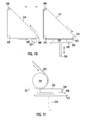
- Figures 1D and 1E illustrate an alternative arrangement in which the build 328 and build pad 330 are held in an upright position on an upright elevator platform 332 and elevator drive 334.
- Reciprocating transport surface 336 is mounted in a triangular configuration about rollers 340, at least one of which is driven. Transport surface 336 picks up build material from a reservoir 337 and gravure roll applicator 338 for transport to the build.
- the transport surface 336 shown on the left hand side of Figure 1D comprises two sections, a coating section 353 and a continuous portion 351, as shown on the right hand side of Figure 1D , which may be, for example, a toothed flexible belt for engaging the rollers 340 for driving the coating section in a reciprocating manner.
- Figure 1E further illustrates contact of the coating section 353 of the transport surface with the build 328 and shows that the roller 340 at the leading edge of the transport surface pushes the transport surface into contact with the build surface, which is the case whether the reciprocating transport surface is in the configuration of Figure 1A or 1D or the other embodiments illustrated hereinafter. Either or both wheels 340 could be driven or another mechanism used, although not necessarily with equivalent results.
- the first roller 340 to encounter the build platform and build surface is generally rigid to set the build material thickness.
- the coating belt illustrated in Figures 1A through 1E and elsewhere throughout the drawings normally is a film of sufficient strength for reciprocating travel and that provides a surface for readily picking up build material and for releasing the build material to the build on the elevator platform.
- the belt typically will be a film composed of one or more polymer build materials, such as polypropylene, polycarbonate, fluorinated ethylene propylene, and mixtures and co-polymers thereof.
- PTFE films including Teflon brand films are useful, in part because they release the build material to the build surface well. Regardless of the material used, the belt should be sufficiently transparent to radiation for solid imaging when the belt is placed between the radiation source and the build material.
- the build material normally is a flowable build material for solid imaging that is responsive to the radiation source and can be taken up on a flexible transport film and conveyed by the film to the build in the image plane.
- a wide variety of these build materials is known for stereolithography. If the radiation source is a digital light processor, or "DLP" source, then the build material typically solidifies in response to visible and ultraviolet light and the build material will contain initiators for both these light sources.
- the build material for flexible transport imaging should readily solidify upon exposure to radiation, should have good adherence to the build, and be readily released from the transport surfaces, whether the coating or uncoating surfaces. Suitable build materials are described in U.S. Patent Application Serial No.
- Such build materials typically include a poly(meth)acrylate compound, a urethane poly(meth)acrylate compound, a polyester poly(meth)acrylate compound, a silicone poly(meth)acrylate compound, and polymerization initiators for visible and UV light.
- Figures 1F and 1G illustrate an alternative to the embodiments of Figures 1A through 1E , which is the inclusion of a second reciprocating transport surface 56, which could be as shown or in the triangular configuration of Figure 1D , for the purpose of removing excess uncured build material from the build surface 26 after irradiation.
- this second transport surface is an alternative uncoating device to the spinning brush 45 shown in Figure 1A .
- the first and second transport surfaces are different surfaces, the first transport surface transporting build material to the build surface in the image plane and the second transport surface removing excess uncured build material from the image plane.
- the reciprocating carriage frame 35 is shown in its right-most position for applying a layer of build material 39 to the build and imaging the build 28 in the manner described for Figure 1A .
- a reciprocating transport belt 36 for coating the build with fresh, uncured build material 39 is mounted on the carriage frame.
- the coating belt picks up build material from a source 37 by contact with a gravure applicator roll 38.
- the build material source and gravure applicator roll are also mounted on the carriage.
- the belt rotates about roller wheel 40 to the left as indicated by the rotational arrows to pick up the solid imaging build material on the belt from the source and deposit the build material on the build surface 26.
- FIG 1G the frame is shown in its left most position for removing excess uncured build material on the build after imaging and before application of a fresh layer of uncured build material to the previously cured layer. Excess uncured build material typically remains only about the edges of the build surface after imaging.
- a second reciprocating transport surface, uncoating belt 56 is mounted on the carriage frame 35 and driven about wheels 58, one or both of which may be driven or another drive mechanism chosen. Unlike the coating belt wheels, the uncoating belt wheel 58 that first contacts the uncoating belt with the build surface is somewhat flexible and resilient to press the belt into the build to remove uncured build material to the uncoating belt.
- the combination of the reciprocating carriage moving to the left and the reciprocating uncoating belt rotating to the right reduces relative motion between the build surface and the belt.
- the uncoating belt can dab the build surface multiple times if necessary by moving the part away from the uncoating belt and moving the uncoating belt to a clean position and lowering the moving part back to contact the uncoating belt.
- the uncoating belt provides a porous surface for take-up and release of uncured build material.
- the uncoating belt may typically be an absorbent web selected from cotton or paper or nonwoven thermoplastic polymers.
- the uncoating belt should be sufficiently structured to stand up to reciprocating service on the drive mechanism for the belt and dabbing of the build to remove uncured build material.
- the uncoating belt readily receives and retains the build material and yet is sufficiently porous to release the uncured build material for disposal or recycling. After removing uncured build material from the build, the uncoating belt transports the excess uncured build material 59 ( Figure IF) away from the image plane for disposal or reuse.
- the reciprocating carriage 35 moves to the right to transport the uncoating belt 56, loaded with uncured build material 59, to remove the uncured build material from the belt.
- Shown in Figures 1F and 1G is a source of pressurized fluid, such as an air knife 62 mounted in a fixed position with respect to the carriage 35 to propel from the uncoating belt and into a receptacle 64 that is mounted on the carriage frame the excess uncured build material removed by the uncoating belt from the build surface.
- the belt moves to the right over the receptacle as shown by the rotational arrows to encounter pressurized air over the extent of excess uncured build material.
- the elevator platform 32 moves the build 28 incrementally to keep the build surface 26 in the image plane for picking up a layer of fresh build material 39 from coating belt 36 ( Figure 1F ), for imaging of the fresh layer from the radiation source 22, and for removal of uncured build material 59 by the uncoating belt 56 ( Figure 1G ).
- the belts move in the opposite direction at a controlled speed to preclude relative motion between the build surface and the belt.
- the belts are reciprocated in the opposite direction from the carriage when the carriage removes either the coating belt or the uncoating belt from the build. Reducing relative motion between the belt and the build surface substantially eliminates entrapment of air in the fresh build material layer laid down by the coating belt and avoids breaking delicate features of the build by both the coating and uncoating belts.
- Figure 1H illustrates in an enlarged view the coating belt of Figure 1G out of contact with the build and reciprocated left.
- the belt moves in the direction indicated by the arrows and remains in contact with the gravure roll 38. It is immaterial to the operation of the apparatus that the belt is coated with build material 39 upon reciprocating out of contact with the build.
- Image plane supporting plate 42 and its elevator mechanism 43 are also mounted on the carriage and are lowered during belt travel.
- the coating belt comprises a transport section 53 connected to form a continuous loop by straps 51, which may be, or example flexible toothed belts. These two sections form the coating belt 36 of the prior figures as a bilaterally endless surface, similar to coating belt 336 of Figures 1D and 1E .
- the reciprocating carriage has been moved to its right-most position, which in the embodiment illustrated is a coating position.
- the reciprocating carriage aligns the coating belt with the build surface in the image plane.
- the gravure wheel rotates clockwise, engaging the coating belt and applying a layer of build material to the portion of the coating belt surface that contacts the build surface on the build platform, in accordance with step 66 ( Figure 1J ).
- the carriage moves right and the coating belt moves left at a controlled speed to bring the coating belt into the image plane, step 68, and preclude relative motion of the coating belt at the image plane.
- step 70 the imager irradiates the image plane with focused radiation, step 72, to solidify the build material, thereby creating a new layer of the solid build.
- the coating belt rotates in the opposite direction as the carriage moves to the left to remove the uncured portion of the coating of build material from the build area and to peel the cured portion of the build material from the belt and to remove the belt out of the image plane, in accordance with step 74. Moving the carriage to the left also brings the uncoating belt into contact with the freshly imaged layer, in accordance with step 76.
- the reciprocating carriage has been moved to its leftmost position into an uncoating position.
- the reciprocating carriage aligns the uncoating belt with the image plane.
- the belt contacts the build surface at the image plane and removes uncured build material from the previous coating operation, in accordance with step 78.
- the carriage moves left and the uncoating belt moves right at a controlled speed to preclude relative motion of the uncoating belt at the image plane, as previously explained, to preclude damage to delicate build structures.
- the uncoating belt turns in the opposite direction and the carriage reciprocates to the right, as shown in Figure 1F to move the uncoating belt out of the image plane and to complete the cycle, step 80.
- the uncoating belt is moved across the air knife which provides pressurized fluid, typically air, to dislodge and push uncured build material through the uncoating web to a reservoir below, step 82.
- Control systems provide programmable control to enable the sequence of building steps to take place, including controlling the elevator position, coating of the belt, reciprocation of the belts, application of the coating to the build pad, imaging the build, reciprocation of the carriage, removal of uncured build material, and temperature.
- a separate enclosure provides the control system components external of an enclosure for the carriage and elevator components.
- An operator's station will typically include a PC for programmable and automated operation.
- Figure 2 illustrates an embodiment similar to that of Figures 1F and 1G modified for semi-continuous operation.
- the build pad is a continuous belt 130 rather than the discreet build pad 30 of the embodiment of Figures 1F and 1G .
- the other aspects of the apparatus as illustrated are the same as those of Figures 1F and 1G , although is should be recognized the spinning brush of Figure 1A or the transport configuration of Figure 1D could be used.
- the semi-continuous embodiment is not limited to the apparatus of the embodiment of Figures 1F and 1G and could be applied to the other embodiments within the scope of this detailed description.
- the continuous belt build pad 130 is oriented perpendicular to the travel of the reciprocating carriage 35 that contains the coating and uncoating belts 36 and 56, respectively.
- the continuous belt 130 seen in section at 130' at the image plane, travels over the image plane in an indexing fashion, indexing forward as each build is completed to provide a fresh platform for each new build.
- the continuous belt build pad 130 can comprise any suitable material that is strong enough to withstand tension, suitably grips the build during the layer-by-layer build process, and provides for ready release of the completed build from the belt.
- One such suitable material is Mylar.
- the continuous belt platform 130 is provided by a supply roll 130' and a take-up roll 130".
- the continuous belt travels from the supply roll over the elevator platform 32 between the elevator platform and the build 28 and can be held in place on the elevator by tension or through the use of vacuum between the elevator platform and the continuous belt.
- the continuous belt 130 is stationary during a build and indexes forward toward the take-up roll to remove the completed builds 128 from the image plane and for placement of a fresh section of build pad 130 over the elevator at the image plane.
- completed builds 128' are removed and placed in a receptacle 136 for further processing or use in manufacturing, as needed.
- completed builds 128' are further cured beyond the green condition to a dry condition or even to a full cure, using suitable light sources, such as UV bulb 61 and reflector 63.
- Figure 2B illustrates the steps of the method of the aspect of the semi-continuous embodiment illustrated in Figures 2 and 2A .
- a clean build is completed on the continuous belt build pad in the image plane in accordance with step 188.
- the belt indexes forward to move the build pad and build out of the image plane and to place a fresh build pad section of the belt in the image plane, in accordance with step 190.
- steps 188 and 190 are repeated for semi-continuous clean build production, step 192.
- One advantage of the semi-continuous embodiment is that the clean green builds can be fully cured semi-continuously and integral to the build process.
- semi-continuous production results in dry builds.
- the semi-continuous aspects of the embodiment of Figures 2 and 2A can also provide additional stages in a semi-continuous fashion. These additional stages can provide additional curing of green builds using ultraviolet lamp assemblies to produce fully cured builds. Additional chemical treatments can be incorporated, if desired, as may be useful in the production of hearing aids.
- the solid imaging apparatus and method of the invention can even be incorporated into and become an integral part of a manufacturing process. For example, orthodontic devices typically are created over molds that are produced by solid imaging. With the practice of the semi-continuous embodiment of the invention, clean molds produced by solid imaging can be fully cured and then enter a molding station for production of the orthodontic devices on a semi-continuous basis.
- FIG. 2B illustrates broadly the additional steps of the method in which the semi-continuous embodiment of the invention is useful.
- a build is prepared on the belt platform, as discussed, and indexed forward.
- Each build is fully cured on the indexing continuous build platform after removal of the build from the image plane, in accordance with step 194.
- the belt can be integrated with a downstream manufacturing process to transport the fully cured builds into or through the process.
- the fully cured builds are removed from the belt platform, as recited in step 198.
- Figure 3 illustrates a second semi-continuous embodiment of the invention adapted for automatic removal and replacement of discrete build platforms from the apparatus illustrated in Figures 1G and 1H .
- the other aspects of the apparatus as illustrated in Figure 3 are the same as those of Figure 1F , although the optional image plane supporting plate 42 and drive 43 ( Figure IF) are not illustrated.
- the semi-continuous embodiment of Figure 3 is not limited to the apparatus of the embodiment of Figure 1G and could be applied to the other embodiments within the scope of this description.
- the elevator 34 and elevator platform 32 are shown raised well above coating belt 36.
- the previous build will have been completed and the build and the build platform on which the build would have been supported have been removed. A new build on a fresh platform has not yet started.
- the reciprocating carriage 35, the coating and uncoating belts 36 and 56, respectively, are stationary.
- a stack of discrete build platforms 230 is provided in a dispenser 230' and a fresh build platform 230" is being removed from the dispenser and transmitted to the elevator platform 32.
- these build platforms would be removed and replaced, from the dispenser to the elevator and from the elevator with a completed build, with conventional pick and place systems (not shown) adapted for use with the apparatus of the invention.
- the build platform 230" is secured to the elevator platform and aligned with the image that is produced by the imager 22.
- FIG. 3A The steps of the method for practice of the embodiment illustrated in Figure 3 are illustrated in Figure 3A .
- a complete and clean build is completed on one of the discrete build platforms in accordance with step 288.
- a pick and place system or other suitable system removes the build and the build platform in accordance with step 289.
- the system then secures a fresh build platform on the elevator platform and aligns the build platform with the imager in the image plane, step 290.
- steps 288, 289, and 290 are repeated, step 292, for semi-continuous clean build production.
- the clean green build can be removed from the build platform on which it was made, or the build can be fully cured on the platform, step 294, and then removed from the build pad, step 298.
- Steps 294 and 298 can be performed, if desired, after step 288 and while the build 28 and build pad 30 are still in place on the elevator platform 32 ( Figure 3 ), or after removal in accordance with step 289.
- Figure 4 illustrates a longitudinal plan view of an embodiment of the apparatus of the invention capable of using build material from more than one source.
- the embodiment of Figure 4 can provide clean builds made of more than one build material.
- This embodiment provides two endless reciprocating coating belts 336 and 336' in tandem with an intervening indexable and reciprocatable uncoating belt 356, each of which is mounted to a carriage 335 for reciprocating movement of the assembly of coating and uncoating belts over a build platform 332 on which is mounted a build pad 330.
- the build pad 330 is elevated by a driver 334 and elevator platform 332.
- the build is imaged by imager 322.
- Gravure applicator rolls 338, 338' and reservoirs 337, 337' are fixed on a supporting frame 350 and the coating belts travel over them as the carriage reciprocates back and forth.
- the gravure rolls and reservoirs are not mounted on and do not reciprocate with the carriage as in Figures 1A and 1F .
- Other aspects of the Figure 4 embodiment include heating of the apparatus in an enclosure 349.
- the materials used for the belts and composition of the build materials are similar to those discussed above.
- the combination of the reciprocating carriage moving in one direction and the reciprocating coating and uncoating belts moving in the opposite direction reduces relative motion between the build surface and the belts and reduces the possibility of air entrapment in the fresh build material layer applied to the build surface and breakage of delicate build structures. While there are several similarities between the previous embodiments and that of Figure 4 , it should be noted that the build is not upside down in the embodiment of Figure 4 and following.
- the coating belts 336 and 336' are arranged in triangles about three rollers, which may be tensioning or drive rollers as needed.
- the three rollers 340 are associated with coating belt 334.
- Rollers 340' are associated with coating belt 336'.
- the coating belts each could also be arranged about two rollers 40 in the manner illustrated in Figure 1A , if desired. As in the embodiment of Figures 1A and 1E , the leading roller to encounter the build surface on the build platform is sufficiently rigid to set the build material thickness.
- the coating belts provide alternate coating of a build 328 from separate sources of build material, reservoirs 337 and 337', respectively. These separate sources can contain the same or different build materials. Reservoir sources 337 and 337'supply build material to gravure rolls 338 and 338', respectively, in each reservoir, which gravure rolls transfer build material to the coating belts for transport to the image plane similar to the way in which this is accomplished and described with reference to Figure 1A .
- the uncoating belt 356 is a continuous indexable and reciprocatable belt supplied from a supply roll 357 over drive and tensioning rollers 358 to a takeup roller 359.
- Rollers 358 at the bottom are each the first to contact the uncoating belt with the build surface, depending on whether the carriage is reciprocating right or left, and so both of these rollers are somewhat flexible and resilient to press the belt into the build to remove uncured build material to the uncoating belt.
- Fresh uncoating belt can be provided as needed by indexing the belt from the supply to the takeup roller.
- Figure 4 illustrates a reflector 361 and UV bulb 363 for curing the uncured build material on the uncoat belt as it winds onto the takeup roll for disposal of the used belt.
- the build material recovery system and uncoating belt configuration of Figures 1E and 1F can be employed, adding a second coating belt on the opposite side of the uncoating belt from the first coating belt, with an air knife or other suitable apparatus to knock the build material out of the web of the uncoating belt. It should be recognized that if the sources of build material 337, 337' are ink jet sources, then an uncoating device 356 should be unnecessary in either of these configurations.
- the first coating belt 336 receives a layer of coating material from source 337 via contact with a gravure roll 338.
- the belt moves to the image plane and transfers the build material to the surface 326 of build 328 in the image plane defined by imager 322.
- the imager 322 supplies focused solid imaging radiation 324 to harden the build material.
- the carriage, including coating belts 336 and 336' and intervening uncoating belt, web 356, will index left, moving coating belt 336 out of the image plane and placing the uncoating belt 356 in contact with the surface of the hardened build to remove any excess uncured build material.
- the carriage continues to index left to move the uncoating belt out of the image plane.
- the uncoating belt may be indexed forward to expose fresh web.
- the uncured coated portion of uncoating web 356 can be cured at this time by flash exposure for eventual disposal.
- the second coating belt 336' picks up build material from source 337' via contact with a gravure roll 338'.
- the carriage places the second coating belt 336' over the build platform to transfer build material for imaging onto the build on the build pad.
- the carriage then moves the coating and uncoating stages to the right to bring the uncoating web 356 again into contact with the build for uncoating. Repeating all of these steps produces a build.
- Figure 5 is a longitudinal plan view of a similar embodiment of the apparatus of Figure 4 and having larger supply and take-up rolls of uncoating media, not shown, located remote from the coating and uncoating carriage so as not to interfere with the imager 322 during reciprocation of the coating and uncoating stations.
- the supply and take-up rolls in the embodiment of Figure 5 are provided detached from the moving assembly.
- Web turning rollers may be provided to direct the uncoating belt to the uncoating position from the supply roll and from the uncoating position to the take-up roll.
- Other elements are similar to those of Figure 4 and bear the same numbers; operation is generally as described with respect to Figure 4 .
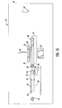
- Figure 6 is a longitudinal schematic plan view of another embodiment of the apparatus similar to that of Figure 4 and designed for use with a single source of build material.
- the apparatus of Figure 6 has a single coating belt 336 that receives solid imaging build material from a fixed reservoir source 337 via a gravure wheel 338 over which the coating belt passes as the carriage reciprocates.
- the build material is then applied layer-by-layer to a build 328 supported by an elevator drive 334, elevator platform 332, and build pad 330.
- An imager 322 exposes each layer of build material to radiation 324 to solidify the layer.
- a supply roll 357 and a take-up roll 359 provide fresh uncoating web 356 for removing uncured build material from the build between application of fresh layers.
- the build material removed from the build part is solidified by a flash exposure radiation source, a UV lamp 361 and reflector 363, before it is wound onto the take-up roll.
- the coating and uncoating belts are contained in enclosure 349 and can be heated so that the benefits of heating the build material for take up on the coating belt and application to the build can be realized as discussed above. Reciprocating operation of the device is as described above with respect to Figure 4 , although without the second coater.
- Figure 7 is a top plan view of the embodiment of an apparatus shown in Figure 4 , with the addition of a second apparatus in parallel for applying a multiplicity of build materials to a single build.
- the apparatus has first and second reciprocating carriages in parallel.
- the carriages are generally the same as that of Figure 4 , only one of which is disposed over the build platform at one time.
- the entire assembly of first and second carriages reciprocates perpendicular to the reciprocation of the individual carriage over the build platform and pad to place first one reciprocating carriage and then a second carriage in the image plane over the build platform and pad, as indicated by the directional arrows.
- First and second reciprocating carriages have two coating belts 336, 336' and 436, 436,' respectively, and an uncoating belt 356 and 456, respectively.
- the arrow indicating left and right motion indicates reciprocation of the first carriage containing belts 336, 356, 336' over the build platform 332.
- the second carriage assembly having belts 436, 456, 436,' is out of service until the coating and uncoating operation of the first carriage assembly is completed.
- the first carriage assembly has completed its layers, cured by exposure to radiation source 322
- the first carriage assembly moves in the direction indicated by the vertical arrow to placement out of service and to bring the second carriage assembly into service in alignment with the build platform.
- the second carriage assembly moves in the direction indicated by the vertical arrow to placement out of service and to bring the second carriage assembly into service in alignment with the build pad 330 until the build 328 is completed.
- the assembly of Figure 7 is capable of putting down up to four separate build materials.
- One carriage may be used to provide the supports while another provides the build product.
- complex structures having layers of various build materials can be created such as are used for biological structures. It should be recognized that by including additional carriages, the embodiment of Figure 7 can be extended to a third or fourth carriage or even more to increase the number and kind of build materials used in the solid imaging process.
- Figures 8, 9, and 10 depict different views of a conventional digital light processor imager 722 of the kind that can be used as an imager providing focused radiation in the practice of any of the embodiments shown in Figures 1A through 7 .
- Figure 8 shows the imager from a top plan view with the optical axis 700 centered on the image 702 produced by the imager.
- Figure 9 shows the imager from a side plan view supported on a surface 704 by pads 706 and demonstrates that the image is offset above the optical axis.
- Figure 10 shows the imager from a rear plan view and that the image is offset to the right and above the optical axis.
- the imagers include UV projectors, scanning laser systems as used with stereolithography, LCD's (liquid crystal diodes), LCoS's (liquid crystal on silicon), LED's (light emitting diodes), or DLP (digital light processing) projectors.
- the imager is a DLP projector.
- Commonly available imagers typically are limited to an image area of 1024 x 768 pixels.
- Higher resolution imagers with higher micromirror density typically have an image area of 1400 x 1050 pixels and produce images with dimensions about 37% larger than the smaller imagers.
- DLP projectors typically require modified optics to display both UV and visible light wavelengths, establish a desired focal length based on the arrangement of the flexible transport solid imaging carriage system, and to adjust the light intensity based on the material used.
- One such modified DLP projector incorporates a DMD (digital micro-mirror device) array and has a lamp and a nine-element projection lens imaging radiation from the lamp over a spectral range suitable for solid imaging, including from about 350 to 450 nm in focus at a projection distance of 400 mm over an image area of 9 x 6.75 inches (22.9 x 17.4 cm). The image is 1024 pixels wide and 768 pixels high.
- the DLP projector may include a UV/IR filter to remove radiation from the lamp outside the desired spectral range.
- An illumination lens may be used to uniformly distribute radiation from the lamp across the projection lens.
- a UV-enhanced light pipe interconnecting the lamp and the illumination lens and UV-enhanced mirrors in radiation-directing communication with the illumination lens and projection lens
- the aforementioned 10.24 inch by 7.68 inch area would look like it had a substantially greater effective resolution than merely 100 dpi. Larger build platforms can also be utilized and larger objects can be fabricated.
- a digital light projector controls a set of very small mirrors to reflect light into related pixels.
- the light intensity K of each projected pixel in the image plane can vary from 0 (black) to 1 (white) with different gray scale levels from 0 to 255.
- One suitable range of gray scale levels is from about 60 to about 255.
- Another suitable range of gray scale levels is from about 100 to about 255.
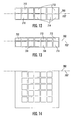
- the inherent characteristic of commercial digital light projectors that the pixels in an image are fuzzy or have slight image blurring results in the light intensity overlapping neighboring pixels.
- This light intensity distribution can be approximated as a Gaussian distribution for purposes of further explanation, but in actuality the light distribution can take many different forms.
- the light intensity K at a point (x, y) is actually the sum of the light intensity contributions of all the neighboring pixels to the point (x, y).
- the light intensity at point (x,y) is the blended result of all of the light intensities of point (x, y)'s neighboring pixels.
- the light intensity of a pixel decreases the further it is away from the center of the pixel.
- the light intensity of a pixel is spread to all of its neighboring pixels. Where the point is in a boundary pixel forming the edge or wall of an object, there will be fewer neighboring pixels: 3 neighboring pixels for a point located in a corner wall pixel and 5 neighboring pixels for a point located in an edge or wall pixel apart from a corner.
- Controlling the exposure of an image area can be achieved by controlling certain exposure parameters.
- Exposure Intensity of the radiation x Time of exposure. This relationship is utilized in controlling exposure parameters.
- One parameter is controlling the illumination time of each pixel within the plane that constitutes the cross-section of a three-dimensional object being built.
- another parameter to control the level of exposure can be varying the light intensity levels, for example by varying the gray scale levels while holding the exposure time constant for all boundary pixels.
- a third parameter is varying the width of the light intensity of the projected pixels. This can be achieved by varying the degree of focus of the projected pixels. This parameter can vary at different locations across the image area.
- An individual projector can be characterized for its pixel intensity width in both the x and y planes as a function of the pixel location by measuring the projected intensity with a digital camera at selected pixels in the image area. This information can then be stored in the solid imaging apparatus to be employed to obtain optimal image performance across the image plane and accurate control of the polymerization boundary in the object being formed.
- a fourth additional parameter that may be controlled is the light intensity versus the age of the lamp in the projector.
- Calibration is achieved by adjusting the different light intensities for the pixel at point (x, y) and its eight neighboring pixels so that the desired accumulated light intensity K is sufficient to solidify the solidifiable photopolymer build material at that point based on the time of illumination of each pixel in the image area forming an object cross-section.
- the accumulated light intensity K equals or exceeds the critical energy Ec needed to solidify the solidifiable photopolymer build material, such as a liquid resin formulation, that build material will solidify and add to the geometry of the object being formed. Where the accumulated light intensity is less than the critical energy Ec, the build material will remain in the non-solidified or liquid state.
- the critical energy Ec is much less that the energy used to expose the body of the layer within the boundary, perhaps 20% or less.
- the Ec for typical resins employed in apparatus of the invention is normally about 10 to 12% of the layer exposure energy employed.
- the width of the region that is solidified varies according to the light intensity of the edge pixel. Since the light intensity from a pixel varies with gray scale, the polymerization of the solidifiable build material forming the edge or border of a region can be controlled by varying the gray scale of the border pixels.
- Varying exposure intensity levels and pixel intensity width or the degree of projected pixel focus creates slight image blurring and affects the amount of light energy delivered to boundary pixels to control the polymerization boundary of the solidifiable photopolymer build material to thereby define the effective location of the edge or boundary of a feature in a boundary pixel of an object with sub-pixel resolution.
- Varying the intensity exposure levels is achieved by varying the illumination or exposure time and/or the gray scale exposure levels. This technique achieves much higher image boundary resolution than is present in just the pixel resolution.
- a projected image is a two-dimensional image with edges in the x and y directions.
- the fabricated object extends in the z direction, or the third dimension.
- the invention achieves edge smoothness in the projected image in individual two-dimensional cross-sectional image projections.
- each individual two-dimensional cross-sectional image projection polymerizes the solidifiable photopolymer build material, a solid layer is formed corresponding to the exposed projected pixel areas on the solidifiable photopolymer build material.
- Adhering or summing superimposed multiple cross-sectional layers one to another in a build process the present invention forms a three-dimensional object with smooth walls that are formed from the plurality of adhered smooth edges in the individual cross-sectional layers.
- digital data for the three dimensional object to be built is sent to the solid imaging system.
- This is preferably from a CAD station (not shown) that converts the CAD data to a suitable digital layer data format and feeds it to a computer control system or host computer (also not shown) where the object data is manipulated to optimize the data via an algorithm to provide on/off instructions for the digital light projector.
- this digital data can be received by the solid imaging systems by digitizing a physical part or from pattern files.
- the solid imaging layer data attained by the CAD data or by digitizing a physical part or sometimes from pattern fills is preferably processed by the host computer utilizing a slicing program to create cross-sectional data representative of the cross-sectional layers of the object to be built.
- the solid imaging layer data obtained from pattern data is sometimes not sliced, but patterns are directly utilized as bitmap cross-sections. These steps of the present invention are conducted in the same fashion as in standard stereolithography processes.
- the slice data obtained from the slicing program is converted into bit map data.
- the host computer uses a gray scale software program, the host computer calculates the gray scale exposure levels required to control the polymerization boundary of the solidifiable photopolymer build material when the build material is exposed.
- a microprocessor controller or computer in the solid imaging apparatus receives the bit map input of the object to be formed. An algorithm is then applied to the bit mapped cross-sectional data by the controller or computer in the solid imaging apparatus to create the instructions for a controller, such as a microchip, in the digital light projector.
- the digital light projector has previously been characterized for its focus of the projected light pixels by observing the degree of focus of pixels across the image area (or plane).
- the projector has also been characterized for its light intensity distribution by the use of a radiometer to record light intensity at selected pixel locations on the image area and the focus and illumination time have been adjusted as needed.
- the illumination time is adjusted based on the light intensity, age of the lamp in the digital light projector, and the particular solidifiable photopolymer build material to be utilized.
- a radiation transparent build material carrier delivers the solidifiable photopolymer build material from a supply reservoir or cartridge to the imaging area.
- the imaging area is supported by the support platform that is movably mounted to the frame of the solid imaging apparatus to extend and retract the support platform on which the solidifiable photopolymer build material is polymerized and formed into a three-dimensional object.
- the digital light projector illuminates selected pixels in the desired illumination pattern at desired exposure levels in the image area within the boundary of the three-dimensional object by projecting an image representative of the bit mapped cross-sectional data in the cross-section being formed.
- the desired exposure levels are obtained by having characterized the digital light projector for one or more of the previously discussed exposure parameters and adjusted the exposure levels as needed in response to the characterization.
- the desired exposure levels from the digital light projector in the image area permit the projected image to selectively solidify the photopolymer build material and control the polymerization boundary of the photopolymer build material in the projected pixilated image through the application of different exposure parameters to different areas of the image plane.
- the build platform is then moved out of contact with the radiation transparent build material carrier to prepare for the receipt of fresh or uncured solidifiable photopolymer build material prior to the next exposure.
- the steps of delivering the solidifiable photopolymer build material, illuminating the image area on the support platform and repositioning the support platform to receive a fresh supply of solidifiable photopolymer build material is repeated for each cross-sectional layer until the three-dimensional object is completed.
- the algorithm selects pixels for a higher gray scale value exposure or illumination that have a larger portion of the object's feature within a particular pixel.
- the gray scale value K of a pixel is set according to the area of the pixel that is inside the part or feature.
- a gray scale value is needed for boundary pixels and their neighboring pixels since the ratio is 1 for pixels inside the part or feature and 0 for pixels outside.
- the value of the area of the portion of a boundary pixel that is inside the part or feature is based on super-sampling and approximates the value of the area A' of the portion of a pixel that is inside the part or feature. This super-sampling approach is suitable for use with an image-based slicing algorithm.
- the algorithm divides a boundary pixel, through which some portion of the object's feature passes, into a set of sub-pixels Pij in a k x k matrix or subdivision of the sub-pixels Pij.
- the algorithm samples each of the sub-pixels Pij at its center to determine if it is covered by some portion of the object's feature.
- the total area of those sub-pixels Pij covered by or within some portion of the object's features approximates the area A' of the portion of the divided pixel that is inside the object's feature.
- the boundary resolution of an object built is determined by the number of subdivisions described above forming the k x k matrix or subdivision. For example, a 4x4 matrix will have 16 different gray scale values and the boundary resolution determined by Pixel Size/4. Similarly, for an 8x8 matrix there will be 64 different gray scale values and the boundary resolution determined by Pixel Size/8.
- An alternative algorithmic approach to the super-sampling technique just discussed for instructing which pixels for the projector to illuminate can be based on boundary area calculations.
- the area calculations within the boundaries of the projected object or feature within each pixel use the actual or closely approximated boundary segments to create distinct geometric shapes within the boundaries of each pixel.
- the algorithm will calculate the exact or approximate areas of each geometric shape to be illuminated within the boundary segment or segments passing through each pixel and sum the areas to generate an exact or nearly exact area within the boundary segment or segments of the object or feature being projected in each cross-section of the object.
- the building area of a solid imaging device can be increased by increasing the number of imagers.
- the invention includes solid imaging in which two or more imagers are aligned for use as an imager assembly for increasing the image area. Each of these imagers can be multiplied in a precisely aligned array to produce larger image areas without increasing minimum feature size or reducing radiation power density.
- the imagers are individually characterized prior to the alignment procedure using an array of digital cameras.
- the intensity distribution of each imager is characterized by using a radiometer probe.
- One suitable camera array is a 16 camera array arranged with 4 rows of cameras having 4 cameras per row.
- Suitable cameras include black and white model IV-BWCAM2EX cameras with Euresys Picolo Pro 3 series frame grabbers.
- the set of multiple imagers is characterized using another digital camera array of 9 cameras to align the images produced by the imagers and to measure the pixel blending characteristics along the seams between the image areas. Pixel blending characteristics typically are much different along opposite sides of the seams.
- Figure 11 shows in rear plan view an example of an array of multiple imagers 722, 722', 722", and 722'” aligned for use in solid imaging.
- the projection area of each imager designated separately as 702, 702', 702", and 702'" corresponds to a quadrant of the combined projection area.
- Nine cameras 710 are focused on the seams between the individual imager projection areas to observe the intensity and alignment of the imagers in the imager array.
- Figures 12, 13, and 14 depict test patterns used to align multiple imagers for use in an imager array.
- Figure 12 is a subset of pixels 712, 714 at the boundary of two imager projection areas 702 and 702' with the two imagers 722 and 722' aligned.
- Figure 13 is a subset of pixels 712, 714 at the boundary of two imager projection areas 702, 702' with the two imagers overlapping by a 1 ⁇ 2 pixel.
- Figure 14 is a 5 pixel x 5 pixel pattern showing the seam 702/702' of an image used to characterize an imager 722'.
- the imagers can be aligned by establishing a 2 x 2 pixel checkerboard test pattern imaged with each imager and viewing the seams with the 9 cameras positioned on the seams.
- the imager positions are adjusted to obtain the best match of test patterns along each of the seams. Because of pincushion or barrel distortion, it may not be possible to exactly match the patterns, so some overlap of 1/2 pixel, 1 pixel, or more may be required to insure the imagers cover the entire area of the test pattern with no gaps. Maximum overlap is typically about 1 pixel.
- the imagers may need to be adjusted to account for variation in intensity between the imagers, which may be measured by a radiometer probe.
- the magnification of each imager may then be adjusted by moving the imager slightly closer or farther away from the target or by adjusting the zoom lens, and the magnifications are adjusted so that, as closely as possible, the pixels completely line up along the seams.
- the solid imaging build material only has two possible states: the material can either be cured or it can be uncured.
- the energy on a given pixel is not only imparted by the exposure of that pixel but also by the exposure of neighboring pixels.
- the solidification of the solid imaging build material at a given pixel location on the image plane is the result of the accumulated exposure of that pixel and its neighbors. Accumulated exposure may be used advantageously to enhance the resolution of the borders of the projected image, which is discussed in U.S. Patent Application No. 11/468,090, filed August 29, 2006 and entitled "Improved Wall Smoothness, Feature Accuracy and Resolution in Projected Images via Exposure Levels in Solid Imaging," the contents of which are incorporated herein by reference in their entirety.
- Accumulated exposure has further implications when working with multiple imagers. Specifically, when a portion of the image falls within the overlapping projection area of two or more imagers, exposure levels near a portion of the area to be solidified may be multiplied. In other words, while the exposure level produced by a single imager may not be sufficient to cure the build material at a given area, the exposure of that area by multiple imagers may cumulatively provide enough energy to solidify the build material.
- this method provides that for each imager at each camera position 710 at the seams, a 5 pixel x 5 pixel pattern is imaged as shown in Figure 14 for seam 702/702'. Sequentially, first the intensities of the outside columns and then the intensities of the outside rows of the patterns are reduced by changing the gray scale over a range from 255 to 0. At each change in gray scale the intensity profile from the camera is recorded. The data from these recorded profiles is manipulated and compared to the threshold exposure for the solidifiable photopolymer build material to be used to determine the relationship between the border position and gray scale.
- Different gray scales may be required for two imagers for a given border position that crosses a seam.
- the gray scale values of the border pixels is calculated and the correct gray scale is applied to correct positions of the borders across the seams.
- the gray scale versus border position calibration is interpolated between the cameras. If the interpolation is not precise enough, then intermediate camera positions are used or the cameras are moved along the seam, and more data is recorded to improve the precision.
- the border position could be corrected with exposure time or a combination of exposure time and gray scale.
- Exposure rules are established for the cases where pixels overlap. For example, if pixels overlap, then each of the pixel intensities is reduced by half the percentage of overlap with gray scale adjustments (in addition to any gray scale adjustment for the correct border position). There may be a slight imaging artifact remaining on the seam; the visual effect of this artifact can be reduced by adding a small random offset to the border position data every layer.
- a controller may be provided to control the exposure at the seams and for segmenting the projected image by the imager that produced the image segment.
- control functions may be provided for automated operation of the apparatus, including the coating and uncoating functions, elevator function, imager function, the embodiments having multiple imagers for increased build size, and others. These controllers are not illustrated and it should be recognized that these control functions will normally be combined into a single controller element.
- Figures 15A, 15B , and 15C further illustrate the importance of determining the position of an image border for each imager in an imager array where the imagers overlap.
- the figures show two imagers: imager A on the left and imager B on the right, along a 45 degree border area. The image is shown in these figures in dark outline.
- Border 750 corresponds to that of Figure 15A ; border 752 to that of Figure 15B ; and border 754 to that of Figure 15C .
- the individual squares represent pixels of the imager indicated, each in a 5 X 5 array, and the imagers overlap along the centrally located pixels by about 1 pixel to create a total array of 9 x 5 pixels. Shading indicates the degree of illumination of the individual pixel. The unshaded pixels are full on; the heavily shaded pixels are full off; the lightly shaded pixels are in between, neither fully on or fully off.
- Figure 15A illustrates the situation where the gray scale for imager A has been characterized, and that imager A gray scale characterization has been applied to imager B to set the border position.
- imager B tends to displace the image up, which is to say that imager B supplies more light to the pixels at the border position than does imager A.
- the effect can be seen in the border position at the point 751 where the image crosses from the region of imager A to that of imager B.
- the image border displaces up in the imager B-only region, which is to say, more build material corresponding to the imager B pixel solidifies since there is more available light (the imager B pixels are more fully on at the imager A gray scale adjustment).
- Figure 15B shows how the application of independent gray scale characterization for each imager in an imager array corrects for the image displacement seen in Figure 15A .
- the image border location 752 is matched to each imager so that the border location is known with respect to gray scale. Gray scale adjustments can then be used where the images are stitched together from separate imagers. If imager B is correctly characterized, then the gray scale exposure reduces and matches that of imager A's adjustment. The 45 degree border is correctly located.
- Figure 15C illustrates the prior art in which no gray scale adjustment is made at the border and shows the image of Figure 15A , which is still displaced up where the image crosses into the more fully on area of imager B at 755, and has also been displaced to the left as a result of no adjustment having been made for the imager A brightness at the edges of the image, even further displacing the imager border from the desired location.
- Figures 15A, 15B , and 15C illustrate only a small portion of the typical total area of an image, at a small section of border, for simplicity.
- the total illuminated pixel area is much larger and additional steps are taken to ensure an accurate build.
- the build material may shrink when cured.
- FIG 16A A summary of the basic steps of the method for aligning the imagers for use in the array is illustrated in Figure 16A .
- the image areas of each imager in the array are aligned along the edges of each image, in accordance with step 730.
- the image areas produced by each imager are imaged on a target divided into areas corresponding to the image from each imager.
- the position of each imager is precisely adjusted until its image precisely fills its respective target.
- the imagers are precisely moved until the best match up of the test patterns is achieved along each of the seams, producing seams between image areas with pixel overlap, step 733.
- the nine cameras are positioned along the seams of adjoining images, and the seams are viewed to precisely determine the amount of overlap, step 735.
- One of the overlapping imagers at a seam is selected as dominant for exposing the overlapping image area, step 737.
- the border position of the overlapping pixels is corrected by adjusting the gray scale of the pixels, in accordance with step 739. These steps are repeated for each imager in the array, step 741.
- the array can be used just like a single imager, with the exception that the imaging software must segment the image according to which imager or imagers produce the portion of the image and then apply the exposure rules for the seams.
- the steps of the method for using the multiple-imager array in the context of the invention is illustrated in Figure 16B .
- the build area is imaged with the array of imagers in accordance with step 743.
- the imaging software segments the image depending on the particular imager that produced the segment, step 745.
- the software applies exposure rules for the seams that were developed during the alignment procedure, step 747, to complete the method.
- the multiple-imager array of the invention can be adapted for use in connection with a conventional stereolithography system in which radiation is used to cure layers of build material from a container of build material one layer at a time.
- inventions described above can all be adapted for semi-continuous operation as described in connection with Figures 2 , 2A , 2B , 3 , and 3A .
- Semi-continuous operation is useful in a wide variety of areas. Two areas in particular are the production of hearing aids and the production of molds for orthodontic retaining devices, both of which have been accomplished by solid imaging for some time.
- Figures 17A, 17B, and 17C illustrate another technique, image displacement, for improving resolution by placing borders at the correct position.
- image displacement may require 8 to 10 shifted border exposures to achieve the smoothness and accuracy of the pixel blending method using gray scale adjustment described above.
- Image displacement generally is described in copending and commonly owned US Patent Application Serial No. 11/096,748 filed April 1, 2005 , the contents of which are incorporated by reference herein in their entirety.
- Figure 17A illustrates at 760 a 2 x 3 pixel array from, for example, an imager A, full on.
- Figure 17B illustrates at 762 a 2 x 3 pixel array from, for example, an imager B, the image of which is displaced by one pixel with respect to that of imager A in Figure 17A .
- Figure 17C Via multiple border exposures, the result is that of Figure 17C , illustrating at 764 exposure effectively displaced a subpixel amount, 1 ⁇ 2 pixel in Figure 17C .
- Figure 18A illustrates another embodiment of the invention that does not use an uncoating belt to produce a clean build.
- Figure 18A illustrates ink jet sources 837, 837' of solid imaging build material 839, 839,' all of which can be the same or different materials and which can be used to make a build of multiple build materials, if desired, or to apply a support structure of a different material from the build.
- the amount of material applied is reasonably uniform across the cross-sectional area and at least enough to make up the height at the cross-sectional layer, and ideally not significantly more than this amount.
- the ink jet applicators apply a cross-sectional image of jettable solid imaging material to the first coating belt 836 as the coating belt is advanced counterclockwise as shown by the rotational arrows for positioning a layer of coating material on the belt for transfer to the build platform and flash exposure.
- the system of Figure 18A is configured so that as belt 836 is coated, belt 836' is applying its layer of build material to the build surface in the image plane, rotating counterclockwise as the belt encounters the build surface.
- the coating belts travel on a reciprocating carriage as indicated by the horizontal arrows in Figures 18A and 18B that moves back and forth to alternately coat each belt and to transfer that coated belt to the build surface in the image plane.
- belt 836 rotates clockwise as shown by the directional arrows to orient the build material on the surface of the build and apply the build material to the build in the image plane.
- the coating belts, 836, 836' are operated in a reciprocating manner as indicated by the rotational arrows in Figures 18A and 18B , similar to that of Figure 1E , so as to reduce relative motion between the coating layer and the build and reduce the opportunity for entrapping air or damaging the build.
- the ink jet system produces in response to a control system (not shown) a solid image build material that is configured on the belts in the image to be solidified on the build.
- a control system not shown
- a solid image build material that is configured on the belts in the image to be solidified on the build.
- the apparatus does not require focused radiation from source 822 to solidify selected portions of the wetted surface of a build. Instead, irradiating the entire image plane from a flash exposure source 822 and reflector 822' with suitable radiation for curing, typically UV radiation from a UV lamp, produces the desired solid image layer in the absence of uncured build material.
- suitable radiation for curing typically UV radiation from a UV lamp
- Figures 18C and 18D illustrate sequence views of the extension of the embodiment illustrated in Figures 18A and 18B to multiple coating belt configurations. It should be recognized that additional ink jetters could be added to each belt. Additional coating belts 836" and 836"' have been incorporated into the system. Operation is similar to that of Figures 18A and 18B , the carriage reciprocating and the belts reciprocating to place each coated belt over the build for imaging the build and for flash exposure of the image.
- Figure 18A could be operated with a single belt and inkjetter, although typically two or more, as illustrated in Figures 18A, 18B , 18C, and 18D will be used for efficiency and versatility, even if using only one build material. It should also be recognized that the systems of Figures 18A, 18B , 18C, and 18D , can be ganged similar to that of Figure 7 , with multiple sets of two or more parallel belt systems for multiple materials. The ganged system can also be operated semi-continuously, as described in connection with Figures 2 , 2A , 2B , 3 , and 3A .
- FIG 18E illustrates the method steps for operation of the embodiment of Figures 18A and 18B .
- Reciprocating coating belt 836 rotates counterclockwise, which in this embodiment is the same direction as the direction of carriage travel to the left to place the belt over the ink jetter 837, to pick up build material 839 from source 837, all in accordance with step 866.
- Belt 836 rotates about wheels 840 similar to the manner described above with respect to other embodiments.
- the carriage shifts right and the belt rotates to clockwise as shown in Figure 18B to place the belt 836 and build material 839 in the image plane, step 868, and to transfer the build material to the build surface, step 870, with no relative motion so that air is not entrapped and delicate features are not destroyed.
- Elevator 834 and elevator platform 832 support the build on a build pad 830 in the image plane.
- Radiation source 822 provides a flash exposure of solid imaging radiation to solidify the layer of build material, and typically will be a UV lamp, in accordance with step 872.
- the carriage reciprocates to the left to move belt 836 out of the image plane, step 874 and back into the position shown in Figure 18A for recoating.
- belt 836' operates in the mirror image of belt 836, transferring build material to the image plane while belt 836 picks up build material and picking up build material while belt 836 transfers build material to the image plane.
- the above steps are repeated for the second belt as indicated by the use of primes, and, finally, the steps are all repeated numerous times to complete a build, step 878.
- Figures 19A , 19B , 20A , and 20B illustrate various combinations of the embodiments discussed above.
- Figures 19A and 19B are sequence views of the apparatus of Figure 1E to which has been added one of the image coating belts 836 with an ink jet applicator 837 of Figure 18A .
- the embodiments show first and second transport surfaces, which are a coater and uncoater, respectively, and a third transport surface opposite the second from the first, so that the second transport surface is between the first and second.
- first and second transport surfaces which are a coater and uncoater, respectively
- a third transport surface opposite the second from the first so that the second transport surface is between the first and second.
- Like parts bear the same numbers and operation is similar.
- the carriage applies a coating from coating belt 36 to build 28 which is imaged by imager 22.
- the carriage then moves left to remove excess uncured build material 59 onto uncoating belt 56.
- the carriage then moves further left to apply coating from ink jet imager 837, which images build material onto the imaging belt 836.
- the imager 22 is a focusable imager, which focus is immaterial to curing the image provided by the ink jet build material source 837.
- the focusable imager can be operated for flood exposure by having all the pixels illuminated, or even less than all so long as a sufficient illumination flood is provided.
- the imaging belt 836 should be at the same height as the coating and uncoating belts 36 and 56, respectively, and that a brush 45 ( Figure 1 ) could take the place of an uncoating belt 36 or 56.
- Figures 20A and 20B are similar in operation, substituting instead the right most coater of Figure 4 with the ink jet and image coater of Figure 18A as in Figure 19A . It should be recognized that the operation and identification of the embodiment of the coater/uncoater belt combination shown in Figure 4 applies to Figures 20A and 20B as well.
Applications Claiming Priority (6)
| Application Number | Priority Date | Filing Date | Title |
|---|---|---|---|
| US88525707P | 2007-01-17 | 2007-01-17 | |
| US88525407P | 2007-01-17 | 2007-01-17 | |
| US94961407P | 2007-07-13 | 2007-07-13 | |
| US95611807P | 2007-08-15 | 2007-08-15 | |
| US95605107P | 2007-08-15 | 2007-08-15 | |
| US11/856,455 US7706910B2 (en) | 2007-01-17 | 2007-09-17 | Imager assembly and method for solid imaging |
Publications (3)
| Publication Number | Publication Date |
|---|---|
| EP1946910A2 true EP1946910A2 (de) | 2008-07-23 |
| EP1946910A3 EP1946910A3 (de) | 2010-02-24 |
| EP1946910B1 EP1946910B1 (de) | 2012-03-28 |
Family
ID=39365960
Family Applications (1)
| Application Number | Title | Priority Date | Filing Date |
|---|---|---|---|
| EP08000401A Active EP1946910B1 (de) | 2007-01-17 | 2008-01-10 | Bildanordnung und Verfahren für die feste Bildgebung |
Country Status (3)
| Country | Link |
|---|---|
| US (1) | US7706910B2 (de) |
| EP (1) | EP1946910B1 (de) |
| JP (2) | JP2010516498A (de) |
Cited By (11)
| Publication number | Priority date | Publication date | Assignee | Title |
|---|---|---|---|---|
| WO2011084578A1 (en) * | 2009-12-17 | 2011-07-14 | Dsm Ip Assets, B.V. | Substrate-based additive fabrication process |
| WO2015167335A1 (en) * | 2014-04-30 | 2015-11-05 | Nederlandse Organisatie Voor Toegepast-Natuurwetenschappelijk Onderzoek Tno | Method and production line for making tangible products by layerwise manufacturing |
| AT516769A1 (de) * | 2015-01-22 | 2016-08-15 | Way To Production Gmbh | Verfahren zur Belichtung eines dreidimensionalen Bereichs |
| WO2018143933A1 (en) * | 2017-01-31 | 2018-08-09 | Hewlett-Packard Development Company, L.P. | Forming structures using optically curable fluid |
| WO2019236236A1 (en) | 2018-06-07 | 2019-12-12 | Keracel, Inc. | Multi-material three-dimensional printer |
| CN110722795A (zh) * | 2019-11-21 | 2020-01-24 | 吉林大学 | 一种一次成型的多面lcd光源3d打印装置 |
| EP3517275A4 (de) * | 2016-09-26 | 2020-06-10 | The University of Tokyo | Informationsverarbeitungsvorrichtung, informationsverarbeitungsverfahren und programm zur verarbeitung von stereolithografischen daten |
| EP3621809A4 (de) * | 2017-05-11 | 2021-01-20 | Seurat Technologies, Inc. | Festkörperrouting von strukturiertem licht zur optimierung der generativen fertigung |
| US10987868B2 (en) | 2012-10-31 | 2021-04-27 | Nederlandse Organisatie Voor Toegepast-Natuurwetenschappelijk Onderzoek Tno | Production line for making tangible products by layerwise manufacturing |
| US11267196B2 (en) | 2015-12-17 | 2022-03-08 | Klaus Stadlmann | Method for producing a three-dimensional object |
| WO2023137494A1 (en) * | 2022-01-14 | 2023-07-20 | Sakuu Corporation | Method and apparatus to process and bond layers in an additive manufacturing system |
Families Citing this family (89)
| Publication number | Priority date | Publication date | Assignee | Title |
|---|---|---|---|---|
| DE102004022606A1 (de) * | 2004-05-07 | 2005-12-15 | Envisiontec Gmbh | Verfahren zur Herstellung eines dreidimensionalen Objekts mit verbesserter Trennung ausgehärteter Materialschichten von einer Bauebene |
| WO2005110722A1 (de) | 2004-05-10 | 2005-11-24 | Envisiontec Gmbh | Verfahren zur herstellung eines dreidimensionalen objekts mit auflösungsverbesserung mittels pixel-shift |
| DE102004022961B4 (de) | 2004-05-10 | 2008-11-20 | Envisiontec Gmbh | Verfahren zur Herstellung eines dreidimensionalen Objekts mit Auflösungsverbesserung mittels Pixel-Shift |
| US20110044544A1 (en) * | 2006-04-24 | 2011-02-24 | PixArt Imaging Incorporation, R.O.C. | Method and system for recognizing objects in an image based on characteristics of the objects |
| DE102006019963B4 (de) | 2006-04-28 | 2023-12-07 | Envisiontec Gmbh | Vorrichtung und Verfahren zur Herstellung eines dreidimensionalen Objekts durch schichtweises Verfestigen eines unter Einwirkung von elektromagnetischer Strahlung verfestigbaren Materials mittels Maskenbelichtung |
| DE102006019964C5 (de) | 2006-04-28 | 2021-08-26 | Envisiontec Gmbh | Vorrichtung und Verfahren zur Herstellung eines dreidimensionalen Objekts mittels Maskenbelichtung |
| US7467939B2 (en) * | 2006-05-03 | 2008-12-23 | 3D Systems, Inc. | Material delivery tension and tracking system for use in solid imaging |
| US7636610B2 (en) * | 2006-07-19 | 2009-12-22 | Envisiontec Gmbh | Method and device for producing a three-dimensional object, and computer and data carrier useful therefor |
| US7892474B2 (en) | 2006-11-15 | 2011-02-22 | Envisiontec Gmbh | Continuous generative process for producing a three-dimensional object |
| US8003039B2 (en) | 2007-01-17 | 2011-08-23 | 3D Systems, Inc. | Method for tilting solid image build platform for reducing air entrainment and for build release |
| US7731887B2 (en) * | 2007-01-17 | 2010-06-08 | 3D Systems, Inc. | Method for removing excess uncured build material in solid imaging |
| US7614866B2 (en) * | 2007-01-17 | 2009-11-10 | 3D Systems, Inc. | Solid imaging apparatus and method |
| WO2008103985A2 (en) * | 2007-02-23 | 2008-08-28 | The Exone Company, Llc | Replaceable build box for three dimensional printer |
| ATE553910T1 (de) | 2007-07-04 | 2012-05-15 | Envisiontec Gmbh | Verfahren und vorrichtung zum herstellen eines dreidimensionalen objekts |
| EP2052693B2 (de) | 2007-10-26 | 2021-02-17 | Envisiontec GmbH | Verfahren und Formlosfabrikationssystem zur Herstellung eines dreidimensionalen Gegenstands |
| US8048359B2 (en) | 2008-10-20 | 2011-11-01 | 3D Systems, Inc. | Compensation of actinic radiation intensity profiles for three-dimensional modelers |
| JP5571090B2 (ja) * | 2008-10-20 | 2014-08-13 | テクニッシュ ユニべルシタット ウィーン | 層内で物体を構築するために光重合性材料を処理するためのデバイスおよび方法 |
| US8666142B2 (en) * | 2008-11-18 | 2014-03-04 | Global Filtration Systems | System and method for manufacturing |
| US8678805B2 (en) | 2008-12-22 | 2014-03-25 | Dsm Ip Assets Bv | System and method for layerwise production of a tangible object |
| BRPI0923627A2 (pt) * | 2008-12-22 | 2016-01-19 | Nl Organisate Voor Toegepast Natuurwetenchappelijk Onderzoek Tno | método e sistema para produção em camadas de um objeto tangível |
| US8777602B2 (en) | 2008-12-22 | 2014-07-15 | Nederlandse Organisatie Voor Tobgepast-Natuurwetenschappelijk Onderzoek TNO | Method and apparatus for layerwise production of a 3D object |
| US8326024B2 (en) | 2009-04-14 | 2012-12-04 | Global Filtration Systems | Method of reducing the force required to separate a solidified object from a substrate |
| US8582824B2 (en) * | 2009-06-25 | 2013-11-12 | Twin Coast Metrology | Cell feature extraction and labeling thereof |
| US9541844B2 (en) * | 2009-08-09 | 2017-01-10 | Rolls-Royce Corporation | Method and apparatus for calibrating a projected image manufacturing device |
| US8372330B2 (en) | 2009-10-19 | 2013-02-12 | Global Filtration Systems | Resin solidification substrate and assembly |
| US9862146B2 (en) * | 2011-06-15 | 2018-01-09 | Dsm Ip Assets B.V. | Substrate-based additive fabrication process and apparatus |
| CA2847351C (en) | 2011-09-23 | 2017-02-21 | Stratasys, Inc. | Layer transfusion for additive manufacturing |
| US20130186558A1 (en) | 2011-09-23 | 2013-07-25 | Stratasys, Inc. | Layer transfusion with heat capacitor belt for additive manufacturing |
| WO2013048997A2 (en) | 2011-09-26 | 2013-04-04 | 3D Systems, Inc. | Solid imaging systems, components thereof, and methods of solid imaging |
| US8691476B2 (en) | 2011-12-16 | 2014-04-08 | Taiwan Semiconductor Manufacturing Company, Ltd. | EUV mask and method for forming the same |
| EP2736701B1 (de) * | 2012-06-19 | 2017-08-09 | Canon Kabushiki Kaisha | Verfahren zur herstellung einer struktur und herstellungsvorrichtung |
| US9034237B2 (en) | 2012-09-25 | 2015-05-19 | 3D Systems, Inc. | Solid imaging systems, components thereof, and methods of solid imaging |
| JP6210784B2 (ja) * | 2013-08-02 | 2017-10-11 | ローランドディー.ジー.株式会社 | 三次元造形装置および三次元造形方法 |
| WO2015057886A1 (en) | 2013-10-15 | 2015-04-23 | Wolf And Associates, Inc. | Three-dimensional printer systems and methods |
| EP2875897B1 (de) | 2013-11-21 | 2016-01-20 | SLM Solutions Group AG | Verfahren und Vorrichtung zur Steuerung eines Bestrahlungssystems zum Herstellen eines dreidimensionalen Werkstückes |
| KR101406900B1 (ko) | 2014-01-10 | 2014-06-13 | (주)아이투스 인터내셔날 | 삼차원 프린터 |
| USD733196S1 (en) | 2014-02-03 | 2015-06-30 | Wolf And Associates, Inc. | 3D printer enclosure |
| US9527244B2 (en) | 2014-02-10 | 2016-12-27 | Global Filtration Systems | Apparatus and method for forming three-dimensional objects from solidifiable paste |
| JP6360684B2 (ja) | 2014-02-27 | 2018-07-18 | 矢崎総業株式会社 | 同軸コネクタ |
| US9868255B2 (en) | 2014-03-18 | 2018-01-16 | Stratasys, Inc. | Electrophotography-based additive manufacturing with pre-sintering |
| US10052823B2 (en) * | 2014-10-08 | 2018-08-21 | Xerox Corporation | System and method for test pattern formation during three-dimensional object printing |
| US10291816B2 (en) * | 2015-01-23 | 2019-05-14 | Xerox Corporation | System and method for identification and control of z-axis printhead position in a three-dimensional object printer |
| USD760306S1 (en) | 2015-03-20 | 2016-06-28 | Wolf & Associates, Inc. | 3D printer enclosure |
| JP6505517B2 (ja) | 2015-06-18 | 2019-04-24 | ローランドディー.ジー.株式会社 | 三次元造形装置 |
| EP3313649B1 (de) * | 2015-06-25 | 2020-02-26 | Dws S.R.L. | Stereolithografische maschine |
| KR101754107B1 (ko) * | 2015-08-31 | 2017-07-06 | 주식회사 비엔에스 | 얼라인 마크의 실시간 업데이트를 이용한 수축에 따른 보정 방법 |
| US10792868B2 (en) * | 2015-09-09 | 2020-10-06 | Carbon, Inc. | Method and apparatus for three-dimensional fabrication |
| US10843266B2 (en) | 2015-10-30 | 2020-11-24 | Seurat Technologies, Inc. | Chamber systems for additive manufacturing |
| US11141919B2 (en) * | 2015-12-09 | 2021-10-12 | Holo, Inc. | Multi-material stereolithographic three dimensional printing |
| JP6849457B2 (ja) * | 2016-03-09 | 2021-03-24 | キヤノン株式会社 | 三次元造形装置 |
| WO2017154564A1 (ja) * | 2016-03-09 | 2017-09-14 | キヤノン株式会社 | 三次元造形装置 |
| US10399323B2 (en) * | 2016-04-12 | 2019-09-03 | Delavan Inc. | Smoke and soot removal systems for additive manufacturing |
| US10099421B2 (en) * | 2016-05-12 | 2018-10-16 | Xerox Corporation | 3-D printing using intermediate transfer belt and curable polymers |
| US10994480B2 (en) | 2016-06-08 | 2021-05-04 | Wolf & Associates, Inc. | Three-dimensional printer systems and methods |
| EP3556543B1 (de) * | 2016-12-13 | 2021-11-10 | FUJI Corporation | Datenumsetzungsvorrichtung und laminierungsformungssystem |
| US11059222B2 (en) * | 2016-12-21 | 2021-07-13 | 3D Systems, Inc. | Continuous digital production of 3D articles of manufacture |
| US10737479B2 (en) | 2017-01-12 | 2020-08-11 | Global Filtration Systems | Method of making three-dimensional objects using both continuous and discontinuous solidification |
| JP6861291B2 (ja) * | 2017-02-28 | 2021-04-21 | スリーディー システムズ インコーポレーテッド | オーバーラップする光エンジンを有する三次元プリントシステム |
| CN106895232B (zh) * | 2017-03-07 | 2018-08-10 | 清华大学 | 一种用于tpiv测量的4台相机协同调节的安装平台 |
| US10800104B2 (en) | 2017-03-24 | 2020-10-13 | Korea Institute Of Machinery & Materials | 3D printing device for multiple materials and 3D printing method for multiple materials |
| KR101963436B1 (ko) * | 2017-03-24 | 2019-03-29 | 한국기계연구원 | 다종 소재용 3d 프린팅 장치 및 다종 소재 3d 프린팅 방법 |
| GB2564956B (en) | 2017-05-15 | 2020-04-29 | Holo Inc | Viscous film three-dimensional printing systems and methods |
| US10245785B2 (en) | 2017-06-16 | 2019-04-02 | Holo, Inc. | Methods for stereolithography three-dimensional printing |
| US20190022941A1 (en) * | 2017-07-21 | 2019-01-24 | Ackuretta Technologies Pvt. Ltd. | Digital light processing three-dimensional printing system and method |
| TWI825023B (zh) * | 2017-08-24 | 2023-12-11 | 日商索尼股份有限公司 | 光造型裝置、發光控制方法及發光控制程式 |
| US10639852B2 (en) * | 2017-09-07 | 2020-05-05 | Xyzprinting, Inc. | Stereolithography 3D printer |
| US11254052B2 (en) | 2017-11-02 | 2022-02-22 | General Electric Company | Vatless additive manufacturing apparatus and method |
| WO2019099614A1 (en) | 2017-11-17 | 2019-05-23 | 3D Systems, Inc. | Automated three dimensional printing system |
| PL3810403T3 (pl) * | 2018-06-20 | 2024-02-19 | Dws S.R.L. | Sposób i urządzenie do stereolitografii do wytwarzania obiektu trójwymiarowego |
| WO2020016815A1 (en) | 2018-07-20 | 2020-01-23 | 3M Innovative Properties Company | A method of layerwise building up an object and a 3d printing device for performing such a method |
| US10780640B2 (en) | 2018-07-30 | 2020-09-22 | Intrepid Automation | Multiple image projection system for additive manufacturing |
| EP3863793A4 (de) * | 2018-10-08 | 2022-06-22 | Sakuu Corporation | Dreidimensionales generatives fertigungssystem und verfahren zur herstellung eines dreidimensionalen objektes |
| US11498267B2 (en) | 2018-12-21 | 2022-11-15 | General Electric Company | Multi-material additive manufacturing apparatus and method |
| WO2020139858A1 (en) | 2018-12-26 | 2020-07-02 | Holo, Inc. | Sensors for three-dimensional printing systems and methods |
| CN109747146B (zh) * | 2019-02-18 | 2020-07-31 | 中国科学院化学研究所 | 3d打印装置和制备3d打印结构的方法 |
| US11794412B2 (en) | 2019-02-20 | 2023-10-24 | General Electric Company | Method and apparatus for layer thickness control in additive manufacturing |
| US11498283B2 (en) | 2019-02-20 | 2022-11-15 | General Electric Company | Method and apparatus for build thickness control in additive manufacturing |
| US11179891B2 (en) | 2019-03-15 | 2021-11-23 | General Electric Company | Method and apparatus for additive manufacturing with shared components |
| EP3722079A1 (de) * | 2019-04-10 | 2020-10-14 | Concept Laser GmbH | Verfahren zur kalibrierung einer bestrahlungsvorrichtung einer einrichtung zur generativen fertigung von dreidimensionalen objekten |
| AT523221B1 (de) | 2019-11-15 | 2023-01-15 | Genera Printer Gmbh | Bearbeitungsvorrichtung |
| CN112297432B (zh) * | 2020-08-26 | 2022-07-29 | 上海联泰科技股份有限公司 | 3d打印设备的标定方法、系统及3d打印方法和设备 |
| EP4000775A1 (de) * | 2020-11-23 | 2022-05-25 | General Electric Company | Verfahren und vorrichtung zur optimierung der stichqualität in der generativen fertigung |
| US11951679B2 (en) | 2021-06-16 | 2024-04-09 | General Electric Company | Additive manufacturing system |
| US11731367B2 (en) | 2021-06-23 | 2023-08-22 | General Electric Company | Drive system for additive manufacturing |
| US11958249B2 (en) | 2021-06-24 | 2024-04-16 | General Electric Company | Reclamation system for additive manufacturing |
| US11958250B2 (en) | 2021-06-24 | 2024-04-16 | General Electric Company | Reclamation system for additive manufacturing |
| US11826950B2 (en) | 2021-07-09 | 2023-11-28 | General Electric Company | Resin management system for additive manufacturing |
| US11813799B2 (en) | 2021-09-01 | 2023-11-14 | General Electric Company | Control systems and methods for additive manufacturing |
| WO2023059618A1 (en) | 2021-10-07 | 2023-04-13 | Additive Monitoring Systems, Llc | Structured light part quality monitoring for additive manufacturing and methods of use |
Citations (1)
| Publication number | Priority date | Publication date | Assignee | Title |
|---|---|---|---|---|
| US20060223901A1 (en) | 2005-04-01 | 2006-10-05 | Pingyong Xu | Radiation curable compositions useful in image projection systems |
Family Cites Families (60)
| Publication number | Priority date | Publication date | Assignee | Title |
|---|---|---|---|---|
| IL84936A (en) | 1987-12-23 | 1997-02-18 | Cubital Ltd | Three-dimensional modelling apparatus |
| US4752498A (en) * | 1987-03-02 | 1988-06-21 | Fudim Efrem V | Method and apparatus for production of three-dimensional objects by photosolidification |
| IL95034A (en) | 1990-07-10 | 1995-03-15 | Cubital Ltd | Three dimensional modeling. |
| US5171490A (en) * | 1988-11-29 | 1992-12-15 | Fudim Efrem V | Method and apparatus for production of three-dimensional objects by irradiation of photopolymers |
| US5014207A (en) * | 1989-04-21 | 1991-05-07 | E. I. Du Pont De Nemours And Company | Solid imaging system |
| JPH03244528A (ja) * | 1989-09-28 | 1991-10-31 | Three D Syst Inc | 実質的に平担な立体平版加工面の形成装置および方法 |
| US5169579A (en) * | 1989-12-04 | 1992-12-08 | Board Of Regents, The University Of Texas System | Catalyst and plasma assisted nucleation and renucleation of gas phase selective laser deposition |
| US5143817A (en) * | 1989-12-22 | 1992-09-01 | E. I. Du Pont De Nemours And Company | Solid imaging system |
| US5236812A (en) * | 1989-12-29 | 1993-08-17 | E. I. Du Pont De Nemours And Company | Solid imaging method and apparatus |
| US5626919A (en) * | 1990-03-01 | 1997-05-06 | E. I. Du Pont De Nemours And Company | Solid imaging apparatus and method with coating station |
| US5094935A (en) * | 1990-06-26 | 1992-03-10 | E. I. Dupont De Nemours And Company | Method and apparatus for fabricating three dimensional objects from photoformed precursor sheets |
| US5096530A (en) * | 1990-06-28 | 1992-03-17 | 3D Systems, Inc. | Resin film recoating method and apparatus |
| US5049901A (en) * | 1990-07-02 | 1991-09-17 | Creo Products Inc. | Light modulator using large area light sources |
| US5158858A (en) * | 1990-07-05 | 1992-10-27 | E. I. Du Pont De Nemours And Company | Solid imaging system using differential tension elastomeric film |
| US5192559A (en) * | 1990-09-27 | 1993-03-09 | 3D Systems, Inc. | Apparatus for building three-dimensional objects with sheets |
| US5122441A (en) * | 1990-10-29 | 1992-06-16 | E. I. Du Pont De Nemours And Company | Method for fabricating an integral three-dimensional object from layers of a photoformable composition |
| US5474719A (en) * | 1991-02-14 | 1995-12-12 | E. I. Du Pont De Nemours And Company | Method for forming solid objects utilizing viscosity reducible compositions |
| US5132723A (en) * | 1991-09-05 | 1992-07-21 | Creo Products, Inc. | Method and apparatus for exposure control in light valves |
| US5247180A (en) * | 1991-12-30 | 1993-09-21 | Texas Instruments Incorporated | Stereolithographic apparatus and method of use |
| US5306446A (en) * | 1992-07-10 | 1994-04-26 | Howe Robert J | Apparatus with roller and for irradiation of photopolymers |
| US5429908A (en) * | 1993-04-12 | 1995-07-04 | E. I. Du Pont De Nemours And Company | Exposure method for reducing distortion in models produced through solid imaging by forming a non-continuous image of a pattern which is then imaged to form a continuous hardened image of the pattern |
| JP2706611B2 (ja) * | 1993-10-14 | 1998-01-28 | 帝人製機株式会社 | 光造形方法および光造形装置 |
| US6206672B1 (en) * | 1994-03-31 | 2001-03-27 | Edward P. Grenda | Apparatus of fabricating 3 dimensional objects by means of electrophotography, ionography or a similar process |
| BE1008372A3 (nl) * | 1994-04-19 | 1996-04-02 | Materialise Nv | Werkwijze voor het vervaardigen van een geperfektioneerd medisch model uitgaande van digitale beeldinformatie van een lichaamsdeel. |
| IL112140A (en) * | 1994-12-25 | 1997-07-13 | Cubital Ltd | Method of forming three dimensional objects |
| JPH0985836A (ja) * | 1995-09-26 | 1997-03-31 | Yoji Marutani | 露光装置 |
| US6051179A (en) * | 1997-03-19 | 2000-04-18 | Replicator Systems, Inc. | Apparatus and method for production of three-dimensional models by spatial light modulator |
| JP4145978B2 (ja) * | 1997-11-11 | 2008-09-03 | ナブテスコ株式会社 | 光造形装置及び方法 |
| JP3901831B2 (ja) * | 1998-03-06 | 2007-04-04 | ナブテスコ株式会社 | 光造形装置 |
| WO2000021735A1 (en) * | 1998-10-12 | 2000-04-20 | Dicon A/S | Rapid prototyping apparatus and method of rapid prototyping |
| US6391245B1 (en) * | 1999-04-13 | 2002-05-21 | Eom Technologies, L.L.C. | Method for creating three-dimensional objects by cross-sectional lithography |
| US6627376B1 (en) * | 1999-04-27 | 2003-09-30 | Teijin Seiki Co., Ltd. | Stereolithographic apparatus and method for manufacturing three-dimensional object with photohardenable resin |
| US6214276B1 (en) * | 1999-05-18 | 2001-04-10 | Creo Srl | Method of forming objects from thermosensitive composition |
| DE19929199A1 (de) * | 1999-06-25 | 2001-01-18 | Hap Handhabungs Automatisierun | Verfahren und Vorrichtung zum Herstellen eines dreidimensionalen Objektes |
| DE19937260B4 (de) * | 1999-08-06 | 2006-07-27 | Eos Gmbh Electro Optical Systems | Verfahren und Vorrichtung zum Herstellen eines dreidimensionalen Objekts |
| GB9919511D0 (en) * | 1999-08-19 | 1999-10-20 | British Aerospace | Stereolithography |
| DE19939616C5 (de) * | 1999-08-20 | 2008-05-21 | Eos Gmbh Electro Optical Systems | Vorrichtung zur generativen Herstellung eines dreidimensionalen Objektes |
| DE19944760A1 (de) * | 1999-09-17 | 2001-03-22 | Basys Print Gmbh Systeme Fuer | Vorrichtung und Verfahren zur Kompensation von Inhomogenitäten bei Abbildungssystemen |
| DE19957370C2 (de) | 1999-11-29 | 2002-03-07 | Carl Johannes Fruth | Verfahren und Vorrichtung zum Beschichten eines Substrates |
| US6547552B1 (en) * | 2000-02-08 | 2003-04-15 | Efrem V. Fudim | Fabrication of three-dimensional objects by irradiation of radiation-curable materials |
| DE10018987A1 (de) | 2000-04-17 | 2001-10-31 | Envision Technologies Gmbh | Vorrichtung und Verfahren zum Herstellen von dreidimensionalen Objekten |
| US6500378B1 (en) * | 2000-07-13 | 2002-12-31 | Eom Technologies, L.L.C. | Method and apparatus for creating three-dimensional objects by cross-sectional lithography |
| DE10053742C5 (de) | 2000-10-30 | 2006-06-08 | Concept Laser Gmbh | Vorrichtung zum Sintern, Abtragen und/oder Beschriften mittels elektromagnetischer gebündelter Strahlung sowie Verfahren zum Betrieb der Vorrichtung |
| DE20106887U1 (de) * | 2001-04-20 | 2001-09-06 | Envision Technologies Gmbh | Vorrichtung zum Herstellen eines dreidimensionalen Objekts |
| DE10119817A1 (de) | 2001-04-23 | 2002-10-24 | Envision Technologies Gmbh | Vorrichtung und Verfahren für die zerstörungsfreie Trennung ausgehärteter Materialschichten von einer planen Bauebene |
| DE10130968B4 (de) * | 2001-06-27 | 2009-08-20 | Envisiontec Gmbh | Beschichtetes Polymermaterial, dessen Verwendung sowie Verfahren zu dessen Herstellung |
| US6665048B2 (en) * | 2002-01-22 | 2003-12-16 | Creo Inc. | Method for imaging a continuously moving object |
| DE10256672B4 (de) | 2002-12-04 | 2019-05-09 | Envisiontec Gmbh | Verfahren zur Trennung stereolithographisch ausgehärteter Materialschichten von einer Kontaktfläche |
| WO2004106041A2 (en) * | 2003-05-23 | 2004-12-09 | Z Corporation | Apparatus and methods for 3d printing |
| US7261542B2 (en) * | 2004-03-18 | 2007-08-28 | Desktop Factory, Inc. | Apparatus for three dimensional printing using image layers |
| DE102004022606A1 (de) * | 2004-05-07 | 2005-12-15 | Envisiontec Gmbh | Verfahren zur Herstellung eines dreidimensionalen Objekts mit verbesserter Trennung ausgehärteter Materialschichten von einer Bauebene |
| DE102004022961B4 (de) * | 2004-05-10 | 2008-11-20 | Envisiontec Gmbh | Verfahren zur Herstellung eines dreidimensionalen Objekts mit Auflösungsverbesserung mittels Pixel-Shift |
| US20050263934A1 (en) | 2004-05-28 | 2005-12-01 | 3D Systems, Inc. | Single side feed parked powder wave heating with wave flattener |
| JP4459741B2 (ja) | 2004-07-15 | 2010-04-28 | ナブテスコ株式会社 | 光学的立体造形方法 |
| US7158849B2 (en) * | 2004-10-28 | 2007-01-02 | National Cheng Kung University | Method for rapid prototyping by using linear light as sources |
| JP4525424B2 (ja) | 2005-03-30 | 2010-08-18 | Jsr株式会社 | 光造形方法 |
| US7758799B2 (en) * | 2005-04-01 | 2010-07-20 | 3D Systems, Inc. | Edge smoothness with low resolution projected images for use in solid imaging |
| US7906061B2 (en) * | 2005-05-03 | 2011-03-15 | 3D Systems, Inc. | Bubble-free cross-sections for use in solid imaging |
| US7931460B2 (en) * | 2006-05-03 | 2011-04-26 | 3D Systems, Inc. | Material delivery system for use in solid imaging |
| US7467939B2 (en) * | 2006-05-03 | 2008-12-23 | 3D Systems, Inc. | Material delivery tension and tracking system for use in solid imaging |
-
2007
- 2007-09-17 US US11/856,455 patent/US7706910B2/en active Active
- 2007-12-17 JP JP2009546385A patent/JP2010516498A/ja active Pending
-
2008
- 2008-01-10 EP EP08000401A patent/EP1946910B1/de active Active
-
2013
- 2013-10-25 JP JP2013221955A patent/JP6312237B2/ja active Active
Patent Citations (1)
| Publication number | Priority date | Publication date | Assignee | Title |
|---|---|---|---|---|
| US20060223901A1 (en) | 2005-04-01 | 2006-10-05 | Pingyong Xu | Radiation curable compositions useful in image projection systems |
Cited By (15)
| Publication number | Priority date | Publication date | Assignee | Title |
|---|---|---|---|---|
| US9034236B2 (en) | 2009-12-17 | 2015-05-19 | Dsm Ip Assets B.V. | Substrate-based additive fabrication process |
| WO2011084578A1 (en) * | 2009-12-17 | 2011-07-14 | Dsm Ip Assets, B.V. | Substrate-based additive fabrication process |
| US10987868B2 (en) | 2012-10-31 | 2021-04-27 | Nederlandse Organisatie Voor Toegepast-Natuurwetenschappelijk Onderzoek Tno | Production line for making tangible products by layerwise manufacturing |
| US10384436B2 (en) | 2014-04-30 | 2019-08-20 | Nederlandse Organisatie Voor Toegepast-Natuurwetenschappeluk Onderzoek Tno | Method and production line for making tangible products by layerwise manufacturing |
| WO2015167335A1 (en) * | 2014-04-30 | 2015-11-05 | Nederlandse Organisatie Voor Toegepast-Natuurwetenschappelijk Onderzoek Tno | Method and production line for making tangible products by layerwise manufacturing |
| AT516769A1 (de) * | 2015-01-22 | 2016-08-15 | Way To Production Gmbh | Verfahren zur Belichtung eines dreidimensionalen Bereichs |
| AT516769B1 (de) * | 2015-01-22 | 2017-12-15 | Way To Production Gmbh | Verfahren zur Belichtung eines dreidimensionalen Bereichs |
| US11267196B2 (en) | 2015-12-17 | 2022-03-08 | Klaus Stadlmann | Method for producing a three-dimensional object |
| EP3517275A4 (de) * | 2016-09-26 | 2020-06-10 | The University of Tokyo | Informationsverarbeitungsvorrichtung, informationsverarbeitungsverfahren und programm zur verarbeitung von stereolithografischen daten |
| WO2018143933A1 (en) * | 2017-01-31 | 2018-08-09 | Hewlett-Packard Development Company, L.P. | Forming structures using optically curable fluid |
| EP3621809A4 (de) * | 2017-05-11 | 2021-01-20 | Seurat Technologies, Inc. | Festkörperrouting von strukturiertem licht zur optimierung der generativen fertigung |
| WO2019236236A1 (en) | 2018-06-07 | 2019-12-12 | Keracel, Inc. | Multi-material three-dimensional printer |
| EP3802131A4 (de) * | 2018-06-07 | 2022-03-09 | Sakuu Corporation | Dreidimensionaler mehrmaterialdrucker |
| CN110722795A (zh) * | 2019-11-21 | 2020-01-24 | 吉林大学 | 一种一次成型的多面lcd光源3d打印装置 |
| WO2023137494A1 (en) * | 2022-01-14 | 2023-07-20 | Sakuu Corporation | Method and apparatus to process and bond layers in an additive manufacturing system |
Also Published As
| Publication number | Publication date |
|---|---|
| JP6312237B2 (ja) | 2018-04-18 |
| EP1946910A3 (de) | 2010-02-24 |
| JP2014037148A (ja) | 2014-02-27 |
| US20080169586A1 (en) | 2008-07-17 |
| US7706910B2 (en) | 2010-04-27 |
| JP2010516498A (ja) | 2010-05-20 |
| EP1946910B1 (de) | 2012-03-28 |
Similar Documents
| Publication | Publication Date | Title |
|---|---|---|
| EP1946910B1 (de) | Bildanordnung und Verfahren für die feste Bildgebung | |
| EP1946908B1 (de) | Festes Bildgebungssystem mit Entfernung von überschüssigem nicht gehärteten Baumaterial | |
| US7731887B2 (en) | Method for removing excess uncured build material in solid imaging | |
| US20080226346A1 (en) | Inkjet Solid Imaging System and Method for Solid Imaging | |
| CN101626881B (zh) | 用于固体成像的成像器组件与方法 | |
| US9987804B2 (en) | Method and apparatus for making three-dimensional objects from multiple solidifiable materials | |
| EP1950032B1 (de) | Verfahren zum Ausrichten eines Bildgebers einer Festbildgebungsvorrichtung und Bildgeberbaugruppe | |
| US11904550B2 (en) | System for the lithography-based additive manufacturing of three-dimensional (3D) structures | |
| EP1946907A2 (de) | Vorrichtung und Verfahren zur Festbilderzeugung | |
| WO2008088638A2 (en) | Elevator and method for tilting solid image build platform for reducing air entrainment and for build release | |
| CN115104065A (zh) | 用于基于光刻增材制造三维(3d)结构的系统和方法 | |
| EP3842864A1 (de) | Systeme und verfahren zur lithographiebasierten generativen fertigung von dreidimensionalen (3d) strukturen | |
| CN110856978B (zh) | 3d打印系统及3d打印方法 |
Legal Events
| Date | Code | Title | Description |
|---|---|---|---|
| PUAI | Public reference made under article 153(3) epc to a published international application that has entered the european phase |
Free format text: ORIGINAL CODE: 0009012 |
|
| AK | Designated contracting states |
Kind code of ref document: A2 Designated state(s): AT BE BG CH CY CZ DE DK EE ES FI FR GB GR HR HU IE IS IT LI LT LU LV MC MT NL NO PL PT RO SE SI SK TR |
|
| AX | Request for extension of the european patent |
Extension state: AL BA MK RS |
|
| PUAL | Search report despatched |
Free format text: ORIGINAL CODE: 0009013 |
|
| AK | Designated contracting states |
Kind code of ref document: A3 Designated state(s): AT BE BG CH CY CZ DE DK EE ES FI FR GB GR HR HU IE IS IT LI LT LU LV MC MT NL NO PL PT RO SE SI SK TR |
|
| AX | Request for extension of the european patent |
Extension state: AL BA MK RS |
|
| 17P | Request for examination filed |
Effective date: 20100824 |
|
| AKX | Designation fees paid |
Designated state(s): DE FR GB IT |
|
| 17Q | First examination report despatched |
Effective date: 20101217 |
|
| GRAP | Despatch of communication of intention to grant a patent |
Free format text: ORIGINAL CODE: EPIDOSNIGR1 |
|
| GRAS | Grant fee paid |
Free format text: ORIGINAL CODE: EPIDOSNIGR3 |
|
| GRAA | (expected) grant |
Free format text: ORIGINAL CODE: 0009210 |
|
| AK | Designated contracting states |
Kind code of ref document: B1 Designated state(s): DE FR GB IT |
|
| REG | Reference to a national code |
Ref country code: GB Ref legal event code: FG4D |
|
| REG | Reference to a national code |
Ref country code: DE Ref legal event code: R096 Ref document number: 602008014365 Country of ref document: DE Effective date: 20120524 |
|
| PLBE | No opposition filed within time limit |
Free format text: ORIGINAL CODE: 0009261 |
|
| STAA | Information on the status of an ep patent application or granted ep patent |
Free format text: STATUS: NO OPPOSITION FILED WITHIN TIME LIMIT |
|
| 26N | No opposition filed |
Effective date: 20130103 |
|
| REG | Reference to a national code |
Ref country code: DE Ref legal event code: R097 Ref document number: 602008014365 Country of ref document: DE Effective date: 20130103 |
|
| REG | Reference to a national code |
Ref country code: FR Ref legal event code: PLFP Year of fee payment: 9 |
|
| REG | Reference to a national code |
Ref country code: DE Ref legal event code: R079 Ref document number: 602008014365 Country of ref document: DE Free format text: PREVIOUS MAIN CLASS: B29C0067000000 Ipc: B29C0064106000 |
|
| REG | Reference to a national code |
Ref country code: FR Ref legal event code: PLFP Year of fee payment: 10 |
|
| REG | Reference to a national code |
Ref country code: FR Ref legal event code: PLFP Year of fee payment: 11 |
|
| PGFP | Annual fee paid to national office [announced via postgrant information from national office to epo] |
Ref country code: FR Payment date: 20230125 Year of fee payment: 16 |
|
| PGFP | Annual fee paid to national office [announced via postgrant information from national office to epo] |
Ref country code: IT Payment date: 20230120 Year of fee payment: 16 |
|
| PGFP | Annual fee paid to national office [announced via postgrant information from national office to epo] |
Ref country code: DE Payment date: 20240129 Year of fee payment: 17 Ref country code: GB Payment date: 20240129 Year of fee payment: 17 |