EP1944263A1 - Vorrichtung zum Behandeln von offenen Gefässen - Google Patents
Vorrichtung zum Behandeln von offenen Gefässen Download PDFInfo
- Publication number
- EP1944263A1 EP1944263A1 EP07019677A EP07019677A EP1944263A1 EP 1944263 A1 EP1944263 A1 EP 1944263A1 EP 07019677 A EP07019677 A EP 07019677A EP 07019677 A EP07019677 A EP 07019677A EP 1944263 A1 EP1944263 A1 EP 1944263A1
- Authority
- EP
- European Patent Office
- Prior art keywords
- bell
- nozzle
- dome
- vessel
- opening
- Prior art date
- Legal status (The legal status is an assumption and is not a legal conclusion. Google has not performed a legal analysis and makes no representation as to the accuracy of the status listed.)
- Withdrawn
Links
Images
Classifications
-
- B—PERFORMING OPERATIONS; TRANSPORTING
- B67—OPENING, CLOSING OR CLEANING BOTTLES, JARS OR SIMILAR CONTAINERS; LIQUID HANDLING
- B67C—CLEANING, FILLING WITH LIQUIDS OR SEMILIQUIDS, OR EMPTYING, OF BOTTLES, JARS, CANS, CASKS, BARRELS, OR SIMILAR CONTAINERS, NOT OTHERWISE PROVIDED FOR; FUNNELS
- B67C3/00—Bottling liquids or semiliquids; Filling jars or cans with liquids or semiliquids using bottling or like apparatus; Filling casks or barrels with liquids or semiliquids
- B67C3/02—Bottling liquids or semiliquids; Filling jars or cans with liquids or semiliquids using bottling or like apparatus
- B67C3/06—Bottling liquids or semiliquids; Filling jars or cans with liquids or semiliquids using bottling or like apparatus using counterpressure, i.e. filling while the container is under pressure
- B67C3/10—Bottling liquids or semiliquids; Filling jars or cans with liquids or semiliquids using bottling or like apparatus using counterpressure, i.e. filling while the container is under pressure preliminary filling with inert gases, e.g. carbon dioxide
-
- A—HUMAN NECESSITIES
- A61—MEDICAL OR VETERINARY SCIENCE; HYGIENE
- A61L—METHODS OR APPARATUS FOR STERILISING MATERIALS OR OBJECTS IN GENERAL; DISINFECTION, STERILISATION OR DEODORISATION OF AIR; CHEMICAL ASPECTS OF BANDAGES, DRESSINGS, ABSORBENT PADS OR SURGICAL ARTICLES; MATERIALS FOR BANDAGES, DRESSINGS, ABSORBENT PADS OR SURGICAL ARTICLES
- A61L2/00—Disinfection or sterilisation of materials or objects, in general; Accessories therefor
- A61L2/16—Disinfection or sterilisation of materials or objects, in general; Accessories therefor using chemical substances
- A61L2/20—Gaseous substances, e.g. vapours
- A61L2/208—Hydrogen peroxide
-
- B—PERFORMING OPERATIONS; TRANSPORTING
- B67—OPENING, CLOSING OR CLEANING BOTTLES, JARS OR SIMILAR CONTAINERS; LIQUID HANDLING
- B67C—CLEANING, FILLING WITH LIQUIDS OR SEMILIQUIDS, OR EMPTYING, OF BOTTLES, JARS, CANS, CASKS, BARRELS, OR SIMILAR CONTAINERS, NOT OTHERWISE PROVIDED FOR; FUNNELS
- B67C3/00—Bottling liquids or semiliquids; Filling jars or cans with liquids or semiliquids using bottling or like apparatus; Filling casks or barrels with liquids or semiliquids
- B67C3/02—Bottling liquids or semiliquids; Filling jars or cans with liquids or semiliquids using bottling or like apparatus
- B67C3/22—Details
-
- B—PERFORMING OPERATIONS; TRANSPORTING
- B67—OPENING, CLOSING OR CLEANING BOTTLES, JARS OR SIMILAR CONTAINERS; LIQUID HANDLING
- B67C—CLEANING, FILLING WITH LIQUIDS OR SEMILIQUIDS, OR EMPTYING, OF BOTTLES, JARS, CANS, CASKS, BARRELS, OR SIMILAR CONTAINERS, NOT OTHERWISE PROVIDED FOR; FUNNELS
- B67C7/00—Concurrent cleaning, filling, and closing of bottles; Processes or devices for at least two of these operations
- B67C7/0073—Sterilising, aseptic filling and closing
-
- A—HUMAN NECESSITIES
- A61—MEDICAL OR VETERINARY SCIENCE; HYGIENE
- A61L—METHODS OR APPARATUS FOR STERILISING MATERIALS OR OBJECTS IN GENERAL; DISINFECTION, STERILISATION OR DEODORISATION OF AIR; CHEMICAL ASPECTS OF BANDAGES, DRESSINGS, ABSORBENT PADS OR SURGICAL ARTICLES; MATERIALS FOR BANDAGES, DRESSINGS, ABSORBENT PADS OR SURGICAL ARTICLES
- A61L2103/00—Materials or objects being the target of disinfection or sterilisation
- A61L2103/23—Containers other than laboratory or medical, e.g. bottles or mail
Definitions
- the invention relates to a device for treating open vessels, in particular bottles, according to the preamble of claim 1.
- Such devices are used in particular in plants for the sterile filling of plastic bottles and serve to pressurize the inside of the bottle with sterile air, hot air, sterilization gas or the like. With the help of the bell, the gas emerging from the annular gap between the nozzle and the bottle opening is deflected and on the outside passed along the bottle head to treat this with.
- the nozzle consists of a tube or two concentric tubes and is connected to a cylindrical or conically tapered bell to the open side ( WO 2006/053745 ).
- the conical bell has in the interior in addition a conical guide plate, which should direct the gas flow intensively to the bottle head.
- the bells of the known device generate due to their geometry of serving as a guide surface inside and the local fittings strong turbulence in the effluent from the bottle opening gas, which greatly affect the desired effect. These energy-dissipating turbulences are particularly disturbing when the relatively thick-walled or double-walled head of FIG Plastic bottles by means of hot air.
- the cleaning and sterilization of the known device is problematic due to the corners, edges and internals.
- the invention is based on the object in a device of the type mentioned by simple means to realize a particularly effective flow to the outside of the vessel head.
- the dome-shaped design of serving as a guide surface inner surface of the bell allows a largely turbulence-free deflection and flow of the exiting gas, resulting in the vessel opening a certain congestion, so that the gas is not immediately relaxed, but retains its energy.
- the device 1 has a horizontal support 6, at one end of a perpendicular, tubular nozzle 2 is fixed. This is connected via a flexible gas line 4 and a control valve, not shown, with a source of sterile hot air.
- the other end of the carrier 6 is fixed to a vertical, vertically movable rod 7, the can be moved up and down by a lifting drive, not shown.
- a rotationally symmetrical bell 3 is attached concentrically to the nozzle 2 or formed integrally therewith.
- the inside 5 of the bell 3 has the shape of a dome with the radius r.
- the sectional plane of the dome runs horizontally and defines the lower opening of the bell 3.
- At the upper end portion of the inside 5 of the bell 3 is rounded in the cylindrical outer side of the nozzle 2 over.
- the outside of the bell 3 is predominantly dome-shaped.
- the device 1 described above is arranged together with a number of identical devices on the circumference of a rotor R, which rotates about a vertical axis.
- a radially outwardly standing vessel holder 8 is arranged for each device 1, for example in the form of a spring-loaded clip, as described in German Utility Model 297 13 510.
- a bottle F is gripped below its support ring and temporarily fixed concentrically to the associated nozzle 2.
- the nozzle 2 is lifted by means of the rod 7 accordingly; after inserting a bottle F to be treated in the vessel holder 8, the nozzle 2 is lowered together with its bell 3 in the illustrated lower end and working position.
- the opening of the bell 3 is slightly lower than the support ring of the bottle F and there is a predetermined distance of a few mm between the Bottle opening and the outside of the threaded bottle head.
- the height h of the dome is slightly larger than its radius r, so that the lower, free edge of serving as a flow guide surface inside 5 is slightly curved inwards. As a result, a particularly good flow of the bottle head is achieved.
- a bottle F can be uniformly heated in a short time by blowing hot air both in the relatively thin wall area and in the relatively thick or double-walled head area, since the inventive dome-shaped design of the bell 3 for effective heating of the bottle head from the outside.
- the effect is also advantageous in the treatment with a gaseous sterilizing agent, for.
- a gaseous sterilizing agent for.
Landscapes
- Health & Medical Sciences (AREA)
- Chemical Kinetics & Catalysis (AREA)
- Chemical & Material Sciences (AREA)
- Animal Behavior & Ethology (AREA)
- Epidemiology (AREA)
- Life Sciences & Earth Sciences (AREA)
- General Chemical & Material Sciences (AREA)
- General Health & Medical Sciences (AREA)
- Public Health (AREA)
- Veterinary Medicine (AREA)
- Cleaning In General (AREA)
- Apparatus For Disinfection Or Sterilisation (AREA)
- Filling Of Jars Or Cans And Processes For Cleaning And Sealing Jars (AREA)
Abstract
Description
- Die Erfindung betrifft eine Vorrichtung zum Behandeln von offenen Gefäßen, insbesondere Flaschen, gemäß dem Oberbegriff den Anspruchs 1.
- Derartige Vorrichtungen werden insbesondere in Anlagen zum sterilen Befüllen von Kunststoff-Flaschen eingesetzt und dienen der Beaufschlagung des Flascheninneren mit Sterilluft, Heißluft, Sterilisationsgas oder dgl.. Mit Hilfe der Glocke wird das aus dem Ringspalt zwischen Düse und Flaschenöffnung austretende Gas umgelenkt und an der Außenseite des Flaschenkopfs entlang geleitet, um auch diesen mit zu behandeln.
- Es ist bereits eine Vorrichtung der Eingangs genannten Art bekannt, bei der die Düse aus einem Rohr oder zwei konzentrischen Rohren besteht und mit einer zylindrischen oder sich zur offenen Seite hin konisch verjüngenden Glocke verbunden ist (
WO 2006/053745 ). Die konische Glocke weist im Inneren zusätzlich ein konisches Leitblech auf, das den Gasstrom intensiv an den Flaschenkopf lenken soll. - Die Glocken der bekannten Vorrichtung erzeugen auf Grund ihrer Geometrie der als Leitfläche dienenden Innenseite und der dortigen Einbauten starke Turbulenzen in dem aus der Flaschenöffnung ausströmenden Gas, die die gewünschte Wirkung stark beeinträchtigen. Besonders störend sind diese energievernichtenden Turbulenzen bei einer Erwärmung des relativ dickwandigen oder doppelwandigen Kopfs von Kunststoff-Flaschen mittels Heißluft. Auch die Reinigung und Keimfreihaltung der bekannten Vorrichtung ist auf Grund der Ecken, Kanten und Einbauten problematisch.
- Der Erfindung liegt die Aufgabe zugrunde, bei einer Vorrichtung der Eingangs genannten Art mit einfachen Mitteln eine besonders wirksame Anströmung der Außenseite des Gefäßkopfs zu realisieren.
- Diese Aufgabe wird erfindungsgemäß durch die im Kennzeichen des Anspruchs 1 angegebenen Merkmale gelöst.
- Die kalottenförmige Gestaltung der als Leitfläche dienenden Innenfläche der Glocke ermöglicht eine weitgehend turbulenzfreie Umlenkung und Strömung des austretenden Gases, wobei sich im Bereich der Gefäßöffnung ein gewisser Stau ergibt, so dass das Gas nicht sofort entspannt wird, sondern seine Energie behält.
- Vorteilhafte Weiterbildungen der Erfindung sind in den Unteransprüchen angegeben.
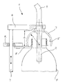
- Im Nachstehenden wird ein Ausführungsbeispiel der Erfindung anhand der Zeichnung beschrieben. Diese zeigt einen senkrechten Schnitt durch eine Vorrichtung 1 zum Erwärmen von Kunststoff-Flaschen F.
- Die Vorrichtung 1 weist einen horizontalen Träger 6 auf, an dessen einem Ende eine senkrecht stehende, rohrförmige Düse 2 befestigt ist. Diese ist über eine flexible Gasleitung 4 und ein nicht gezeigtes Steuerventil mit einer Quelle für sterile Heißluft verbunden. Das andere Ende des Trägers 6 ist an einer senkrechten, höhenbeweglichen Stange 7 befestigt, die durch einen nicht gezeigten Hubantrieb auf- und abbewegt werden kann.
- Am oberen Ende der Düse 2 dicht unterhalb des Trägers 6 ist eine rotationssymmetrische Glocke 3 konzentrisch zur Düse 2 befestigt oder einstückig mit dieser ausgebildet. Die Innenseite 5 der Glocke 3 hat die Form einer Kalotte mit dem Radius r. Die Schnittebene der Kalotte verläuft horizontal und definiert die untere Öffnung der Glocke 3. Am oberen Endbereich geht die Innenseite 5 der Glocke 3 abgerundet in die zylindrische Außenseite der Düse 2 über. Auch die Außenseite der Glocke 3 ist überwiegend kalottenförmig.
- Die vorbeschriebene Vorrichtung 1 ist zusammen mit einer Anzahl identischer Vorrichtungen auf dem Umfang eines Rotors R angeordnet, der um eine senkrechte Achse umläuft. An dem Rotor R ist für jede Vorrichtung 1 ein radial nach außen stehender Gefäßhalter 8 angeordnet, beispielsweise in Form einer gefederten Klammer, wie sie im deutschen Gebrauchsmuster 297 13 510 beschrieben ist. Durch den Gefäßhalter 8 wird eine Flasche F unterhalb ihres Tragrings ergriffen und vorübergehend konzentrisch zur zugehörigen Düse 2 fixiert. Während des Ein- und Ausführens einer Flasche F in einen Gefäßhalter 8 ist die Düse 2 mittels der Stange 7 entsprechend angehoben; nach dem Einsetzen einer zu behandelnden Flasche F in den Gefäßhalter 8 wird die Düse 2 zusammen mit ihrer Glocke 3 in die dargestellte untere End- und Arbeitsposition abgesenkt.
- In der Arbeitsposition liegt die Öffnung der Glocke 3 geringfügig tiefer als der Tragring der Flasche F und es besteht ein vorgegebener Abstand von wenigen mm zwischen der Flaschenöffnung und der Außenseite des mit einem Gewinde versehenen Flaschenkopfs.
- Wie die Zeichnung zeigt, ist die Höhe h der Kalotte geringfügig größer als ihr Radius r, so dass der untere, freie Rand der als Strömungs-Leitfläche dienenden Innenseite 5 leicht nach innen gewölbt ist. Hierdurch wird eine besonders gut Anströmung des Flaschenkopfs erzielt.
- Mit der vorbeschriebenen Vorrichtung 1 kann eine Flasche F in kurzer Zeit durch Einblasen von Heißluft gleichmäßig erwärmt werden und zwar sowohl im relativ dünnen Wandbereich als auch im relativ dicken bzw. doppelwandigen Kopfbereich, da die erfindungsgemäße kalottenförmige Gestaltung der Glocke 3 für eine effektive Erwärmung des Flaschenkopfs von außen her sorgt.
- Entsprechend vorteilhaft ist die Wirkung auch bei der Behandlung mit einem gasförmigen Sterilisationsmittel, z. B. einem Gemisch aus Luft und Wasserstoffperoxid, sowie bei anderen Düsenformen oder geringfügigen Abweichungen von der reinen Kalottenform, die zudem aufgrund ihrer "glatten" Gestalt die Reinigung begünstigt.
Claims (5)
- Vorrichtung (1) zum Behandeln von offenen Gefäßen, insbesondere Flaschen (F), mit einer in die Gefäßöffnung einfahrbaren, an mindestens eine Gasleitung (4) angeschlossenen Düse (2) und einer dieser zugeordneten, den Gefäßkopf mit Abstand umgebenden Glocke (3) zum Umlenken des aus der Gefäßöffnung austretenden Gases an den Gefäßkopf, dadurch gekennzeichnet, dass die als Leitfläche dienende Innenseite der Glocke (3) im Wesentlichen kalottenförmig ist.
- Vorrichtung nach Anspruch 1, dadurch gekennzeichnet, dass die kalottenförmige Innenseite (5) der Glocke (3) konzentrisch zu der rohrartigen Düse (2) angeordnet ist.
- Vorrichtung nach Anspruch 2, dadurch gekennzeichnet, dass die kalottenförmige Innenseite (5) der Glocke (3) abgerundet in die Außenseite der rohrartigen Düse (2) übergeht.
- Vorrichtung nach einem der Ansprüche 1 bis 3, dadurch gekennzeichnet, dass die Glocke (3) fest mit der Düse (2) verbunden ist.
- Vorrichtung nach einem der Ansprüche 1 bis 4, dadurch gekennzeichnet, dass die Höhe der Kalotte größer ist als ihr Radius, so dass der die Öffnung bildende freie Rand der Innenseite (5) nach innen gewölbt ist.
Applications Claiming Priority (1)
| Application Number | Priority Date | Filing Date | Title |
|---|---|---|---|
| DE202006019136U DE202006019136U1 (de) | 2006-12-18 | 2006-12-18 | Vorrichtung zum Behandeln von offenen Gefäßen |
Publications (1)
| Publication Number | Publication Date |
|---|---|
| EP1944263A1 true EP1944263A1 (de) | 2008-07-16 |
Family
ID=39079098
Family Applications (1)
| Application Number | Title | Priority Date | Filing Date |
|---|---|---|---|
| EP07019677A Withdrawn EP1944263A1 (de) | 2006-12-18 | 2007-10-09 | Vorrichtung zum Behandeln von offenen Gefässen |
Country Status (2)
| Country | Link |
|---|---|
| EP (1) | EP1944263A1 (de) |
| DE (1) | DE202006019136U1 (de) |
Cited By (2)
| Publication number | Priority date | Publication date | Assignee | Title |
|---|---|---|---|---|
| EP2448831A4 (de) * | 2009-07-03 | 2012-11-21 | Tetra Laval Holdings & Finance | Vorrichtung und verfahren zur gasflussbehandlung von paketen |
| EP2857046B1 (de) * | 2013-10-07 | 2019-06-12 | Mitsubishi Heavy Industries Machinery Systems, Ltd. | Sterilisierungsvorrichtung und sterilisierungsmethode |
Families Citing this family (3)
| Publication number | Priority date | Publication date | Assignee | Title |
|---|---|---|---|---|
| EP2261169A1 (de) * | 2009-06-12 | 2010-12-15 | INDAG Gesellschaft für Industriebedarf mbH & Co. Betriebs KG | Verfahren und Vorrichtung zum Desinfizieren von Getränkeverpackungen bei der Befüllung mit Produkt und Vorrichtung zum Aufbringen und/oder Sprühen von Desinfektionsmittel auf Getränkeverpackungen |
| DE102011075237A1 (de) | 2011-05-04 | 2012-11-08 | Krones Aktiengesellschaft | Behälterbehandlungsmaschine |
| DE102012107768B4 (de) * | 2012-08-23 | 2023-04-27 | Krones Ag | Vorrichtung und Verfahren zum Sterilisieren von Behältern |
Citations (2)
| Publication number | Priority date | Publication date | Assignee | Title |
|---|---|---|---|---|
| DE20300522U1 (de) * | 2003-01-14 | 2004-05-27 | Salda, Luciano, Vignola | Sterilisiervorrichtung |
| WO2006053745A1 (de) * | 2004-11-18 | 2006-05-26 | Sig Technology Ag | Verfahren und vorrichtung zum sterilisieren kontinuierlich bewegter kunststoffflaschen |
Family Cites Families (5)
| Publication number | Priority date | Publication date | Assignee | Title |
|---|---|---|---|---|
| FR688496A (fr) * | 1929-01-25 | 1930-08-23 | Seitz Werke Gmbh | Procédé et dispositif pour le remplissage et la fermeture aseptiques de récipients |
| FR971783A (fr) * | 1948-08-06 | 1951-01-22 | Dispositif de siphonage applicable, par exemple, au lait | |
| GB2030972B (en) * | 1978-08-12 | 1983-01-19 | Yoshino Kogyosho Co Ltd | Filling a bottle with a high temperature liquid |
| FR2599711B1 (fr) * | 1986-06-05 | 1988-09-23 | Erca Holding | Dispositif de dosage et de distribution pour le conditionnement de produits liquides |
| DE19719911A1 (de) * | 1997-05-13 | 1998-11-19 | Max Kettner Gmbh & Co Kg I K | Vorrichtung zur Behandlung von Getränkebehältern |
-
2006
- 2006-12-18 DE DE202006019136U patent/DE202006019136U1/de not_active Expired - Lifetime
-
2007
- 2007-10-09 EP EP07019677A patent/EP1944263A1/de not_active Withdrawn
Patent Citations (2)
| Publication number | Priority date | Publication date | Assignee | Title |
|---|---|---|---|---|
| DE20300522U1 (de) * | 2003-01-14 | 2004-05-27 | Salda, Luciano, Vignola | Sterilisiervorrichtung |
| WO2006053745A1 (de) * | 2004-11-18 | 2006-05-26 | Sig Technology Ag | Verfahren und vorrichtung zum sterilisieren kontinuierlich bewegter kunststoffflaschen |
Cited By (2)
| Publication number | Priority date | Publication date | Assignee | Title |
|---|---|---|---|---|
| EP2448831A4 (de) * | 2009-07-03 | 2012-11-21 | Tetra Laval Holdings & Finance | Vorrichtung und verfahren zur gasflussbehandlung von paketen |
| EP2857046B1 (de) * | 2013-10-07 | 2019-06-12 | Mitsubishi Heavy Industries Machinery Systems, Ltd. | Sterilisierungsvorrichtung und sterilisierungsmethode |
Also Published As
| Publication number | Publication date |
|---|---|
| DE202006019136U1 (de) | 2008-02-14 |
Similar Documents
| Publication | Publication Date | Title |
|---|---|---|
| DE2851013C2 (de) | Entkeimungsvorrichtung für strömendes Medium | |
| EP2640660B1 (de) | Füllelement sowie füllsystem oder füllmaschine zum freistrahlfüllen von flaschen oder dergleichen behältern | |
| WO2009047171A1 (de) | Vorrichtung zum sterilisieren von behältnissen | |
| EP2414272A2 (de) | Verfahren zum füllen von flaschen oder dergleichen behältern sowie füllmaschine | |
| DE202014103247U1 (de) | Nadelloses Anschlussmodul | |
| DE19958290B4 (de) | Zylindrischer Großbehälter mit einer Vorrichtung zum Reinigen und/oder Desinfizieren | |
| EP2049402A1 (de) | Vorrichtung und verfahren zur sterilisation von behältern | |
| DE202006019136U1 (de) | Vorrichtung zum Behandeln von offenen Gefäßen | |
| DE4219082A1 (de) | Verfahren und Vorrichtung zum aufeinanderfolgenden Füllen mehrerer Gefäße unter Atmosphärendruck | |
| DE2739742B2 (de) | Gefäßfüllvorrichtung | |
| DE2219665A1 (de) | Wasserregler | |
| DE102009031103A1 (de) | Verfahren und Vorrichtung zum Entgasen einer Flüssigkeit | |
| DE102016104286A1 (de) | Austrittsöffnung als Ringspalt ausgebildet und Spülgas = CO2 | |
| DE1566544C3 (de) | Verfahren und Vorrichtung zur Ver arbeitung von Ampullen und dabei ver wendbare Leerampulle | |
| DE2638749C3 (de) | Vorrichtung zum Füllen von Flaschen bei gleichbleibendem Druck | |
| WO2012022531A2 (de) | Verfahren und vorrichtung zur entnahme einer probe aus einem dampferzeuger | |
| DE2214435B2 (de) | Naßabscheider für slaubhaltige Gase oder Luft | |
| DE102005014076A1 (de) | Verfahren und Vorrichtung zum Spülen von Gefässen, insbesondere von Flaschen, mit einem gasförmigen Medium | |
| DE2428613C3 (de) | Vorrichtung zum Desinfizieren der Luftschächte von Klimaanlagen | |
| EP3044304B1 (de) | Behälter mit flexibler wandung | |
| DE19720987C2 (de) | Ausdehnungsgefäß mit Membrane | |
| DE102022124793A1 (de) | Füllmaschine zum Befüllen von Behältern mit einem flüssigen Füllgut | |
| DE199972C (de) | ||
| DE2804379C3 (de) | Behälterfüllorgan mit Scherbendusche | |
| AT214302B (de) | Verfahren und Vorrichtung zum sterilen Abfüllen von heißen kohlensäurehaltigen Trinkflüssigkeiten, insbesondere Bier |
Legal Events
| Date | Code | Title | Description |
|---|---|---|---|
| PUAI | Public reference made under article 153(3) epc to a published international application that has entered the european phase |
Free format text: ORIGINAL CODE: 0009012 |
|
| AK | Designated contracting states |
Kind code of ref document: A1 Designated state(s): AT BE BG CH CY CZ DE DK EE ES FI FR GB GR HU IE IS IT LI LT LU LV MC MT NL PL PT RO SE SI SK TR |
|
| AX | Request for extension of the european patent |
Extension state: AL BA HR MK RS |
|
| 17P | Request for examination filed |
Effective date: 20080708 |
|
| 17Q | First examination report despatched |
Effective date: 20080905 |
|
| AKX | Designation fees paid |
Designated state(s): DE FR GB IT SI |
|
| STAA | Information on the status of an ep patent application or granted ep patent |
Free format text: STATUS: THE APPLICATION IS DEEMED TO BE WITHDRAWN |
|
| 18D | Application deemed to be withdrawn |
Effective date: 20090317 |