EP1943032B1 - Dispositif pour aligner des cylindres de travail sur une ligne de laminoir - Google Patents
Dispositif pour aligner des cylindres de travail sur une ligne de laminoir Download PDFInfo
- Publication number
- EP1943032B1 EP1943032B1 EP05792837A EP05792837A EP1943032B1 EP 1943032 B1 EP1943032 B1 EP 1943032B1 EP 05792837 A EP05792837 A EP 05792837A EP 05792837 A EP05792837 A EP 05792837A EP 1943032 B1 EP1943032 B1 EP 1943032B1
- Authority
- EP
- European Patent Office
- Prior art keywords
- toggle
- lever
- wedge
- supported
- joint
- Prior art date
- Legal status (The legal status is an assumption and is not a legal conclusion. Google has not performed a legal analysis and makes no representation as to the accuracy of the status listed.)
- Not-in-force
Links
- 238000005096 rolling process Methods 0.000 title claims abstract description 35
- 238000006073 displacement reaction Methods 0.000 claims abstract description 6
- 230000002706 hydrostatic effect Effects 0.000 description 3
- 238000003860 storage Methods 0.000 description 3
- 238000000034 method Methods 0.000 description 2
- 230000006978 adaptation Effects 0.000 description 1
- 238000005452 bending Methods 0.000 description 1
- 238000005097 cold rolling Methods 0.000 description 1
- 238000010276 construction Methods 0.000 description 1
- 238000004519 manufacturing process Methods 0.000 description 1
- 125000006850 spacer group Chemical group 0.000 description 1
Images

Classifications
-
- B—PERFORMING OPERATIONS; TRANSPORTING
- B21—MECHANICAL METAL-WORKING WITHOUT ESSENTIALLY REMOVING MATERIAL; PUNCHING METAL
- B21B—ROLLING OF METAL
- B21B31/00—Rolling stand structures; Mounting, adjusting, or interchanging rolls, roll mountings, or stand frames
- B21B31/16—Adjusting or positioning rolls
- B21B31/20—Adjusting or positioning rolls by moving rolls perpendicularly to roll axis
- B21B31/22—Adjusting or positioning rolls by moving rolls perpendicularly to roll axis mechanically, e.g. by thrust blocks, inserts for removal
- B21B31/28—Adjusting or positioning rolls by moving rolls perpendicularly to roll axis mechanically, e.g. by thrust blocks, inserts for removal by toggle-lever mechanisms
-
- B—PERFORMING OPERATIONS; TRANSPORTING
- B21—MECHANICAL METAL-WORKING WITHOUT ESSENTIALLY REMOVING MATERIAL; PUNCHING METAL
- B21B—ROLLING OF METAL
- B21B31/00—Rolling stand structures; Mounting, adjusting, or interchanging rolls, roll mountings, or stand frames
- B21B31/16—Adjusting or positioning rolls
- B21B31/20—Adjusting or positioning rolls by moving rolls perpendicularly to roll axis
- B21B31/22—Adjusting or positioning rolls by moving rolls perpendicularly to roll axis mechanically, e.g. by thrust blocks, inserts for removal
- B21B31/30—Adjusting or positioning rolls by moving rolls perpendicularly to roll axis mechanically, e.g. by thrust blocks, inserts for removal by wedges or their equivalent
-
- B—PERFORMING OPERATIONS; TRANSPORTING
- B21—MECHANICAL METAL-WORKING WITHOUT ESSENTIALLY REMOVING MATERIAL; PUNCHING METAL
- B21B—ROLLING OF METAL
- B21B13/00—Metal-rolling stands, i.e. an assembly composed of a stand frame, rolls, and accessories
- B21B13/02—Metal-rolling stands, i.e. an assembly composed of a stand frame, rolls, and accessories with axes of rolls arranged horizontally
- B21B2013/025—Quarto, four-high stands
Definitions
- the invention relates to a device for aligning work rolls on the rolling line, in particular in quarto scaffolding, by means of at least one acting on roll chocks wedge pair in the area between parallel spaced rolling stand, which are arranged displaceable relative to the uprights by means of a toggle lever position on a horizontal slideway.
- a lower work roll in a rolling mill to the rolling line Hilfsanmaschineen in various designs are known, for example, as wedge adjustment, Spindelhubgetriebe, step wedges, manual Plattenbeilage, hydraulic cylinders, spindle adjustment and designs by means of toggle.
- Cylinder-actuated auxiliary settings can be moved quickly, but can only be used for small angles because of the required self-locking. By contrast, spindle-movable wedge adjustments are relatively slow.
- the document EP 0 513 946 B1 discloses a device for matching the upper edge of the lower work roll of rolling stands, in particular Quarto stands to the rolling line, by means of a pair of wedges below each lower roll chock, consisting of a lower horizontally displaceable in Walzenachsplatz wedge element and an upper, exclusively displaceable in the vertical direction wedge element, the during the rolling process with their wedge surfaces lie on each other.
- Each upper wedge element can be raised and lowered by means of a lifting device together with the respective roll chock.
- the wedge surfaces of both wedges are stepped like a step, the steps interlocking supporting the wedge elements vertically.
- the document EP 0 231 445 B1 discloses a method for height displacement of rolls in rolling mills, for matching the upper edge of the lower work roll to the rolling line and for changing the rolls, especially in quarto stands, equipped with a roll changing carriage, which is movable in the longitudinal direction of the rolls and replaceable step plates variable thickness or Height for grading the chocks of the support rollers has, as well as vertical lifting elements for temporarily supporting the chocks.
- the height displacement is carried out in such a way that with several step plates of different height, starting with the lowest level, this is in each case continuously raised by means of a lifting element with a short vertical stroke until the lower level has reached the level of the next higher level, in which case the vertical lifting elements take over the support of the chocks in the meantime until the lifting element with a short vertical stroke moved back to its lower position and the next higher step plate was driven under the chocks.
- the document DE-OS 25 13 666 describes a rolling stand with spindle actuated wedge adjustment for adjusting and / or readjusting the recess height by pressure cylinder for canceling the weight of the lower set of rollers when operating the wedge adjustment.
- two pressure medium cylinders are provided in each roll stand of the rolling stand.
- the document DE 28 06 525 C2 describes a device for extending the rolls of rolling stands, in particular of four-roll rolling stands, and for matching the upper edge of the lower work rolls to the rolling line, by means of an extension slide.
- On the extension slide more fitting sections of different thickness are arranged and retractable by means of a sliding drive under the chocks.
- Lifting devices are provided for supporting the chocks.
- the fitting portions are arranged in a movable on a path located on the Ausfahrschlitten path and connected to the displacement drive shifting frame and the lifting devices are arranged on both sides of the sliding frame in the Ausfahrschlitten.
- the document US 4,237,715 discloses a mechanism for vertically adjusting the lower backup roll of a four-high stand to the pass line. There are provided means for lifting the chocks, so that when lifting the same each stepwise spacer elements between the chocks and the roll stand can be inserted.
- the document JP-A-7 26 59 19 describes a device for adjusting the pass line by means of retractable step wedges between chocks of the lower support roller and rolling stand.
- the wedges which can be inserted for the purpose of changing the distance have stepped support surfaces and a smooth counter surface. In order to avoid unwanted deviations, the wedges are inserted with the smooth surface upwards and with the gradations downwards.
- the document DE-OS 2 241 833 discloses a roll stopper for setting rolls of different widths in the same stand.
- the Anstellorgane provided with bearing surfaces for rollers with different storage distances of the chocks.
- the Anstellorgane may have at their pressure pieces of the rollers facing side in the direction of the roller center line and parallel to the same extending flat surfaces and on the opposite sides wedge-shaped inclined surfaces which rest on the inclined surfaces of slidable in the direction of the roller center line wedges.
- the sliding wedges have on the, the wedge-shaped inclined surfaces opposite sides on flat surfaces which run parallel to the roller center line and slide on flat arranged in the roll stand surfaces.
- the document DE-OS 37 37 807 A1 discloses an invention which relates to a rolling mill, in particular cold rolling mill, with at least two in particular four to ten mainly superposed rollers, wherein directly on the outer shell of the roll bales a hydraulic medium via at least one expedient at least two hydrostatic bearing elements and acting on hydrostatic bearing elements Hydraulic cylinder acts or act.
- a wedge adjustment with parallel to the roll axes relative to each other sliding wedge surfaces below at least two hydrostatic acting on roll bales bearing elements of the lower roller, among other things, to compensate for wear of the lower set of rolls or the lowest roller.
- the actuator or pressure medium supply for the purpose of controlling the elastic bending line of the lower roller is actuated by signal generator.
- the computer compares the target values entered for the material to be processed with the actual values of the signal generator, which are arranged in a flatness measuring device, wherein also a control of directly on the roller bearings or acting on the roller bearing journals of support rollers lifting hydraulic cylinders are combined with it.
- the document DE-OS 37 37 100 A1 discloses a control on rolling mills. Rolling mills and calenders are operated by hydraulic cylinders to produce the rolling force. Rolling mills can be up to 8000 tonnes in quarto sheet rolling mills. It proposes the use of a mechanical roll gap change with the highest rolling force by means of a toggle and roller spindle and roll-supported elements. This should considerably reduce the required control forces, make the adjustment more sensitive and should also enable adjustments in the ⁇ range.
- the present invention seeks to develop a mechanically fast and easy-working device for high forces for variable pass line employment in rolling stands.
- the invention is based on the operation, the Anstell wedges on a toggle to move quickly in the rolling position or to pull out the wedges quickly to change the roll.
- the toggle lever joint is connected to the piston rod of a force means which is supported by a joint and either an angular position or a stretched position of the toggle lever is set by retracting or retracting the piston rod.
- a preferred embodiment of the device provides that the toggle joint is arranged longitudinally adjustable by means of a threaded spindle on one of the levers.
- Kniehebeigelenk is arranged longitudinally adjustable on the supported on the wedge lever by means of a threaded spindle with attached drive motor.
- the toggle joint comprises a to the axis (x-x) of the lever transversely arranged strut, at the end of each of the lever and the piston rod of the power means are mounted.
- each wedge has an oblique sliding surface on its upper side.
- Another embodiment provides that the drive motor is connected via a worm gear with the strut.
- the piston rod on the cylinder of the power means has a hydraulic device for its extension.
- the cylinder of the power means is pivotally mounted about a horizontal axis.
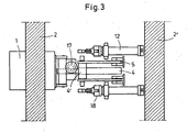
- the three figures show, respectively, a device for matching the upper edge of a lower work roll to the rolling line, in particular of quarto stands, by means of a pair of wedges 1,1 'below their lower roll chocks, comprising a pair of fixedly spaced wedges 1, 1 'between parallel spaced roll stand 2, 2', which are arranged in the form of a toggle auxiliary position 13, 14 relative to the uprights displaceable on a horizontal slide 3, wherein for the auxiliary position an arrangement of two toggle lever 4, 5 is provided of which the one lever 4 with horizontal joints 6 on the inside of the first wedge 1 via a threaded spindle 8 with attached drive motor 9 is supported longitudinally adjustable, and the other lever 5 produces a hinge connection between the other stand 2 'and the toggle joint 7, wherein He is about a horizontal hinge 10 on the inside of the second Stands 1 'is supported, and the toggle joint 7 in turn connected to the piston rod 11 of a force means 12 either in an angular position 13 or in a stretched position 14, wherein it oscillates
- the drive motor 9 is connected via a worm gear 17 with the strut 4 '.
- the piston rod 11 in the cylinder, the power means 12 is equipped with a hydraulic device 18 for the extension thereof.
- the cylinder of the power means 12 is pivotally mounted about a horizontal axis 15.
- the driving of the rolling stand takes only a few seconds.
- Previous auxiliary positions could be opened by 20 mm per second, this now reaches the same target with up to 40 mm per second.
- the adjustment to the exact rolling position for a constant fitting line with different roller diameters is effected by means of a spindle, which is designed as a lever arm of the toggle lever.
- a spindle By rotating the spindle over e.g. a gear motor, an effective lever length of the toggle construction is changed so that the retracted wedge is positionable in its vertical position. Under rolling force, the wedges are firmly positioned as they support themselves over the extended toggle on the stand spar.
- the device can be arranged in the upper and in the lower roll stand crosshead. Another advantage results from the fact that all components are easy to process production parts.
Landscapes
- Engineering & Computer Science (AREA)
- Mechanical Engineering (AREA)
- Metal Rolling (AREA)
- Reduction Rolling/Reduction Stand/Operation Of Reduction Machine (AREA)
- Bending Of Plates, Rods, And Pipes (AREA)
- Harvester Elements (AREA)
- Lifting Devices For Agricultural Implements (AREA)
Claims (10)
- Dispositif pour aligner des cylindres de travail sur la ligne de laminage, en particulier dans le cas de cages quarto, au moyen d'au moins une paire de cales agissant sur les empoises de cylindre, avec des cales (1, 1') dans la zone entre des montants (2, 2') de cage de laminage écartés parallèlement, qui sont disposées de manière mobile par rapport aux montants (2, 2') au moyen d'un réglage à grenouillère sur une surface de guidage horizontale, caractérisé en ce que les cales (1, 1') de la paire de cales sont reliées l'une à l'autre à distance fixe, en ce que pour leur déplacement, une disposition de deux grenouillères (4, 5) est prévue, dont un levier (4) s'appuie avec au moins une articulation (6) sur une cale (1) et l'autre levier (5) s'appuie avec au moins une articulation (10) sur le montant opposé (2') et les deux leviers (4, 5) sont reliés l'un à l'autre via une articulation à grenouillère (7) ajustable en longueur.
- Dispositif selon la revendication 1, caractérisé en ce que l'articulation à grenouillère (7) est reliée à la tige (11) de piston d'un moyen d'entraînement (12), qui est supporté par une articulation (15) et soit une position angulaire (13) soit une position étendue (14) des grenouillères (5, 6) est réglée par la sortie ou la rentrée de la tige (11) du piston.
- Dispositif selon la revendication 1 ou 2, caractérisé en ce que l'articulation à grenouillère (7) est disposée de manière réglable en longueur au moyen d'une vis filetée (8) sur un des leviers (4, 5).
- Dispositif selon la revendication 3, caractérisé en ce que l'articulation à grenouillère (7) est disposée de manière réglable en longueur sur le levier (4) appuyé sur la cale (1) au moyen d'une vis filetée avec un moteur d'entraînement (9) accolé.
- Dispositif selon l'une ou plusieurs des revendications 1 à 4, caractérisé en ce que l'articulation à grenouillère (7) comprend une bielle (4') disposée transversalement par rapport à l'axe (x-x) du levier (4), à l'extrémité de laquelle sont à chaque fois logés le levier (5) et la tige (11) du piston du moyen d'entraînement (12).
- Dispositif selon l'une ou plusieurs des revendications 1 à 5, caractérisé en ce que chaque cale (1, 1') présente une surface de guidage (16, 16') inclinée en sa surface supérieure.
- Dispositif selon l'une ou plusieurs des revendications 1 à 6, caractérisé en ce que le moteur d'entraînement (9) est relié à la bielle (4') au moyen d'un dispositif d'entraînement à vis (17).
- Dispositif selon l'une ou plusieurs des revendications 1 à 7, caractérisé en ce que la tige (11) de piston présente, dans le cylindre du moyen d'entraînement (12) un dispositif hydraulique (18) destiné à son allongement.
- Dispositif selon l'une ou plusieurs des revendications 1 à 8, caractérisé en ce que le cylindre du moyen d'entraînement (12) est disposé de manière à pouvoir pivoter autour d'un axe (15).
- Dispositif selon l'une ou plusieurs des revendications 1 à 9, caractérisé en ce que toutes les articulations du dispositif présentent des axes de pivotement horizontaux.
Applications Claiming Priority (1)
| Application Number | Priority Date | Filing Date | Title |
|---|---|---|---|
| PCT/EP2005/010962 WO2007042060A1 (fr) | 2005-10-12 | 2005-10-12 | Dispositif pour aligner des cylindres de travail sur une ligne de laminoir |
Publications (2)
| Publication Number | Publication Date |
|---|---|
| EP1943032A1 EP1943032A1 (fr) | 2008-07-16 |
| EP1943032B1 true EP1943032B1 (fr) | 2009-03-11 |
Family
ID=35453543
Family Applications (1)
| Application Number | Title | Priority Date | Filing Date |
|---|---|---|---|
| EP05792837A Not-in-force EP1943032B1 (fr) | 2005-10-12 | 2005-10-12 | Dispositif pour aligner des cylindres de travail sur une ligne de laminoir |
Country Status (8)
| Country | Link |
|---|---|
| US (1) | US7784321B2 (fr) |
| EP (1) | EP1943032B1 (fr) |
| JP (1) | JP2009511274A (fr) |
| CN (1) | CN101291752A (fr) |
| AT (1) | ATE424945T1 (fr) |
| CA (1) | CA2601775A1 (fr) |
| DE (1) | DE502005006852D1 (fr) |
| WO (1) | WO2007042060A1 (fr) |
Families Citing this family (2)
| Publication number | Priority date | Publication date | Assignee | Title |
|---|---|---|---|---|
| AT504209B1 (de) * | 2006-11-16 | 2008-04-15 | Voest Alpine Ind Anlagen | Walzenwechseleinrichtung mit keilverstelleinrichtung |
| GB2509266B (en) * | 2011-09-23 | 2018-04-11 | Shanghai Yinsheng Rubber & Plastic Company Ltd | Decorative material rolling machine having adjustable roll spacing |
Family Cites Families (20)
| Publication number | Priority date | Publication date | Assignee | Title |
|---|---|---|---|---|
| US679413A (en) * | 1900-09-18 | 1901-07-30 | Thomas Bunker | Rolling-mill. |
| US2635492A (en) * | 1946-03-20 | 1953-04-21 | Martin S Gettig | Plug-handling mechanism for seamless tube mills |
| JPS5311943B2 (fr) * | 1973-09-04 | 1978-04-25 | ||
| FR2258951B1 (fr) * | 1974-01-28 | 1977-03-04 | Jambon Anciens Ateliers | |
| US4038857A (en) * | 1976-04-26 | 1977-08-02 | Blaw-Knox Foundry & Mill Machinery, Inc. | Hydraulic mill stand |
| DE2758340A1 (de) * | 1977-12-27 | 1979-07-05 | Pfister Waagen Gmbh | Hydrostatische stellvorrichtung |
| US4237715A (en) * | 1979-04-05 | 1980-12-09 | Gulf & Western Manufacturing Company | Rolling mill pass-line adjusting mechanism |
| JPS6026612B2 (ja) * | 1982-02-10 | 1985-06-25 | 新日本製鐵株式会社 | 帯状材の成形ロ−ル圧下装置 |
| JPS5950905A (ja) * | 1982-09-17 | 1984-03-24 | Ube Ind Ltd | 鋼材圧延装置 |
| JPS59106603A (ja) * | 1982-12-07 | 1984-06-20 | 財団法人鉄道総合技術研究所 | 硬頭レールの現場接合方法 |
| JPS6089910A (ja) * | 1983-10-24 | 1985-05-20 | Toshiba Chem Corp | カバ−付きトランスのワニス処理方法 |
| JPS6163309A (ja) * | 1984-09-06 | 1986-04-01 | Sumitomo Metal Ind Ltd | プラグミル |
| DE3544781A1 (de) * | 1985-12-18 | 1987-06-19 | Schloemann Siemag Ag | Verfahren und vorrichtung zur hoehenverlagerung von walzen in walzgeruesten |
| US4842800A (en) | 1987-10-01 | 1989-06-27 | General Electric Company | Method of encapsulating electronic devices |
| DE8713454U1 (fr) * | 1987-10-07 | 1988-02-04 | Rollwalztechnik Abele + Hoeltich Gmbh, 7707 Engen, De | |
| US4939479A (en) * | 1989-08-31 | 1990-07-03 | Sgs-Thomson Microelectronics (Pte) Ltd. | Audio amplifier |
| DE4115958C2 (de) * | 1991-05-13 | 1994-04-07 | Mannesmann Ag | Vorrichtung zum Angleichen der Oberkante der unteren Arbeitswalze an die Walzlinie |
| JP2572544B2 (ja) * | 1994-03-30 | 1997-01-16 | 住友金属工業株式会社 | パスライン調整装置 |
| JPH10175006A (ja) * | 1996-12-13 | 1998-06-30 | Ishikawajima Harima Heavy Ind Co Ltd | 圧延機のロールクロス機構 |
| JP2002102911A (ja) * | 2000-09-25 | 2002-04-09 | Kobe Steel Ltd | 圧延機パスライン高さ調整装置 |
-
2005
- 2005-10-12 CN CNA2005800518344A patent/CN101291752A/zh active Pending
- 2005-10-12 CA CA002601775A patent/CA2601775A1/fr not_active Abandoned
- 2005-10-12 EP EP05792837A patent/EP1943032B1/fr not_active Not-in-force
- 2005-10-12 US US11/887,319 patent/US7784321B2/en not_active Expired - Fee Related
- 2005-10-12 JP JP2008534873A patent/JP2009511274A/ja active Pending
- 2005-10-12 DE DE502005006852T patent/DE502005006852D1/de active Active
- 2005-10-12 WO PCT/EP2005/010962 patent/WO2007042060A1/fr active Application Filing
- 2005-10-12 AT AT05792837T patent/ATE424945T1/de active
Also Published As
| Publication number | Publication date |
|---|---|
| US7784321B2 (en) | 2010-08-31 |
| WO2007042060A1 (fr) | 2007-04-19 |
| JP2009511274A (ja) | 2009-03-19 |
| CA2601775A1 (fr) | 2007-04-19 |
| EP1943032A1 (fr) | 2008-07-16 |
| US20090064750A1 (en) | 2009-03-12 |
| DE502005006852D1 (de) | 2009-04-23 |
| CN101291752A (zh) | 2008-10-22 |
| ATE424945T1 (de) | 2009-03-15 |
Similar Documents
| Publication | Publication Date | Title |
|---|---|---|
| AT504640B1 (de) | Biegemaschine | |
| AT504209B1 (de) | Walzenwechseleinrichtung mit keilverstelleinrichtung | |
| DE3212070C2 (de) | Walzgerüst mit einer Vorrichtung zur Einhaltung der Ebenheit des gewalzten Guts | |
| EP2307152B1 (fr) | Dispositif de laminage | |
| EP2342026B1 (fr) | Dispositif de laminage | |
| EP0287848B1 (fr) | Cisaille à couper les bandes longitudinales | |
| EP3160726B1 (fr) | Presse à châssis en c, améliorée | |
| AT507110B1 (de) | Presse zum umformen von material | |
| EP1943032B1 (fr) | Dispositif pour aligner des cylindres de travail sur une ligne de laminoir | |
| DE10000349A1 (de) | Schrägwalzen-Richtmaschine | |
| DE102004049501A1 (de) | Vorrichtung zum Angleichen von Arbeitswalzen an die Walzlinie | |
| DE1961110A1 (de) | Walzwerk mit einem mehrteiligen Walzenstaender | |
| EP2424686B1 (fr) | Cage réversible à dispositifs de guidage d'entrée et de sortie | |
| EP3544750B1 (fr) | Cage refouleuse avec un dispositif de réglage rapide de cylindres de réglage | |
| DE2224875B2 (de) | Vorrichtung zum Belasten und Trennen der Walzen eines der Bearbeitung von Bahnen, insbesondere von Papierbahnen, dienenden Walzensatzes | |
| DE102018108733B4 (de) | Antriebsvorrichtung für eine Presse oder Stanze und Presse oder Stanze | |
| EP0484781B1 (fr) | Presse à refouler de brames pour laminoirs à chaud à larges bandes | |
| EP1650015A1 (fr) | Presse, presse de poinçonnage ou dispositif de formage | |
| DE4220043A1 (de) | Schneid- und Umformpresse mit einem oder mehreren Antriebzylindern und einem Gelenkhebelantrieb | |
| DE2334442B2 (de) | Anstellvorrichtung für Walzwerke mit geschlossenen Ständern | |
| DE1936769A1 (de) | Vorrichtung zur Balligkeitssteuerung der Arbeitswalzen in einem Duo-Metallwalzwerk | |
| DE2459784A1 (de) | Kaliberwalzgeruest, insbesondere fuer kontinuierliche feinstahlstrassen | |
| EP3536413A1 (fr) | Cage de laminoir pour un laminoir à chaud | |
| DE3208851A1 (de) | Dreiwalzen-biegepresse zum biegen von blechen und dergleichen | |
| DE4035001A1 (de) | Stauchpresse zur reduktion der breite von brammen in warmbreitband-vorstrassen |
Legal Events
| Date | Code | Title | Description |
|---|---|---|---|
| PUAI | Public reference made under article 153(3) epc to a published international application that has entered the european phase |
Free format text: ORIGINAL CODE: 0009012 |
|
| 17P | Request for examination filed |
Effective date: 20060803 |
|
| AK | Designated contracting states |
Kind code of ref document: A1 Designated state(s): AT BE BG CH CY CZ DE DK EE ES FI FR GB GR HU IE IS IT LI LT LU LV MC NL PL PT RO SE SI SK TR |
|
| GRAP | Despatch of communication of intention to grant a patent |
Free format text: ORIGINAL CODE: EPIDOSNIGR1 |
|
| GRAS | Grant fee paid |
Free format text: ORIGINAL CODE: EPIDOSNIGR3 |
|
| GRAA | (expected) grant |
Free format text: ORIGINAL CODE: 0009210 |
|
| AK | Designated contracting states |
Kind code of ref document: B1 Designated state(s): AT BE BG CH CY CZ DE DK EE ES FI FR GB GR HU IE IS IT LI LT LU LV MC NL PL PT RO SE SI SK TR |
|
| REG | Reference to a national code |
Ref country code: GB Ref legal event code: FG4D Free format text: NOT ENGLISH |
|
| REG | Reference to a national code |
Ref country code: CH Ref legal event code: EP |
|
| REG | Reference to a national code |
Ref country code: IE Ref legal event code: FG4D Free format text: LANGUAGE OF EP DOCUMENT: GERMAN |
|
| REF | Corresponds to: |
Ref document number: 502005006852 Country of ref document: DE Date of ref document: 20090423 Kind code of ref document: P |
|
| RAP2 | Party data changed (patent owner data changed or rights of a patent transferred) |
Owner name: SMS SIEMAG AG |
|
| PG25 | Lapsed in a contracting state [announced via postgrant information from national office to epo] |
Ref country code: SI Free format text: LAPSE BECAUSE OF FAILURE TO SUBMIT A TRANSLATION OF THE DESCRIPTION OR TO PAY THE FEE WITHIN THE PRESCRIBED TIME-LIMIT Effective date: 20090311 Ref country code: LT Free format text: LAPSE BECAUSE OF FAILURE TO SUBMIT A TRANSLATION OF THE DESCRIPTION OR TO PAY THE FEE WITHIN THE PRESCRIBED TIME-LIMIT Effective date: 20090311 Ref country code: NL Free format text: LAPSE BECAUSE OF FAILURE TO SUBMIT A TRANSLATION OF THE DESCRIPTION OR TO PAY THE FEE WITHIN THE PRESCRIBED TIME-LIMIT Effective date: 20090311 Ref country code: FI Free format text: LAPSE BECAUSE OF FAILURE TO SUBMIT A TRANSLATION OF THE DESCRIPTION OR TO PAY THE FEE WITHIN THE PRESCRIBED TIME-LIMIT Effective date: 20090311 |
|
| NLT2 | Nl: modifications (of names), taken from the european patent patent bulletin |
Owner name: SMS SIEMAG AG Effective date: 20090617 |
|
| NLV1 | Nl: lapsed or annulled due to failure to fulfill the requirements of art. 29p and 29m of the patents act | ||
| PG25 | Lapsed in a contracting state [announced via postgrant information from national office to epo] |
Ref country code: LV Free format text: LAPSE BECAUSE OF FAILURE TO SUBMIT A TRANSLATION OF THE DESCRIPTION OR TO PAY THE FEE WITHIN THE PRESCRIBED TIME-LIMIT Effective date: 20090311 Ref country code: SE Free format text: LAPSE BECAUSE OF FAILURE TO SUBMIT A TRANSLATION OF THE DESCRIPTION OR TO PAY THE FEE WITHIN THE PRESCRIBED TIME-LIMIT Effective date: 20090611 Ref country code: PL Free format text: LAPSE BECAUSE OF FAILURE TO SUBMIT A TRANSLATION OF THE DESCRIPTION OR TO PAY THE FEE WITHIN THE PRESCRIBED TIME-LIMIT Effective date: 20090311 |
|
| REG | Reference to a national code |
Ref country code: IE Ref legal event code: FD4D |
|
| PG25 | Lapsed in a contracting state [announced via postgrant information from national office to epo] |
Ref country code: EE Free format text: LAPSE BECAUSE OF FAILURE TO SUBMIT A TRANSLATION OF THE DESCRIPTION OR TO PAY THE FEE WITHIN THE PRESCRIBED TIME-LIMIT Effective date: 20090311 Ref country code: IE Free format text: LAPSE BECAUSE OF FAILURE TO SUBMIT A TRANSLATION OF THE DESCRIPTION OR TO PAY THE FEE WITHIN THE PRESCRIBED TIME-LIMIT Effective date: 20090311 Ref country code: PT Free format text: LAPSE BECAUSE OF FAILURE TO SUBMIT A TRANSLATION OF THE DESCRIPTION OR TO PAY THE FEE WITHIN THE PRESCRIBED TIME-LIMIT Effective date: 20090824 Ref country code: ES Free format text: LAPSE BECAUSE OF FAILURE TO SUBMIT A TRANSLATION OF THE DESCRIPTION OR TO PAY THE FEE WITHIN THE PRESCRIBED TIME-LIMIT Effective date: 20090622 |
|
| PG25 | Lapsed in a contracting state [announced via postgrant information from national office to epo] |
Ref country code: IS Free format text: LAPSE BECAUSE OF FAILURE TO SUBMIT A TRANSLATION OF THE DESCRIPTION OR TO PAY THE FEE WITHIN THE PRESCRIBED TIME-LIMIT Effective date: 20090711 Ref country code: SK Free format text: LAPSE BECAUSE OF FAILURE TO SUBMIT A TRANSLATION OF THE DESCRIPTION OR TO PAY THE FEE WITHIN THE PRESCRIBED TIME-LIMIT Effective date: 20090311 Ref country code: RO Free format text: LAPSE BECAUSE OF FAILURE TO SUBMIT A TRANSLATION OF THE DESCRIPTION OR TO PAY THE FEE WITHIN THE PRESCRIBED TIME-LIMIT Effective date: 20090311 |
|
| PLBE | No opposition filed within time limit |
Free format text: ORIGINAL CODE: 0009261 |
|
| STAA | Information on the status of an ep patent application or granted ep patent |
Free format text: STATUS: NO OPPOSITION FILED WITHIN TIME LIMIT |
|
| PG25 | Lapsed in a contracting state [announced via postgrant information from national office to epo] |
Ref country code: DK Free format text: LAPSE BECAUSE OF FAILURE TO SUBMIT A TRANSLATION OF THE DESCRIPTION OR TO PAY THE FEE WITHIN THE PRESCRIBED TIME-LIMIT Effective date: 20090311 Ref country code: BG Free format text: LAPSE BECAUSE OF FAILURE TO SUBMIT A TRANSLATION OF THE DESCRIPTION OR TO PAY THE FEE WITHIN THE PRESCRIBED TIME-LIMIT Effective date: 20090611 |
|
| 26N | No opposition filed |
Effective date: 20091214 |
|
| BERE | Be: lapsed |
Owner name: SMS DEMAG A.G. Effective date: 20091031 |
|
| PG25 | Lapsed in a contracting state [announced via postgrant information from national office to epo] |
Ref country code: MC Free format text: LAPSE BECAUSE OF NON-PAYMENT OF DUE FEES Effective date: 20091031 |
|
| REG | Reference to a national code |
Ref country code: CH Ref legal event code: PL |
|
| PG25 | Lapsed in a contracting state [announced via postgrant information from national office to epo] |
Ref country code: GR Free format text: LAPSE BECAUSE OF FAILURE TO SUBMIT A TRANSLATION OF THE DESCRIPTION OR TO PAY THE FEE WITHIN THE PRESCRIBED TIME-LIMIT Effective date: 20090612 Ref country code: BE Free format text: LAPSE BECAUSE OF NON-PAYMENT OF DUE FEES Effective date: 20091031 Ref country code: CH Free format text: LAPSE BECAUSE OF NON-PAYMENT OF DUE FEES Effective date: 20091031 Ref country code: LI Free format text: LAPSE BECAUSE OF NON-PAYMENT OF DUE FEES Effective date: 20091031 |
|
| PGFP | Annual fee paid to national office [announced via postgrant information from national office to epo] |
Ref country code: CZ Payment date: 20101012 Year of fee payment: 6 |
|
| PG25 | Lapsed in a contracting state [announced via postgrant information from national office to epo] |
Ref country code: LU Free format text: LAPSE BECAUSE OF NON-PAYMENT OF DUE FEES Effective date: 20091012 |
|
| PG25 | Lapsed in a contracting state [announced via postgrant information from national office to epo] |
Ref country code: HU Free format text: LAPSE BECAUSE OF FAILURE TO SUBMIT A TRANSLATION OF THE DESCRIPTION OR TO PAY THE FEE WITHIN THE PRESCRIBED TIME-LIMIT Effective date: 20090912 |
|
| PGFP | Annual fee paid to national office [announced via postgrant information from national office to epo] |
Ref country code: FR Payment date: 20110503 Year of fee payment: 6 Ref country code: DE Payment date: 20110413 Year of fee payment: 6 Ref country code: GB Payment date: 20110323 Year of fee payment: 6 |
|
| PG25 | Lapsed in a contracting state [announced via postgrant information from national office to epo] |
Ref country code: TR Free format text: LAPSE BECAUSE OF FAILURE TO SUBMIT A TRANSLATION OF THE DESCRIPTION OR TO PAY THE FEE WITHIN THE PRESCRIBED TIME-LIMIT Effective date: 20090311 |
|
| PGFP | Annual fee paid to national office [announced via postgrant information from national office to epo] |
Ref country code: AT Payment date: 20110414 Year of fee payment: 6 |
|
| PG25 | Lapsed in a contracting state [announced via postgrant information from national office to epo] |
Ref country code: CY Free format text: LAPSE BECAUSE OF FAILURE TO SUBMIT A TRANSLATION OF THE DESCRIPTION OR TO PAY THE FEE WITHIN THE PRESCRIBED TIME-LIMIT Effective date: 20090311 |
|
| PGFP | Annual fee paid to national office [announced via postgrant information from national office to epo] |
Ref country code: IT Payment date: 20110331 Year of fee payment: 6 |
|
| GBPC | Gb: european patent ceased through non-payment of renewal fee |
Effective date: 20111012 |
|
| REG | Reference to a national code |
Ref country code: FR Ref legal event code: ST Effective date: 20120629 |
|
| PG25 | Lapsed in a contracting state [announced via postgrant information from national office to epo] |
Ref country code: CZ Free format text: LAPSE BECAUSE OF NON-PAYMENT OF DUE FEES Effective date: 20111012 Ref country code: DE Free format text: LAPSE BECAUSE OF NON-PAYMENT OF DUE FEES Effective date: 20120501 |
|
| REG | Reference to a national code |
Ref country code: DE Ref legal event code: R119 Ref document number: 502005006852 Country of ref document: DE Effective date: 20120501 |
|
| PG25 | Lapsed in a contracting state [announced via postgrant information from national office to epo] |
Ref country code: FR Free format text: LAPSE BECAUSE OF NON-PAYMENT OF DUE FEES Effective date: 20111102 Ref country code: GB Free format text: LAPSE BECAUSE OF NON-PAYMENT OF DUE FEES Effective date: 20111012 Ref country code: IT Free format text: LAPSE BECAUSE OF NON-PAYMENT OF DUE FEES Effective date: 20111012 |
|
| REG | Reference to a national code |
Ref country code: AT Ref legal event code: MM01 Ref document number: 424945 Country of ref document: AT Kind code of ref document: T Effective date: 20111012 |
|
| PG25 | Lapsed in a contracting state [announced via postgrant information from national office to epo] |
Ref country code: AT Free format text: LAPSE BECAUSE OF NON-PAYMENT OF DUE FEES Effective date: 20111012 |