EP1942787B1 - Procédé et appareil pour mesurer les caractéristiques de déformation d'un objet - Google Patents
Procédé et appareil pour mesurer les caractéristiques de déformation d'un objet Download PDFInfo
- Publication number
- EP1942787B1 EP1942787B1 EP06839630.8A EP06839630A EP1942787B1 EP 1942787 B1 EP1942787 B1 EP 1942787B1 EP 06839630 A EP06839630 A EP 06839630A EP 1942787 B1 EP1942787 B1 EP 1942787B1
- Authority
- EP
- European Patent Office
- Prior art keywords
- deformation
- target surface
- characteristic
- topographer
- interval
- Prior art date
- Legal status (The legal status is an assumption and is not a legal conclusion. Google has not performed a legal analysis and makes no representation as to the accuracy of the status listed.)
- Active
Links
Images


Classifications
-
- A—HUMAN NECESSITIES
- A61—MEDICAL OR VETERINARY SCIENCE; HYGIENE
- A61B—DIAGNOSIS; SURGERY; IDENTIFICATION
- A61B3/00—Apparatus for testing the eyes; Instruments for examining the eyes
- A61B3/10—Objective types, i.e. instruments for examining the eyes independent of the patients' perceptions or reactions
- A61B3/16—Objective types, i.e. instruments for examining the eyes independent of the patients' perceptions or reactions for measuring intraocular pressure, e.g. tonometers
- A61B3/165—Non-contacting tonometers
-
- A—HUMAN NECESSITIES
- A61—MEDICAL OR VETERINARY SCIENCE; HYGIENE
- A61B—DIAGNOSIS; SURGERY; IDENTIFICATION
- A61B3/00—Apparatus for testing the eyes; Instruments for examining the eyes
- A61B3/0008—Apparatus for testing the eyes; Instruments for examining the eyes provided with illuminating means
-
- A—HUMAN NECESSITIES
- A61—MEDICAL OR VETERINARY SCIENCE; HYGIENE
- A61B—DIAGNOSIS; SURGERY; IDENTIFICATION
- A61B3/00—Apparatus for testing the eyes; Instruments for examining the eyes
- A61B3/10—Objective types, i.e. instruments for examining the eyes independent of the patients' perceptions or reactions
- A61B3/107—Objective types, i.e. instruments for examining the eyes independent of the patients' perceptions or reactions for determining the shape or measuring the curvature of the cornea
Definitions
- Embodiments of the invention generally relate to methods and apparatus for measuring characteristics of a deformable object through changes in the surface of the object during a deformation interval. More particularly, embodiments of the invention relate to the measurement of physical and biomechanical characteristics of a live cornea.
- the measurement of the surface characteristics of an object can reveal much information about the physical and mechanical properties of the object. If the surface of the object is deformable in response to an applied force, measurement of the changes in characteristics of the surface may provide further useful information.
- a particularly interesting, exemplary object is the cornea of a human eye. The widespread interest in understanding the physical, biomechanical, optical and all other characteristics of the eye is obviously motivated. Over the years, different theories have been presented about the structural and dynamic properties of the eye, particularly the cornea. Earlier theories modeling the cornea as a solid structure have more recently given way to understanding the cornea as a layered, biodynamically responsive structure that to this day is not completely understood.
- topographical characteristics include corneal curvature and surface elevation with respect to a reference surface, as well as others known in the art.
- Corneal topography measuring devices are alternatively referred to as topographers, keratographers or keratometers (a topographer is a generic term referring to an apparatus for measuring the topographical characteristics of an object surface, while keratographer and keratometer more specifically refer to measurements of the cornea).
- topographers is a generic term referring to an apparatus for measuring the topographical characteristics of an object surface, while keratographer and keratometer more specifically refer to measurements of the cornea.
- Different devices use different measuring principles to determine various topographical characteristics of the cornea. For example, some devices use Placido-based reflective image analysis.
- Placido-based devices can measure curvature parameters of the cornea but typically lack the capability to directly measure surface elevation.
- the Orbscan ® anterior segment analyzer (Bausch & Lomb Incorporated) is a topography characteristic measuring device that utilizes a scanning optical slit. Device software provides for direct measurement of surface elevation and corneal thickness as well as surface curvature.
- Another commercial device developed by Par Technology Corporation is known as the PAR CTS TM Corneal Topography System (PAR).
- the PAR imaging system utilizes a raster photography method.
- the PAR CTS imaging system projects a known grid geometry onto the anterior corneal surface that is viewed by a camera from an offset axis.
- Other topography characteristic measuring techniques include confocal microscopy, optical coherence tomography, ultrasound, optical interferometry and others, all of which are well known in the art.
- topographical characteristics of the cornea provide a wealth of information about vision and the effects of corneal shape on visual performance
- corneal topography by itself cannot reveal the physical and biomechanical properties of the cornea necessary for a thorough understanding of its structure and function.
- One technique used to explore these properties is to deform the cornea with a known force and measure the response of the cornea to the force.
- An illustrative apparatus of this type is known in the art as a tonometer. Tonometers for measuring intraocular pressure (IOP) where originally developed as contact-type instruments, meaning that a portion of the instrument is brought into contact with the cornea during the measurement procedure.
- IOP intraocular pressure
- GAT Goldmann applanation tonometer
- Non-contact tonometers which operate by directing an air pulse generated by a pump mechanism through a discharge tube aimed at the cornea to cause applanation.
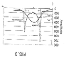
- an optoelectronic system monitors the cornea by detecting corneally reflected light from a beam obliquely incident upon the cornea.
- a peak detector signal occurs at the moment of applanation when the reflecting surface of the cornea is flat.
- the cornea is actually deformed from its original convex state through a first state of applanation to a slightly concave state and is allowed to return from concavity through a second state of applanation to convexity as the air pulse decays.
- a method for measuring IOP and a non-contact tonometer are disclosed in U.S. Patent Nos. 6,419,631 and 6,875,175 .
- This technology is commercially known as the Reichert (Depew, New York) Ocular Response Analyzer TM .
- the Reichert Ocular Response Analyzer utilizes a dynamic bidirectional applanation process to measure a cornea tissue property called corneal hysteresis.
- corneal hysteresis refers to the difference in pressure values of the air pulse at the inward moving applanation point and the outward moving applanation point during a measurement interval (inward moving refers to an initial convex corneal shape moving to a flattened condition, while the outward applanation point refers to the post air pulse concave corneal surface moving towards the applanation point on its return to a normal convex surface shape). Since corneal hysteresis appears to be a repeatable measurement, it may provide a metric that is useful for identifying and categorizing various conditions of the cornea.
- corneal hysteresis is alleged to aid in identifying and classifying conditions such as corneal ectasia and Fuch's Dystrophy, and as helping in the diagnosis and management of glaucoma. Differences in hysteresis measurements for different corneal conditions may better inform about the biomechanical and biodynamical properties of the cornea. Because corneal hysteresis measurement is credited for presenting a complete characterization of the cornea's biomechanical state, it is believed to have additional potential uses in screening refractive surgery candidates as well as predicting and controlling surgical outcomes. The interested reader is directed to the aforementioned website address for further information provided by the manufacturer. Document US 5033841 which is considered to represent the closest prior art to the subject-matter of apparatus claim 1 describes an integrated ophthalmological system which comprises a corneal topographer and a non-contact tonometer.
- the inventor has recognized that additional benefits could be obtained by a combination of the techniques and integration of the different apparatus.
- the inventor has further recognized the need for new and improved methods and apparatus that are capable of more efficiently measuring properties of the cornea, resulting in a better understanding of corneal biomechanics and biodynamics.
- Embodiments of the invention are generally directed to apparatus and methods for measuring a deformation characteristic of a deformable target surface. It is to be understood that the measurement principles of the invention may be applied to a large variety of organic (e.g., human, animal or plant tissue) and inorganic materials having a surface that can be deformed by an applied non-contact force. The surface may be light diffusing and non-transparent or non-diffusing and transparent. Apparatus suitable for measuring the surface topography characteristics of a deformable target surface during or over a deformation interval, that incorporate a component which can supply a non-contact force that deforms the target surface over the deformation interval, are considered to be within the scope of the claimed invention.
- organic e.g., human, animal or plant tissue
- inorganic materials having a surface that can be deformed by an applied non-contact force.
- the surface may be light diffusing and non-transparent or non-diffusing and transparent.
- an embodiment of the invention is directed to a device for measuring a deformation characteristic of a deformable target surface that includes a topographer and a non-contact target surface deformer that is operationally integrated with the topographer and is located along a first operational axis of the device.
- the topographer includes a high speed camera located along a second, operational axis of the device.
- a suitable camera or detector is required to capture sequential images or still images of specific deformation events during the deformation interval.
- the device also includes an optical system including a grid object and a light source for projecting a grid image, aligned along a third, operational axis of the device.
- at least one of the second and third axes are offset from the first axis. More particularly, all of the axes are directionally independent.
- the topographer advantageously is a computer-assisted videokeratography-based topographer (referred to herein as a corneal topographer).
- the corneal topographer is a modified PAR CTS imaging device.
- the non-contact target surface deformer is an air pressure pulse-based apparatus.
- the non-contact target surface deformer is a non-contact tonometer.
- the target surface to be measured is suitably positioned with respect to the device.
- the target surface subjected to the force and experiences responsive deformation over a deformation interval.
- a plurality of topography characteristic measurements are made during the deformation interval.
- Exemplary topography characteristic measurements may include, but are not limited to, surface curvature, surface elevation, surface indentation, surface deformation symmetry, surface deformation shape, surface deformation area, surface deformation hysteresis and elasticity, viscosity and pressure.
- An illustrative and particularly advantageous embodiment of the invention is directed to a device for measuring a deformation characteristic of a cornea.
- the device comprises a corneal topographer and a non-contact tonometer that is operationally integrated with the corneal topographer.
- the corneal topographer is a rasterstereography-based topographer. More particularly, the corneal topographer is a modified PAR CTS imaging device.
- a deformation characteristic of the cornea In addition to the measurable deformation characteristics listed above, dioptric power, intraocular pressure, corneal hysteresis, corneal elasticity, corneal viscosity and various known corneal topography characteristics can be measured.
- An embodiment of the invention is generally directed to a device for measuring a deformation characteristic of a deformable target surface.
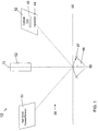
- An exemplary embodiment of the invention is directed to a device 10, as shown in Figure 1 , for measuring a deformation characteristic of a live cornea.
- the device 10 includes a corneal topographer 20 and a non-contact tonometer 30 that are operationally and physically integrated components of the device.
- the corneal topographer 20 of the device shown in Figure 1 is a rasterstereography-based topographer that is modeled after a PAR CTS corneal topography system. Such a system is disclosed in US Patent Nos. 4,995,716 and 5,159,361 , the disclosures of which are incorporated herein by reference to the fullest allowable extent as though fully set forth in their entireties.
- the corneal topographer 20 includes a high speed camera/detector 32 located along a second, operational axis 76 of the device 10 and an optical system 42, including a grid object 44 and a light source 45, for projecting a grid image, aligned along a third, operational axis 78 of the device 10.
- the target object in this case the cornea 87 of an eye 88, is located along a central device axis 82 in a measurement plane illustrated by dotted line 98.
- Various lenses and filters that are components of the PAR CTS corneal topographer 20 are not shown.
- the exemplary device 10 also includes a non-contact tonometer 52 located along a first operational axis 72.
- Axis 72 and axis 82 are coplanar.
- Second and third operational axes 76, 78 are thus off-set.
- non-contact tonometer 52 is a Reichert Ocular Response Analyzer, a description of which is set forth in aforementioned U.S. Patent Nos. 6,419,631 and 6,875,175 .
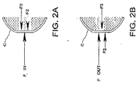
- the impulse energy imparted to the cornea by the air pulse reversibly deforms the cornea from its original state of convexity through a first state of applanation, P 1 , to a state of concavity.
- P 1 first state of applanation
- P 2 second state of applanation
- FIGS 2A and 2B are simplified diagrams showing the forces acting on a cornea C at the moment (t 1 ) of first applanation ( Figure 2A ) and second (t 2 ) applanation ( Figure 2B ) during the measurement interval, while ignoring dynamic effects.
- F 1 represents the inwardly directed force of an incident air pulse
- F 2 represents the force required to bend the corneal tissue itself
- F 3 represents the outwardly directed force attributed to intra-ocular pressure.
- the corneal topographer 20 can conveniently be triggered off of event P 1 at time t 1 , event P 2 at time t 2 ,, at peak plenum pressure and/or at any predetermined trigger points over the deformation interval T to obtain a plurality of deformation characteristic measurements.
- use of the PAR CTS system modified to incorporate a high speed camera/detector as the corneal topographer 20 in device 10 is advantageous because the off-set axes 76, 78 of the camera 32 and optical system 42 provide for a centralized location of the tonometer 52.
- a Placido-based topographer may not allow the tonometer to be centrally located, other topography characteristic measuring apparatus may provide a suitable physical arrangement to be used in device 10.
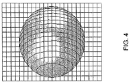
- Figures 4 and 5 show simulated PAR CTS grid images before and after, respectively, an air puff deformation of a corneal surface.
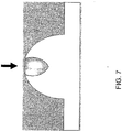
- Figure 6 illustrates a wide, shallow corneal indentation corresponding to that in Figure 5 .
- Figure 7 shows a narrower and deeper corneal indentation than that shown in Figure 6 .
- the figures illustrate that softer or stiffer corneas may respond differently to an applied deformation force.
- deformation characteristics can be measured with the device embodiment described above.
- the magnitude, the symmetry or asymmetry, the shape and the area of the surface deformation could be measured during the deformation interval, as well as applanation depth, corneal curvature, elevation, hysteresis, corneal elasticity and viscosity, and IOP.
Claims (17)
- Dispositif (10) pour mesurer une déformation caractéristique d'une cornée vivante (87) tout au long d'un intervalle de déformation, comprenant
un topographe cornéen (20), capable de mesurer une déformation topographique caractéristique de la cornée vivante ; et
un tonomètre sans contact (52), qui peut déformer la cornée vivante pendant l'intervalle de déformation,
où le topographe cornéen et le tonomètre sans contact sont intégrés de manière opérationnelle de telle sorte que la déformation topographique caractéristique de la cornée vivante peut être mesurée par le topographe cornéen durant l'intervalle de déformation pendant lequel la cornée vivante est déformée par le tonomètre sans contact, et où, de plus,
le tonomètre sans contact est situé le long d'un premier axe opérationnel (72), le topographe cornéen comprend une caméra/un détecteur grande vitesse (32) situés le long d'un deuxième axe opérationnel (76) du dispositif et un système optique (42) comprenant un objet grille (44) et une source de lumière (45) pour projeter une image grille, alignée sur un troisième axe opérationnel (78) du dispositif, où de plus au moins l'un du deuxième axe et du troisième axe est décalé par rapport au premier axe (72). - Dispositif selon la revendication 1, où le topographe cornéen (20) est un topographe à base de vidéokératographie assistée par ordinateur.
- Dispositif selon la revendication 1, où tous les axes (72, 76, 78) sont indépendants de manière directionnelle.
- Dispositif selon la revendication 1, où le tonomètre sans contact est un appareil à base d'impulsions par la pression de l'air.
- Dispositif selon la revendication 1, où le topographe cornéen est adapté pour mesurer les données d'altitude de la surface cible.
- Procédé pour mesurer une déformation caractéristique d'une surface cible déformable pendant un intervalle de déformation, comprenant les étapes suivantes :fourniture d'un dispositif (10) comprenant un topographe (20), selon la revendication 1, pour réaliser une mesure caractéristique de topographie de la surface cible ;positionnement de la surface cible dans une position de mesure appropriée (98); fourniture d'un tonomètre sans contact (52), selon la revendication 1, intégré de manière opérationnelle avec le dispositif, de telle sorte que la déformation topographique caractéristique de la cible peut être mesurée par le topographe durant l'intervalle de déformation pendant lequel la cible est déformée par le tonomètre sans contact ; etréaliser une pluralité de mesures caractéristiques de topographie sur l'intervalle de déformation.
- Procédé selon la revendication 6, comprenant la fourniture d'une force de déformation superficielle symétrique.
- Procédé selon la revendication 6, comprenant la fourniture d'une impulsion de pression d'air comme force de déformation superficielle.
- Procédé selon la revendication 6, où effectuer une pluralité de mesures caractéristiques de topographie sur l'intervalle de déformation consiste à déclencher le topographe à un moment choisi ou en fonction d'un événement choisi au cours de l'intervalle de déformation.
- Procédé selon la revendication 9, où le moment choisi ou l'événement choisi comprennent au moins un élément parmi un état de convexité de la surface cible, un premier état d'aplanation, un état de concavité de la surface cible et un deuxième état d'aplanation.
- Procédé selon la revendication 6, où la caractéristique de déformation mesurée de la surface cible déformable est une mesure d'indentation superficielle pendant l'intervalle de déformation.
- Procédé selon la revendication 6, où la caractéristique de déformation mesurée de la surface cible déformable est une mesure de la symétrie ou de l'asymétrie de la surface cible pendant l'intervalle de déformation.
- Procédé selon la revendication 6, où la caractéristique de déformation mesurée de la surface cible déformable est une mesure de la forme d'indentation superficielle pendant l'intervalle de déformation.
- Procédé selon la revendication 6, où la caractéristique de déformation mesurée de la surface cible déformable est une mesure de la zone d'indentation superficielle pendant l'intervalle de déformation.
- Procédé selon la revendication 6, où la caractéristique de déformation mesurée de la surface cible déformable fournit une mesure d'élasticité cible.
- Procédé selon la revendication 6, où la caractéristique de déformation mesurée de la surface cible déformable fournit une mesure de viscosité cible.
- Procédé selon la revendication 6, où la caractéristique de déformation mesurée de la surface cible déformable fournit une mesure de viscoélasticité cible.
Applications Claiming Priority (2)
| Application Number | Priority Date | Filing Date | Title |
|---|---|---|---|
| US73175605P | 2005-10-31 | 2005-10-31 | |
| PCT/US2006/060381 WO2007053826A2 (fr) | 2005-10-31 | 2006-10-31 | Procede et appareil pour mesurer les caracteristiques de deformation d'un objet |
Publications (3)
| Publication Number | Publication Date |
|---|---|
| EP1942787A2 EP1942787A2 (fr) | 2008-07-16 |
| EP1942787A4 EP1942787A4 (fr) | 2010-12-22 |
| EP1942787B1 true EP1942787B1 (fr) | 2016-07-06 |
Family
ID=38006545
Family Applications (1)
| Application Number | Title | Priority Date | Filing Date |
|---|---|---|---|
| EP06839630.8A Active EP1942787B1 (fr) | 2005-10-31 | 2006-10-31 | Procédé et appareil pour mesurer les caractéristiques de déformation d'un objet |
Country Status (8)
| Country | Link |
|---|---|
| US (1) | US9364148B2 (fr) |
| EP (1) | EP1942787B1 (fr) |
| JP (1) | JP5498699B2 (fr) |
| CN (1) | CN101299957B (fr) |
| BR (1) | BRPI0618066A2 (fr) |
| CA (1) | CA2621719C (fr) |
| HK (1) | HK1124508A1 (fr) |
| WO (1) | WO2007053826A2 (fr) |
Families Citing this family (34)
| Publication number | Priority date | Publication date | Assignee | Title |
|---|---|---|---|---|
| CA2621719C (fr) | 2005-10-31 | 2014-05-20 | Crs & Associates | Procede et appareil pour mesurer les caracteristiques de deformation d'un objet |
| US8226235B2 (en) * | 2006-02-14 | 2012-07-24 | Vision Optimization, Llc | Method and apparatus for determining dynamic deformation characteristics of an object |
| US8574277B2 (en) | 2009-10-21 | 2013-11-05 | Avedro Inc. | Eye therapy |
| WO2011116306A2 (fr) | 2010-03-19 | 2011-09-22 | Avedro, Inc. | Systèmes et méthodes d'application et de surveillance de thérapie oculaire |
| US9693728B2 (en) * | 2010-06-29 | 2017-07-04 | Lucidux, Llc | Systems and methods for measuring mechanical properties of deformable materials |
| JP2012152469A (ja) * | 2011-01-27 | 2012-08-16 | Nidek Co Ltd | 眼科用手術顕微鏡 |
| TWI450706B (zh) * | 2011-04-14 | 2014-09-01 | Crystalvue Medical Corp | 眼壓檢測裝置及其檢測方法 |
| US9044308B2 (en) | 2011-05-24 | 2015-06-02 | Avedro, Inc. | Systems and methods for reshaping an eye feature |
| DE102011076793A1 (de) * | 2011-05-31 | 2012-12-06 | Oculus Optikgeräte GmbH | Ophthalmologisches Analyseverfahren und Analysesystem |
| EP2713849B1 (fr) | 2011-06-02 | 2017-02-15 | Avedro, Inc. | Systèmes de surveillance de l'administration d'un agent photo-actif basé sur le temps ou de la présence d'un marqueur photo-actif |
| US20150121997A1 (en) * | 2011-06-03 | 2015-05-07 | The Hong Kong University Of Science And Technology | Non-destructive measurement of mechanical properties of an ellipsoidal shell |
| US20130102921A1 (en) | 2011-10-20 | 2013-04-25 | Alain Saurer | Method and device for monitoring biomechanical properties of the eye |
| WO2013059837A2 (fr) | 2012-07-16 | 2013-04-25 | Avedro, Inc. | Systèmes et procédés pour une réticulation cornéenne avec une lumière pulsée |
| CN103278131B (zh) * | 2013-05-10 | 2015-09-30 | 东北大学 | 一种岩样轴向变形测量方法 |
| WO2014205145A1 (fr) * | 2013-06-18 | 2014-12-24 | Avedro, Inc. | Systèmes et méthodes de détermination des propriétés biomécaniques de l'œil pour l'application d'un traitement |
| US9498114B2 (en) | 2013-06-18 | 2016-11-22 | Avedro, Inc. | Systems and methods for determining biomechanical properties of the eye for applying treatment |
| KR102545628B1 (ko) | 2014-10-27 | 2023-06-20 | 아베드로 인코퍼레이티드 | 눈의 교차-결합 처리를 위한 시스템 및 방법 |
| WO2016077747A1 (fr) | 2014-11-13 | 2016-05-19 | Avedro, Inc. | Étalon de réseau à commande de phase à représentation virtuelle multipasse |
| CN104502269B (zh) * | 2014-12-17 | 2017-01-11 | 温州职业技术学院 | 离体眼角膜力学性能参数检测装置 |
| WO2016172695A1 (fr) | 2015-04-24 | 2016-10-27 | Avedro, Inc. | Systèmes et procédés pour photoactiver un photosensibilisant appliqué à un oeil |
| US10028657B2 (en) | 2015-05-22 | 2018-07-24 | Avedro, Inc. | Systems and methods for monitoring cross-linking activity for corneal treatments |
| CN108025011A (zh) | 2015-07-21 | 2018-05-11 | 艾维德洛公司 | 用光敏剂治疗眼睛的系统和方法 |
| TW201703722A (zh) * | 2015-07-21 | 2017-02-01 | 明達醫學科技股份有限公司 | 量測裝置及其運作方法 |
| CN105167805A (zh) * | 2015-08-19 | 2015-12-23 | 深圳市亿领科技有限公司 | 一种测量角膜弹性的方法及装置 |
| TWI568408B (zh) | 2015-12-23 | 2017-02-01 | 財團法人工業技術研究院 | 一種眼壓檢測裝置及其檢測方法 |
| US10357161B1 (en) | 2017-05-31 | 2019-07-23 | Otonexus Medical Technologies, Inc. | Infrared otoscope for characterization of effusion |
| US10568515B2 (en) | 2016-06-21 | 2020-02-25 | Otonexus Medical Technologies, Inc. | Optical coherence tomography device for otitis media |
| WO2017223341A1 (fr) * | 2016-06-22 | 2017-12-28 | University Of Houston System | Système et procédé de mesure de pression intraoculaire et des propriétés biomécaniques des tissus oculaires |
| US10631726B2 (en) | 2017-01-11 | 2020-04-28 | Avedro, Inc. | Systems and methods for determining cross-linking distribution in a cornea and/or structural characteristics of a cornea |
| CN108346472A (zh) * | 2017-01-24 | 2018-07-31 | 阿格斯医材公司 | 眼角膜手术风险评估方法及其系统 |
| EP3593529B1 (fr) * | 2017-03-06 | 2022-07-06 | Gelsight, Inc. | Systèmes de mesure de topographie de surface |
| EP3761928A1 (fr) | 2018-03-08 | 2021-01-13 | Avedro, Inc. | Micro-dispositifs pour le traitement d'un & x152;il |
| CN109030212A (zh) * | 2018-08-02 | 2018-12-18 | 西安建筑科技大学 | 一种充气膜结构角部形变观测试验装置 |
| CA3147045A1 (fr) | 2019-08-06 | 2021-02-11 | Desmond C. Adler | Systemes et methodes de photoactivation pour des traitements de reticulation corneenne |
Family Cites Families (30)
| Publication number | Priority date | Publication date | Assignee | Title |
|---|---|---|---|---|
| US3585849A (en) * | 1968-10-09 | 1971-06-22 | American Optical Corp | Method and apparatus for measuring intraocular pressure |
| US4621644A (en) | 1984-04-13 | 1986-11-11 | George J. Eilers | Automatic applanation tonometer |
| US4812448A (en) * | 1984-10-22 | 1989-03-14 | Knepper Paul A | Method for the prevention of ocular hypertension, treatment of glaucoma and treatment of ocular hypertension |
| JPH01195839A (ja) | 1988-02-01 | 1989-08-07 | Topcon Corp | 眼科器械 |
| US5033841A (en) * | 1988-11-01 | 1991-07-23 | Kabushiki Kaisha Topcon | Ophthalmological instrument |
| JPH02121621A (ja) * | 1988-11-01 | 1990-05-09 | Topcon Corp | 眼科器械 |
| US4995716A (en) * | 1989-03-09 | 1991-02-26 | Par Technology Corporation | Method and apparatus for obtaining the topography of an object |
| US5159361A (en) * | 1989-03-09 | 1992-10-27 | Par Technology Corporation | Method and apparatus for obtaining the topography of an object |
| JP3168014B2 (ja) * | 1991-01-30 | 2001-05-21 | 株式会社ニデック | 非接触式眼圧計 |
| US5474066A (en) * | 1994-01-31 | 1995-12-12 | Leica Inc. | Non-contact tonometer |
| US6149609A (en) | 1995-10-18 | 2000-11-21 | Scientific Optics, Inc. | Method and apparatus for improving vision |
| JPH10309265A (ja) * | 1997-05-12 | 1998-11-24 | Konan:Kk | 眼科撮影装置 |
| CN2317809Y (zh) * | 1997-10-09 | 1999-05-12 | 深圳市医用电子仪器厂 | 眼球角膜地形仪 |
| JP3695949B2 (ja) | 1998-07-01 | 2005-09-14 | 株式会社ニデック | 非接触式眼圧計 |
| DE69906779T2 (de) * | 1998-11-13 | 2004-01-29 | Jean Benedikt | Verfahren und vorrichtung zur gleichzeitigen erfassung der oberflächentopographie und der biometrie eines auges |
| JP2000254101A (ja) * | 1999-01-06 | 2000-09-19 | Konan Inc | 眼科検査装置 |
| US6045503A (en) | 1999-01-20 | 2000-04-04 | Kamilllo Eisner-Stiftung | Method of and apparatus for determining the topology of a cornea |
| FR2798744B1 (fr) * | 1999-09-22 | 2002-04-05 | Essilor Int | Procede pour determiner la forme d'une lentille de contact ophtalmique de correction des aberrations optiques de l'oeil au-dela de la defocalisation ou de l'astigmatisme et dispositif pour la mise en oeuvre de ce procede |
| US20020077797A1 (en) * | 2000-12-18 | 2002-06-20 | Hall Gary W. | Method and apparatus for automated simulation and design of corneal refractive procedures |
| US6875175B2 (en) * | 2002-07-01 | 2005-04-05 | Reichert, Inc. | Duel mode non-contact tonometer |
| US7004902B2 (en) * | 2003-03-21 | 2006-02-28 | Reichert, Inc. | Method and apparatus for measuring biomechanical characteristics of corneal tissue |
| US7204806B2 (en) * | 2003-06-17 | 2007-04-17 | Mitsugu Shimmyo | Method and apparatus for obtaining corrected intraocular pressure values |
| CN2649051Y (zh) * | 2003-10-24 | 2004-10-20 | 黄长征 | 人工晶状体手术信息检测系统 |
| US7425067B2 (en) * | 2003-11-14 | 2008-09-16 | Ophthonix, Inc. | Ophthalmic diagnostic instrument |
| US7871378B1 (en) * | 2004-12-22 | 2011-01-18 | Achevé Technology, Inc. | Device and method to measure corneal biomechanical properties and its application to intraocular pressure measurement |
| DE202005002562U1 (de) | 2005-02-16 | 2005-06-09 | Oculus Optikgeräte GmbH | Ophthalmisches Analysesystem zur Messung des intraocularen Drucks im Auge |
| US7798962B2 (en) * | 2005-09-08 | 2010-09-21 | Reichert, Inc. | Method and apparatus for measuring corneal resistance |
| CA2621719C (fr) | 2005-10-31 | 2014-05-20 | Crs & Associates | Procede et appareil pour mesurer les caracteristiques de deformation d'un objet |
| JP5028057B2 (ja) | 2005-11-01 | 2012-09-19 | 株式会社ニデック | 眼科装置 |
| JP4426552B2 (ja) * | 2006-09-20 | 2010-03-03 | 株式会社トプコン | 非接触式眼圧計 |
-
2006
- 2006-10-31 CA CA2621719A patent/CA2621719C/fr not_active Expired - Fee Related
- 2006-10-31 EP EP06839630.8A patent/EP1942787B1/fr active Active
- 2006-10-31 JP JP2008539140A patent/JP5498699B2/ja not_active Expired - Fee Related
- 2006-10-31 BR BRPI0618066-3A patent/BRPI0618066A2/pt not_active Application Discontinuation
- 2006-10-31 WO PCT/US2006/060381 patent/WO2007053826A2/fr active Application Filing
- 2006-10-31 CN CN2006800407098A patent/CN101299957B/zh not_active Expired - Fee Related
- 2006-10-31 US US12/091,307 patent/US9364148B2/en active Active
-
2009
- 2009-04-29 HK HK09103956.7A patent/HK1124508A1/xx not_active IP Right Cessation
Also Published As
| Publication number | Publication date |
|---|---|
| WO2007053826A2 (fr) | 2007-05-10 |
| US9364148B2 (en) | 2016-06-14 |
| JP2009513313A (ja) | 2009-04-02 |
| EP1942787A2 (fr) | 2008-07-16 |
| BRPI0618066A2 (pt) | 2011-08-16 |
| CA2621719C (fr) | 2014-05-20 |
| US20080259276A1 (en) | 2008-10-23 |
| JP5498699B2 (ja) | 2014-05-21 |
| WO2007053826A3 (fr) | 2007-11-08 |
| EP1942787A4 (fr) | 2010-12-22 |
| HK1124508A1 (en) | 2009-07-17 |
| CA2621719A1 (fr) | 2007-05-10 |
| CN101299957B (zh) | 2011-06-22 |
| CN101299957A (zh) | 2008-11-05 |
Similar Documents
| Publication | Publication Date | Title |
|---|---|---|
| EP1942787B1 (fr) | Procédé et appareil pour mesurer les caractéristiques de déformation d'un objet | |
| US8226235B2 (en) | Method and apparatus for determining dynamic deformation characteristics of an object | |
| CA2724222C (fr) | Dispositif pour mesurer la frequence propre d'un tissu du globe oculaire et tonometre sans contact l'utilisant | |
| AU2017357045B2 (en) | Optical coherence tomography systems and methods with dispersion compensation | |
| US20230414098A1 (en) | Method and system for pupil retro illumination using sample arm of oct interferometer | |
| US20210212601A1 (en) | System and Methods for Dynamic Position Measurement of Ocular Structures | |
| US20190307326A1 (en) | Methods and systems for corneal topography with in-focus scleral imaging | |
| US20200237211A1 (en) | Methods and systems for optical coherence tomography scanning of cornea and retina | |
| JP4623899B2 (ja) | 眼バイオメータ | |
| US11013407B2 (en) | Intraocular pressure measurement for an eye docked to a laser system | |
| EP3714765B1 (fr) | Dispositif et procédé d'obtention de mesures mécaniques, géométriques et dynamiques de surfaces optiques | |
| Glass | Characterization of the biomechanical properties of the in vivo human cornea | |
| Franco et al. | A new optical system for 3-dimensional mapping of the cornea |
Legal Events
| Date | Code | Title | Description |
|---|---|---|---|
| PUAI | Public reference made under article 153(3) epc to a published international application that has entered the european phase |
Free format text: ORIGINAL CODE: 0009012 |
|
| 17P | Request for examination filed |
Effective date: 20080326 |
|
| AK | Designated contracting states |
Kind code of ref document: A2 Designated state(s): DE ES FR GB IT |
|
| DAX | Request for extension of the european patent (deleted) | ||
| RBV | Designated contracting states (corrected) |
Designated state(s): DE ES FR GB IT |
|
| A4 | Supplementary search report drawn up and despatched |
Effective date: 20101123 |
|
| RIC1 | Information provided on ipc code assigned before grant |
Ipc: A61B 3/16 20060101ALI20101117BHEP Ipc: A61B 3/10 20060101AFI20070626BHEP |
|
| 17Q | First examination report despatched |
Effective date: 20150313 |
|
| GRAP | Despatch of communication of intention to grant a patent |
Free format text: ORIGINAL CODE: EPIDOSNIGR1 |
|
| INTG | Intention to grant announced |
Effective date: 20160219 |
|
| GRAS | Grant fee paid |
Free format text: ORIGINAL CODE: EPIDOSNIGR3 |
|
| GRAA | (expected) grant |
Free format text: ORIGINAL CODE: 0009210 |
|
| AK | Designated contracting states |
Kind code of ref document: B1 Designated state(s): DE ES FR GB IT |
|
| REG | Reference to a national code |
Ref country code: GB Ref legal event code: FG4D |
|
| REG | Reference to a national code |
Ref country code: DE Ref legal event code: R096 Ref document number: 602006049547 Country of ref document: DE |
|
| REG | Reference to a national code |
Ref country code: FR Ref legal event code: PLFP Year of fee payment: 11 |
|
| PG25 | Lapsed in a contracting state [announced via postgrant information from national office to epo] |
Ref country code: ES Free format text: LAPSE BECAUSE OF FAILURE TO SUBMIT A TRANSLATION OF THE DESCRIPTION OR TO PAY THE FEE WITHIN THE PRESCRIBED TIME-LIMIT Effective date: 20160706 |
|
| REG | Reference to a national code |
Ref country code: DE Ref legal event code: R097 Ref document number: 602006049547 Country of ref document: DE |
|
| PLBE | No opposition filed within time limit |
Free format text: ORIGINAL CODE: 0009261 |
|
| STAA | Information on the status of an ep patent application or granted ep patent |
Free format text: STATUS: NO OPPOSITION FILED WITHIN TIME LIMIT |
|
| 26N | No opposition filed |
Effective date: 20170407 |
|
| REG | Reference to a national code |
Ref country code: FR Ref legal event code: PLFP Year of fee payment: 12 |
|
| REG | Reference to a national code |
Ref country code: FR Ref legal event code: PLFP Year of fee payment: 13 |
|
| PGFP | Annual fee paid to national office [announced via postgrant information from national office to epo] |
Ref country code: FR Payment date: 20201026 Year of fee payment: 15 Ref country code: GB Payment date: 20201027 Year of fee payment: 15 Ref country code: IT Payment date: 20201023 Year of fee payment: 15 |
|
| GBPC | Gb: european patent ceased through non-payment of renewal fee |
Effective date: 20211031 |
|
| PG25 | Lapsed in a contracting state [announced via postgrant information from national office to epo] |
Ref country code: GB Free format text: LAPSE BECAUSE OF NON-PAYMENT OF DUE FEES Effective date: 20211031 |
|
| PG25 | Lapsed in a contracting state [announced via postgrant information from national office to epo] |
Ref country code: FR Free format text: LAPSE BECAUSE OF NON-PAYMENT OF DUE FEES Effective date: 20211031 |
|
| PG25 | Lapsed in a contracting state [announced via postgrant information from national office to epo] |
Ref country code: IT Free format text: LAPSE BECAUSE OF NON-PAYMENT OF DUE FEES Effective date: 20211031 |
|
| PGFP | Annual fee paid to national office [announced via postgrant information from national office to epo] |
Ref country code: DE Payment date: 20221027 Year of fee payment: 17 |