EP1939615B1 - Exhaust gas sensor and method of manufacture - Google Patents
Exhaust gas sensor and method of manufacture Download PDFInfo
- Publication number
- EP1939615B1 EP1939615B1 EP07024470A EP07024470A EP1939615B1 EP 1939615 B1 EP1939615 B1 EP 1939615B1 EP 07024470 A EP07024470 A EP 07024470A EP 07024470 A EP07024470 A EP 07024470A EP 1939615 B1 EP1939615 B1 EP 1939615B1
- Authority
- EP
- European Patent Office
- Prior art keywords
- ceramic material
- exhaust gas
- housing
- gas sensor
- sensor element
- Prior art date
- Legal status (The legal status is an assumption and is not a legal conclusion. Google has not performed a legal analysis and makes no representation as to the accuracy of the status listed.)
- Not-in-force
Links
- 238000004519 manufacturing process Methods 0.000 title claims abstract description 6
- 238000000034 method Methods 0.000 title claims description 15
- 229910010293 ceramic material Inorganic materials 0.000 claims abstract description 50
- 238000003466 welding Methods 0.000 claims description 8
- 125000006850 spacer group Chemical group 0.000 claims description 6
- 230000004888 barrier function Effects 0.000 claims description 5
- 230000008878 coupling Effects 0.000 claims description 4
- 238000010168 coupling process Methods 0.000 claims description 4
- 238000005859 coupling reaction Methods 0.000 claims description 4
- 239000000463 material Substances 0.000 claims description 4
- 239000010445 mica Substances 0.000 claims description 4
- 229910052618 mica group Inorganic materials 0.000 claims description 4
- 239000007789 gas Substances 0.000 description 33
- 238000002485 combustion reaction Methods 0.000 description 7
- QVGXLLKOCUKJST-UHFFFAOYSA-N atomic oxygen Chemical compound [O] QVGXLLKOCUKJST-UHFFFAOYSA-N 0.000 description 6
- 239000001301 oxygen Substances 0.000 description 6
- 229910052760 oxygen Inorganic materials 0.000 description 6
- 238000012856 packing Methods 0.000 description 5
- 238000010276 construction Methods 0.000 description 4
- 239000002184 metal Substances 0.000 description 4
- 239000000919 ceramic Substances 0.000 description 3
- 239000000446 fuel Substances 0.000 description 3
- 229910052582 BN Inorganic materials 0.000 description 2
- PZNSFCLAULLKQX-UHFFFAOYSA-N Boron nitride Chemical compound N#B PZNSFCLAULLKQX-UHFFFAOYSA-N 0.000 description 2
- 238000005219 brazing Methods 0.000 description 2
- 238000002788 crimping Methods 0.000 description 2
- 238000007789 sealing Methods 0.000 description 2
- 238000000926 separation method Methods 0.000 description 2
- 239000007784 solid electrolyte Substances 0.000 description 2
- 239000000853 adhesive Substances 0.000 description 1
- 230000001070 adhesive effect Effects 0.000 description 1
- 238000004891 communication Methods 0.000 description 1
- 238000011109 contamination Methods 0.000 description 1
- 238000005553 drilling Methods 0.000 description 1
- 239000012777 electrically insulating material Substances 0.000 description 1
- 230000009969 flowable effect Effects 0.000 description 1
- 238000007373 indentation Methods 0.000 description 1
- 238000002347 injection Methods 0.000 description 1
- 239000007924 injection Substances 0.000 description 1
- 239000012212 insulator Substances 0.000 description 1
- 238000000465 moulding Methods 0.000 description 1
- 229910001220 stainless steel Inorganic materials 0.000 description 1
- 239000010935 stainless steel Substances 0.000 description 1
Images

Classifications
-
- G—PHYSICS
- G01—MEASURING; TESTING
- G01N—INVESTIGATING OR ANALYSING MATERIALS BY DETERMINING THEIR CHEMICAL OR PHYSICAL PROPERTIES
- G01N27/00—Investigating or analysing materials by the use of electric, electrochemical, or magnetic means
- G01N27/26—Investigating or analysing materials by the use of electric, electrochemical, or magnetic means by investigating electrochemical variables; by using electrolysis or electrophoresis
- G01N27/403—Cells and electrode assemblies
- G01N27/406—Cells and probes with solid electrolytes
- G01N27/407—Cells and probes with solid electrolytes for investigating or analysing gases
-
- G—PHYSICS
- G01—MEASURING; TESTING
- G01N—INVESTIGATING OR ANALYSING MATERIALS BY DETERMINING THEIR CHEMICAL OR PHYSICAL PROPERTIES
- G01N27/00—Investigating or analysing materials by the use of electric, electrochemical, or magnetic means
- G01N27/26—Investigating or analysing materials by the use of electric, electrochemical, or magnetic means by investigating electrochemical variables; by using electrolysis or electrophoresis
- G01N27/403—Cells and electrode assemblies
- G01N27/406—Cells and probes with solid electrolytes
- G01N27/4062—Electrical connectors associated therewith
Definitions
- the present invention relates to exhaust gas sensors.
- Exhaust gas sensors help assure that an optimum air to fuel ratio is maintained in combustion engines.
- exhaust gas sensors are located in automobiles to compare the oxygen content of the exhaust with the oxygen content of surrounding air. Feedback from the sensor controls the amount of fuel injected into the engine.
- Planar type sensors and thimble type sensors are two common types of exhaust gas sensors.
- Planar type sensors include a flat ceramic sensor element.
- Thimble type sensors include a thimble-shaped sensor element.
- the US 4 283 261 A discloses how to measure partial oxygen pressure in gases, particularly exhaust gases of automotive-type combustion engines, where solid electrolyte sensor elements are fixed in a holding structure of injection molded ceramic.
- US 2004/040843 A1 relates to a gas sensor determining at least one physical quantity of a gas, e.g., an exhaust gas of an internal combustion engine, and the gas sensor has a sensor element that is fixed in a housing of the gas sensor by a seal assembly.
- the DE 10 2005 020 792 A1 describes a sensor that has a sensor element carrying a contact surface which is contacted to a contact part for connection to an electrical connecting line; the contact part is accommodated in a contact holder made of electrically insulating material.
- WO 98/38505 A1 relates to a detector, specially one determining the oxygen content in exhaust gases of internal combustion motors, and to a method for the production thereof.
- the publication WO 01/34951 A2 discloses a terminal connector assembly that comprises a terminal support, a terminal, disposed at least partially within the terminal support, and a first insulator having a passage with an indentation adjacent to the terminal, and the terminal support.
- a gas sensor and a method of producing a gas sensor is also disclosed.
- the EP 0 520 528 A1 describes an improved sealing means that is provided for sealing a solid electrolyte ceramic body within a metal housing for use in an oxygen sensing device which is suitable for detecting the oxygen concentration within automotive exhaust gases emitted from an internal combustion engine.
- the invention provides a method of manufacturing an exhaust gas sensor as defined in claim 1 and an exhaust gas sensor as defined in claim 11.
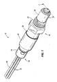
- Fig. 1 is a perspective view of an exhaust gas sensor embodying the present invention.
- Fig. 2 is a cross-sectional view of the exhaust gas sensor shown in Fig. 1 taken along line 2-2 of Fig. 1 .
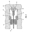
- Fig. 3 is a cross-sectional view of a subassembly of the exhaust gas sensor shown in Fig. 1 positioned within a mold fixture.
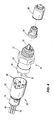
- Fig. 4 is a partially exploded perspective view of the components of the exhaust gas sensor shown in Fig. 1 .
- Fig. 1 illustrates an exhaust gas sensor 10 of the present invention.
- the sensor 10 includes a sensor subassembly 14 and an exit lead or wire harness subassembly 18.
- the illustrated sensor subassembly 14, or short sensor assembly includes a generally cylindrical metallic housing 22 configured to be threadably engaged with a threaded aperture of an exhaust pipe (not shown) or other component of an internal combustion engine used for automotive applications or non-automotive applications, such as motorcycles, snowmobiles, ATV's, lawnmowers, and the like.
- the illustrated sensor subassembly 14 also includes a ceramic material 26, a sensor element 30, a spacer 34, and a weld ring 38.
- the ceramic material 26 is molded to the housing 22 to encapsulate a middle portion of the sensor element 30 and to partially fill a bore 42 in the housing 22. During molding, the ceramic material 26 bonds to the housing 22 and the middle portion of the sensor element 30.
- the ceramic material 26 is a MICAVER ® HT mica material available from Saint-Gobain Quartz S.A.S. of France.
- the ceramic material 26 abuts the spacer 34, which in the illustrated embodiment is a sintered steatite bushing positioned in the housing 22 to act as a thermal barrier between the hot exhaust gases (e.g., greater than 700 degrees Celsius) and the ceramic material 26.
- the spacer 34 prevents the ceramic material 26 from entirely filling the bore 42 of the housing 22. In some low temperature applications, the spacer 34 can be eliminated, with the ceramic material 26 filling more of the bore 42.
- the ceramic material 26 also bonds to the weld ring 38 to support the weld ring 38 apart from the housing 22.
- the weld ring 38 provides a coupling area for the wire harness subassembly 18 as will be further described below.
- the sensor element 30 is a planar type sensor. Reference is made to U.S. Patent No. 6,164,120 , for discussion of additional features and operations of the planar type sensor not described herein.
- the sensor element 30 has a first end 46 extending out from one end of the ceramic material 26 and a second end 50 extending out from the opposite end of the ceramic material 26.
- the first end or exhaust side 46 of the sensor element 30 is surrounded by an inner protection tube 54 and an outer protection tube 58.
- the exhaust side 46 of the sensor element 30 is exposed to exhaust gas generated by the internal combustion engine.
- the second end or reference side 50 of the sensor element 30 is surrounded by the wire harness subassembly 18 and is exposed to reference air from the environment.
- the ceramic material 26 may also encapsulate the reference side 50 of the sensor element 30 and an air channel is molded or formed (e.g., by drilling) in the ceramic material 26 to allow communication of the sensor element 30 with the reference air.
- terminal pins or weld pins 62 electrically couple to the sensor element 30 by, for example, resistance welding or brazing.
- the ceramic material 26 partially encapsulates the terminal pins 62 such that one end of each terminal pin 62 extends from the ceramic material 26.
- the terminal pins 62 facilitate electrical contact between the wire harness subassembly 18 and the sensor element 30. In other embodiments, fewer or more terminal pins may be used.
- the wire harness subassembly 18 includes signal wires 66, heater wires 70, a cap 74, a seal grommet 78, and a sleeve 82.
- Weld terminals 86 are positioned on each wire 66, 70 and electrically couple with the corresponding terminal pins 62 of the sensor subassembly 14 by resistance welding or other suitable alternatives.
- the illustrated wire harness subassembly 18 includes four wires 66, 70 and weld terminals 86. However, it should be readily apparent to one skilled in the art that the wire harness subassembly 18 could be modified to include fewer or more wires 66, 70 and weld terminals 86 to match the number of terminal pins 62 of the sensor subassembly 14.
- the seal grommet 78 is positioned partially within a first end 90 of the sleeve 82 to support the wires 66, 70.
- the cap 74 secures the seal grommet 78 in place and couples to the first end 90 of the sleeve 82 by crimping or other suitable securing operations (e.g., brazing, welding, adhesives, etc.).
- the wire harness subassembly 18 couples to the weld ring 38 of the sensor subassembly 14 at a second end 94 of the sleeve 82 by press fitting and laser welding. Of course, other suitable securing operations may also be used.
- the exhaust gas sensor 10 is manufactured by positioning the sensor subassembly 14, minus the ceramic material 26, within a mold cavity 98 of a mold fixture 102, as shown in Fig. 3 .
- Liquefied or flowable ceramic material is injected (e.g., forced under pressure) into the mold cavity 98, overmolding a portion of the housing 22 and partially filling the bore 42 of the housing 22.
- the injected ceramic material also overmolds and partially surrounds the middle portion of the sensor element 30 and portions of the terminal pins 62. As the injected ceramic material cools, the ceramic material 26 hardens, thereby bonding to the housing 22.
- the ceramic material 26 bonds to and encapsulates the middle portion of the sensor element 30 and portions of the terminal pins 62, forming a hermetic seal about the middle portion of the sensor element 30 and the terminal pins 62.
- the weld ring 38 is positioned in the mold cavity 98 apart from the housing 22 such that as the injected ceramic material cools, the ceramic material 26 also bonds to the weld ring 38.
- the overmolded sensor subassembly 14 is removed from the mold cavity 98. The bonding of the ceramic material 26 to the housing 22, the sensor element 30, the terminal pins 62, and the weld ring 38 integrates the sensor subassembly 14 into a single, inseparable piece.
- Fig. 4 illustrates the overmolded sensor subassembly 14 separated from the wire harness subassembly 18.
- the inner protection tube 54 and the outer protection tube 58 are coupled to the housing 22 adjacent to the exhaust side 46 of the sensor element 30 by crimping, welding, or other suitable methods.
- the wire harness subassembly 18 components are assembled apart from the sensor subassembly 14, and are then coupled to the sensor subassembly 14 by first resistance welding the weld terminals 86 to the terminal pins 62 and then press fitting and laser welding the sleeve 82 to the weld ring 38.
- the illustrated exhaust gas sensor 10 reduces the total number of components required for construction.
- prior art exhaust gas sensors use steatite packing and boron nitride packing positioned about the middle portion of the sensor element to seal the reference side from the exhaust side. These packings are susceptible to characteristic shift downward (CSD) problems due to fuel vapor contamination.
- CSD characteristic shift downward
- both the steatite packing and boron nitride packing are replaced by the ceramic material 26, which acts as a hermetic seal and is less susceptible to CSD.
- the illustrated exhaust gas sensor 10 reduces the complexity and size of the manufacturing process required. Not only are the number of components required reduced, but the sensor element length may also be reduced compared to currently used exhaust gas sensors.
- the illustrated exhaust gas sensor 10 also provides an insulating barrier between the metal components (e.g., the housing 22 and the sleeve 82) to prevent excess conduction of heat to sensitive components, such as the seal grommet 78 and the wires 66, 70.
- the ceramic material 26 is a highly insulative barrier that prevents the transfer of heat from the exhaust side 46 of the sensor element 30 to the reference side 50.
- the ceramic material 26 improves thermal operating characteristics of the exhaust gas sensor 10 by breaking the metal to metal contact and having a low thermal conductivity (about 0.8 W/m.K) compared to steatite bushings (about 1.6 W/m ⁇ K) or stainless steel (about 14 W/m ⁇ K).
- the ceramic material 26 retains and isolates the terminal pins 62 to withstand high pull forces and vibrations. In other words, pull forces and vibrations that might otherwise cause separation between the sensor element 30 and the terminal pins 62 do not cause such separation in the illustrated exhaust gas sensor 10 due to the overmolded ceramic material 26.
Landscapes
- Chemical & Material Sciences (AREA)
- Life Sciences & Earth Sciences (AREA)
- Health & Medical Sciences (AREA)
- Physics & Mathematics (AREA)
- Chemical Kinetics & Catalysis (AREA)
- Electrochemistry (AREA)
- Molecular Biology (AREA)
- Analytical Chemistry (AREA)
- Biochemistry (AREA)
- General Health & Medical Sciences (AREA)
- General Physics & Mathematics (AREA)
- Immunology (AREA)
- Pathology (AREA)
- Measuring Oxygen Concentration In Cells (AREA)
- Investigating Or Analyzing Materials By The Use Of Fluid Adsorption Or Reactions (AREA)
Applications Claiming Priority (1)
| Application Number | Priority Date | Filing Date | Title |
|---|---|---|---|
| US11/613,530 US8147667B2 (en) | 2006-12-20 | 2006-12-20 | Exhaust gas sensor and method of manufacture |
Publications (3)
| Publication Number | Publication Date |
|---|---|
| EP1939615A2 EP1939615A2 (en) | 2008-07-02 |
| EP1939615A3 EP1939615A3 (en) | 2009-03-11 |
| EP1939615B1 true EP1939615B1 (en) | 2010-05-12 |
Family
ID=39415043
Family Applications (1)
| Application Number | Title | Priority Date | Filing Date |
|---|---|---|---|
| EP07024470A Not-in-force EP1939615B1 (en) | 2006-12-20 | 2007-12-18 | Exhaust gas sensor and method of manufacture |
Country Status (7)
| Country | Link |
|---|---|
| US (2) | US8147667B2 (enExample) |
| EP (1) | EP1939615B1 (enExample) |
| JP (1) | JP4956404B2 (enExample) |
| CN (1) | CN101206190B (enExample) |
| AT (1) | ATE467832T1 (enExample) |
| DE (1) | DE602007006403D1 (enExample) |
| ES (1) | ES2344231T3 (enExample) |
Families Citing this family (20)
| Publication number | Priority date | Publication date | Assignee | Title |
|---|---|---|---|---|
| US20100170794A1 (en) * | 2009-01-06 | 2010-07-08 | Gm Global Technology Operations, Inc. | Direct connect oxygen sensor |
| DE102009026418B4 (de) | 2009-05-22 | 2023-07-13 | Robert Bosch Gmbh | Konditionierung eines Sensorelements in einem Brennerprüferstand bei mindestens 1000°C und Konditionierungsstrom |
| CN102155280A (zh) * | 2010-02-12 | 2011-08-17 | 通用汽车环球科技运作公司 | 直接连接氧传感器 |
| US20110219795A1 (en) * | 2010-03-10 | 2011-09-15 | Chisun Ahn | Core assembly for air conditioner and air conditioner having the same |
| US9170132B2 (en) | 2010-05-05 | 2015-10-27 | Ysi Incorporated | Replaceable probe head having an operational amplifier |
| US8664938B2 (en) | 2010-05-05 | 2014-03-04 | Ysi Incorporated | Replaceable probe head |
| US8555482B2 (en) * | 2010-05-05 | 2013-10-15 | Ysi Incorporated | Process of assembling a probe |
| TWI486559B (zh) * | 2011-12-16 | 2015-06-01 | Ind Tech Res Inst | 感測裝置及其製作方法 |
| US9103251B2 (en) * | 2012-01-25 | 2015-08-11 | Cummins Inc. | Devices and methods for compliant aftertreatment component assembly |
| DE102012214251A1 (de) * | 2012-08-10 | 2014-02-13 | Robert Bosch Gmbh | Messfühler zur Bestimmung mindestens einer Eigenschaft eines Messgases in einem Messgasraum |
| DE102012214769B4 (de) * | 2012-08-20 | 2026-06-11 | Robert Bosch Gmbh | Verfahren zum Herstellen eines Messfühlers zur Bestimmung mindestens einer Eigenschaft eines Messgases |
| US9719884B2 (en) | 2012-12-20 | 2017-08-01 | Robert Bosch Gmbh | Intake gas sensor for internal combustion engine |
| US20140230545A1 (en) * | 2013-02-21 | 2014-08-21 | Amphenol Corporation | Sensor and method of making a sensor |
| CA2901139C (en) * | 2013-03-04 | 2021-10-19 | Scott Technologies, Inc. | Wire seal for a detector assembly |
| US9230706B1 (en) * | 2014-09-03 | 2016-01-05 | Prettl Electric Corp. | Process for forming wire harnesses |
| JP6303937B2 (ja) * | 2014-09-10 | 2018-04-04 | 住友電装株式会社 | 車輪速センサ |
| US10697305B2 (en) * | 2016-01-08 | 2020-06-30 | General Electric Company | Method for making hybrid ceramic/metal, ceramic/ceramic body by using 3D printing process |
| USD983059S1 (en) * | 2019-09-18 | 2023-04-11 | Ngk Insulators, Ltd. | Gas concentration detection sensor |
| JP7409232B2 (ja) * | 2020-06-03 | 2024-01-09 | 住友電装株式会社 | 複合成形部品 |
| US11845902B2 (en) * | 2020-06-23 | 2023-12-19 | Saudi Arabian Oil Company | Online analysis in a gas oil separation plant (GOSP) |
Family Cites Families (24)
| Publication number | Priority date | Publication date | Assignee | Title |
|---|---|---|---|---|
| DE2855012A1 (de) | 1978-12-20 | 1980-06-26 | Bosch Gmbh Robert | Elektrochemischer messfuehler fuer die bestimmung des sauerstoffgehaltes in gasen, insbesondere in abgasen |
| JPS5728241A (en) | 1980-07-28 | 1982-02-15 | Nippon Soken Inc | Gas component detector |
| US4535316A (en) | 1984-03-26 | 1985-08-13 | Allied Corporation | Heated titania oxygen sensor |
| DE3423590A1 (de) * | 1984-06-27 | 1986-01-09 | Robert Bosch Gmbh, 7000 Stuttgart | Sauerstoffmessfuehler |
| US4995256A (en) | 1989-03-20 | 1991-02-26 | Medical Graphics Corporation | Zirconia cell O2 sensor for respiratory gas analysis |
| US5389340A (en) | 1989-12-28 | 1995-02-14 | Tokuyama Corporation | Module and device for detecting NOX gas |
| EP0520528A1 (en) | 1991-06-10 | 1992-12-30 | General Motors Corporation | Electrochemical-type exhaust gas oxygen sensor having improved metal to ceramic seal |
| DE19605290C2 (de) * | 1996-02-14 | 1998-02-26 | Bosch Gmbh Robert | Meßfühler |
| JP3873390B2 (ja) | 1996-09-04 | 2007-01-24 | 株式会社デンソー | 酸素センサー |
| DE19707458A1 (de) | 1997-02-25 | 1998-08-27 | Bosch Gmbh Robert | Meßfühler und Verfahren zu dessen Herstellung |
| DE19707456A1 (de) * | 1997-02-25 | 1998-08-27 | Bosch Gmbh Robert | Meßfühler und Verfahren zu dessen Herstellung |
| DE19739435A1 (de) | 1997-09-09 | 1999-03-11 | Bosch Gmbh Robert | Meßfühler |
| JP2000241382A (ja) | 1999-02-22 | 2000-09-08 | Ngk Spark Plug Co Ltd | ガスセンサ |
| US6358383B2 (en) * | 1999-03-25 | 2002-03-19 | Delphi Technologies, Inc. | Exhaust constituent sensor and method of packaging the same |
| JP2004518942A (ja) | 1999-10-27 | 2004-06-24 | デルファイ・テクノロジーズ・インコーポレーテッド | ガスセンサーのターミナルアッセンブリ及び該アッセンブリを製造するための方法 |
| JP4423745B2 (ja) * | 2000-04-28 | 2010-03-03 | 株式会社デンソー | ガスセンサ |
| JP3800978B2 (ja) * | 2000-06-30 | 2006-07-26 | 株式会社デンソー | ガスセンサ及びその製造方法 |
| JP4542723B2 (ja) * | 2001-04-27 | 2010-09-15 | 日本特殊陶業株式会社 | センサ |
| JP4544779B2 (ja) * | 2001-05-21 | 2010-09-15 | 日本特殊陶業株式会社 | センサ |
| DE10222789B4 (de) | 2002-05-23 | 2006-12-07 | Robert Bosch Gmbh | Gasmeßfühler |
| US20040040370A1 (en) * | 2002-08-30 | 2004-03-04 | Takashi Kojima | Gas sensor having improved structure of electric connector |
| US7404883B2 (en) | 2004-04-12 | 2008-07-29 | Robert Bosch Gmbh | Insulation bushing assembly for an exhaust gas sensor |
| DE102004063085A1 (de) * | 2004-12-28 | 2006-07-06 | Robert Bosch Gmbh | Gasmessfühler |
| DE102005020792A1 (de) | 2005-05-04 | 2006-11-09 | Robert Bosch Gmbh | Messfühler zur Bestimmung der physikalischen Eigenschaft eines Messgases |
-
2006
- 2006-12-20 US US11/613,530 patent/US8147667B2/en not_active Expired - Fee Related
-
2007
- 2007-12-18 AT AT07024470T patent/ATE467832T1/de not_active IP Right Cessation
- 2007-12-18 ES ES07024470T patent/ES2344231T3/es active Active
- 2007-12-18 DE DE602007006403T patent/DE602007006403D1/de active Active
- 2007-12-18 EP EP07024470A patent/EP1939615B1/en not_active Not-in-force
- 2007-12-20 JP JP2007328524A patent/JP4956404B2/ja not_active Expired - Fee Related
- 2007-12-20 CN CN2007101646660A patent/CN101206190B/zh not_active Expired - Fee Related
-
2012
- 2012-02-29 US US13/407,884 patent/US8470163B2/en not_active Expired - Fee Related
Also Published As
| Publication number | Publication date |
|---|---|
| US8147667B2 (en) | 2012-04-03 |
| US20080149483A1 (en) | 2008-06-26 |
| EP1939615A3 (en) | 2009-03-11 |
| CN101206190B (zh) | 2013-03-06 |
| JP4956404B2 (ja) | 2012-06-20 |
| ES2344231T3 (es) | 2010-08-20 |
| US20120153535A1 (en) | 2012-06-21 |
| ATE467832T1 (de) | 2010-05-15 |
| US8470163B2 (en) | 2013-06-25 |
| DE602007006403D1 (de) | 2010-06-24 |
| EP1939615A2 (en) | 2008-07-02 |
| CN101206190A (zh) | 2008-06-25 |
| JP2008157950A (ja) | 2008-07-10 |
Similar Documents
| Publication | Publication Date | Title |
|---|---|---|
| US8470163B2 (en) | Exhaust gas sensor and method of manufacture | |
| EP2426486B1 (en) | Gas sensor and manufacturing method therefor | |
| US7553078B2 (en) | Temperature sensor and method for producing the same | |
| KR101010181B1 (ko) | 내연기관의 배기가스 시스템에 사용되는 저항 온도계용온도 센서 | |
| US20030146819A1 (en) | Sensor and manufacturing method thereof | |
| US4563568A (en) | Diesel engine glow plug | |
| US8702934B2 (en) | Gas sensor | |
| US8764955B2 (en) | Gas sensor | |
| US20140020446A1 (en) | Gas sensor | |
| US8256956B2 (en) | Temperature sensor | |
| KR20110079632A (ko) | 향상된 시일, 히터 프로브 어셈블리를 가진 예열 플러그 및 그 제조 방법 | |
| JP2000509823A (ja) | 測定センサのセンサエレメント用のシール装置 | |
| JP4317191B2 (ja) | 測定センサ | |
| CN103988022A (zh) | 压力测量预热塞 | |
| JP2005207721A (ja) | グロープラグ | |
| US6246000B1 (en) | Electric contact element | |
| US9557197B2 (en) | Gas sensor with a seal and method of making | |
| US20090050480A1 (en) | Exhaust gas sensor | |
| US20140355653A1 (en) | Exhaust gas temperature sensor | |
| US20110197666A1 (en) | Pressure Measuring Glow Plug | |
| JPH11258202A (ja) | ガス測定センサ | |
| US20090050479A1 (en) | Exhaust gas sensor | |
| JP4059222B2 (ja) | 温度センサ及び温度センサの製造方法 | |
| JP5519590B2 (ja) | 温度センサの製造方法及び温度センサ | |
| JP2012042376A (ja) | 温度センサ |
Legal Events
| Date | Code | Title | Description |
|---|---|---|---|
| PUAI | Public reference made under article 153(3) epc to a published international application that has entered the european phase |
Free format text: ORIGINAL CODE: 0009012 |
|
| AK | Designated contracting states |
Kind code of ref document: A2 Designated state(s): AT BE BG CH CY CZ DE DK EE ES FI FR GB GR HU IE IS IT LI LT LU LV MC MT NL PL PT RO SE SI SK TR |
|
| AX | Request for extension of the european patent |
Extension state: AL BA HR MK RS |
|
| PUAL | Search report despatched |
Free format text: ORIGINAL CODE: 0009013 |
|
| AK | Designated contracting states |
Kind code of ref document: A3 Designated state(s): AT BE BG CH CY CZ DE DK EE ES FI FR GB GR HU IE IS IT LI LT LU LV MC MT NL PL PT RO SE SI SK TR |
|
| AX | Request for extension of the european patent |
Extension state: AL BA HR MK RS |
|
| 17P | Request for examination filed |
Effective date: 20090911 |
|
| AKX | Designation fees paid |
Designated state(s): AT BE BG CH CY CZ DE DK EE ES FI FR GB GR HU IE IS IT LI LT LU LV MC MT NL PL PT RO SE SI SK TR |
|
| GRAP | Despatch of communication of intention to grant a patent |
Free format text: ORIGINAL CODE: EPIDOSNIGR1 |
|
| GRAS | Grant fee paid |
Free format text: ORIGINAL CODE: EPIDOSNIGR3 |
|
| GRAA | (expected) grant |
Free format text: ORIGINAL CODE: 0009210 |
|
| AK | Designated contracting states |
Kind code of ref document: B1 Designated state(s): AT BE BG CH CY CZ DE DK EE ES FI FR GB GR HU IE IS IT LI LT LU LV MC MT NL PL PT RO SE SI SK TR |
|
| REG | Reference to a national code |
Ref country code: GB Ref legal event code: FG4D |
|
| REG | Reference to a national code |
Ref country code: CH Ref legal event code: EP |
|
| REG | Reference to a national code |
Ref country code: IE Ref legal event code: FG4D |
|
| REF | Corresponds to: |
Ref document number: 602007006403 Country of ref document: DE Date of ref document: 20100624 Kind code of ref document: P |
|
| REG | Reference to a national code |
Ref country code: ES Ref legal event code: FG2A Ref document number: 2344231 Country of ref document: ES Kind code of ref document: T3 |
|
| REG | Reference to a national code |
Ref country code: NL Ref legal event code: VDEP Effective date: 20100512 |
|
| LTIE | Lt: invalidation of european patent or patent extension |
Effective date: 20100512 |
|
| PG25 | Lapsed in a contracting state [announced via postgrant information from national office to epo] |
Ref country code: LT Free format text: LAPSE BECAUSE OF FAILURE TO SUBMIT A TRANSLATION OF THE DESCRIPTION OR TO PAY THE FEE WITHIN THE PRESCRIBED TIME-LIMIT Effective date: 20100512 Ref country code: NL Free format text: LAPSE BECAUSE OF FAILURE TO SUBMIT A TRANSLATION OF THE DESCRIPTION OR TO PAY THE FEE WITHIN THE PRESCRIBED TIME-LIMIT Effective date: 20100512 Ref country code: SE Free format text: LAPSE BECAUSE OF FAILURE TO SUBMIT A TRANSLATION OF THE DESCRIPTION OR TO PAY THE FEE WITHIN THE PRESCRIBED TIME-LIMIT Effective date: 20100512 |
|
| PG25 | Lapsed in a contracting state [announced via postgrant information from national office to epo] |
Ref country code: LV Free format text: LAPSE BECAUSE OF FAILURE TO SUBMIT A TRANSLATION OF THE DESCRIPTION OR TO PAY THE FEE WITHIN THE PRESCRIBED TIME-LIMIT Effective date: 20100512 Ref country code: SI Free format text: LAPSE BECAUSE OF FAILURE TO SUBMIT A TRANSLATION OF THE DESCRIPTION OR TO PAY THE FEE WITHIN THE PRESCRIBED TIME-LIMIT Effective date: 20100512 Ref country code: AT Free format text: LAPSE BECAUSE OF FAILURE TO SUBMIT A TRANSLATION OF THE DESCRIPTION OR TO PAY THE FEE WITHIN THE PRESCRIBED TIME-LIMIT Effective date: 20100512 Ref country code: FI Free format text: LAPSE BECAUSE OF FAILURE TO SUBMIT A TRANSLATION OF THE DESCRIPTION OR TO PAY THE FEE WITHIN THE PRESCRIBED TIME-LIMIT Effective date: 20100512 Ref country code: IS Free format text: LAPSE BECAUSE OF FAILURE TO SUBMIT A TRANSLATION OF THE DESCRIPTION OR TO PAY THE FEE WITHIN THE PRESCRIBED TIME-LIMIT Effective date: 20100912 |
|
| PG25 | Lapsed in a contracting state [announced via postgrant information from national office to epo] |
Ref country code: PL Free format text: LAPSE BECAUSE OF FAILURE TO SUBMIT A TRANSLATION OF THE DESCRIPTION OR TO PAY THE FEE WITHIN THE PRESCRIBED TIME-LIMIT Effective date: 20100512 Ref country code: CY Free format text: LAPSE BECAUSE OF FAILURE TO SUBMIT A TRANSLATION OF THE DESCRIPTION OR TO PAY THE FEE WITHIN THE PRESCRIBED TIME-LIMIT Effective date: 20100526 |
|
| PG25 | Lapsed in a contracting state [announced via postgrant information from national office to epo] |
Ref country code: GR Free format text: LAPSE BECAUSE OF FAILURE TO SUBMIT A TRANSLATION OF THE DESCRIPTION OR TO PAY THE FEE WITHIN THE PRESCRIBED TIME-LIMIT Effective date: 20100813 Ref country code: EE Free format text: LAPSE BECAUSE OF FAILURE TO SUBMIT A TRANSLATION OF THE DESCRIPTION OR TO PAY THE FEE WITHIN THE PRESCRIBED TIME-LIMIT Effective date: 20100512 Ref country code: DK Free format text: LAPSE BECAUSE OF FAILURE TO SUBMIT A TRANSLATION OF THE DESCRIPTION OR TO PAY THE FEE WITHIN THE PRESCRIBED TIME-LIMIT Effective date: 20100512 Ref country code: PT Free format text: LAPSE BECAUSE OF FAILURE TO SUBMIT A TRANSLATION OF THE DESCRIPTION OR TO PAY THE FEE WITHIN THE PRESCRIBED TIME-LIMIT Effective date: 20100913 |
|
| PG25 | Lapsed in a contracting state [announced via postgrant information from national office to epo] |
Ref country code: SK Free format text: LAPSE BECAUSE OF FAILURE TO SUBMIT A TRANSLATION OF THE DESCRIPTION OR TO PAY THE FEE WITHIN THE PRESCRIBED TIME-LIMIT Effective date: 20100512 Ref country code: RO Free format text: LAPSE BECAUSE OF FAILURE TO SUBMIT A TRANSLATION OF THE DESCRIPTION OR TO PAY THE FEE WITHIN THE PRESCRIBED TIME-LIMIT Effective date: 20100512 Ref country code: CZ Free format text: LAPSE BECAUSE OF FAILURE TO SUBMIT A TRANSLATION OF THE DESCRIPTION OR TO PAY THE FEE WITHIN THE PRESCRIBED TIME-LIMIT Effective date: 20100512 Ref country code: BE Free format text: LAPSE BECAUSE OF FAILURE TO SUBMIT A TRANSLATION OF THE DESCRIPTION OR TO PAY THE FEE WITHIN THE PRESCRIBED TIME-LIMIT Effective date: 20100512 |
|
| PLBE | No opposition filed within time limit |
Free format text: ORIGINAL CODE: 0009261 |
|
| STAA | Information on the status of an ep patent application or granted ep patent |
Free format text: STATUS: NO OPPOSITION FILED WITHIN TIME LIMIT |
|
| 26N | No opposition filed |
Effective date: 20110215 |
|
| REG | Reference to a national code |
Ref country code: DE Ref legal event code: R097 Ref document number: 602007006403 Country of ref document: DE Effective date: 20110214 |
|
| PG25 | Lapsed in a contracting state [announced via postgrant information from national office to epo] |
Ref country code: MC Free format text: LAPSE BECAUSE OF NON-PAYMENT OF DUE FEES Effective date: 20101231 |
|
| PG25 | Lapsed in a contracting state [announced via postgrant information from national office to epo] |
Ref country code: IE Free format text: LAPSE BECAUSE OF NON-PAYMENT OF DUE FEES Effective date: 20101218 |
|
| PG25 | Lapsed in a contracting state [announced via postgrant information from national office to epo] |
Ref country code: MT Free format text: LAPSE BECAUSE OF FAILURE TO SUBMIT A TRANSLATION OF THE DESCRIPTION OR TO PAY THE FEE WITHIN THE PRESCRIBED TIME-LIMIT Effective date: 20100512 Ref country code: IT Free format text: LAPSE BECAUSE OF NON-PAYMENT OF DUE FEES Effective date: 20101218 |
|
| REG | Reference to a national code |
Ref country code: CH Ref legal event code: PL |
|
| PG25 | Lapsed in a contracting state [announced via postgrant information from national office to epo] |
Ref country code: LU Free format text: LAPSE BECAUSE OF NON-PAYMENT OF DUE FEES Effective date: 20101218 Ref country code: BG Free format text: LAPSE BECAUSE OF FAILURE TO SUBMIT A TRANSLATION OF THE DESCRIPTION OR TO PAY THE FEE WITHIN THE PRESCRIBED TIME-LIMIT Effective date: 20100512 Ref country code: HU Free format text: LAPSE BECAUSE OF FAILURE TO SUBMIT A TRANSLATION OF THE DESCRIPTION OR TO PAY THE FEE WITHIN THE PRESCRIBED TIME-LIMIT Effective date: 20101113 |
|
| PG25 | Lapsed in a contracting state [announced via postgrant information from national office to epo] |
Ref country code: LI Free format text: LAPSE BECAUSE OF NON-PAYMENT OF DUE FEES Effective date: 20111231 Ref country code: TR Free format text: LAPSE BECAUSE OF FAILURE TO SUBMIT A TRANSLATION OF THE DESCRIPTION OR TO PAY THE FEE WITHIN THE PRESCRIBED TIME-LIMIT Effective date: 20100512 Ref country code: CH Free format text: LAPSE BECAUSE OF NON-PAYMENT OF DUE FEES Effective date: 20111231 |
|
| PG25 | Lapsed in a contracting state [announced via postgrant information from national office to epo] |
Ref country code: BG Free format text: LAPSE BECAUSE OF FAILURE TO SUBMIT A TRANSLATION OF THE DESCRIPTION OR TO PAY THE FEE WITHIN THE PRESCRIBED TIME-LIMIT Effective date: 20100812 |
|
| REG | Reference to a national code |
Ref country code: FR Ref legal event code: PLFP Year of fee payment: 9 |
|
| REG | Reference to a national code |
Ref country code: FR Ref legal event code: PLFP Year of fee payment: 10 |
|
| REG | Reference to a national code |
Ref country code: FR Ref legal event code: PLFP Year of fee payment: 11 |
|
| PGFP | Annual fee paid to national office [announced via postgrant information from national office to epo] |
Ref country code: GB Payment date: 20181219 Year of fee payment: 12 Ref country code: IT Payment date: 20181218 Year of fee payment: 12 |
|
| PGFP | Annual fee paid to national office [announced via postgrant information from national office to epo] |
Ref country code: FR Payment date: 20190326 Year of fee payment: 15 |
|
| GBPC | Gb: european patent ceased through non-payment of renewal fee |
Effective date: 20191218 |
|
| PG25 | Lapsed in a contracting state [announced via postgrant information from national office to epo] |
Ref country code: IT Free format text: LAPSE BECAUSE OF NON-PAYMENT OF DUE FEES Effective date: 20191218 Ref country code: GB Free format text: LAPSE BECAUSE OF NON-PAYMENT OF DUE FEES Effective date: 20191218 |
|
| REG | Reference to a national code |
Ref country code: ES Ref legal event code: FD2A Effective date: 20210526 |
|
| PGFP | Annual fee paid to national office [announced via postgrant information from national office to epo] |
Ref country code: DE Payment date: 20210217 Year of fee payment: 14 |
|
| PG25 | Lapsed in a contracting state [announced via postgrant information from national office to epo] |
Ref country code: FR Free format text: LAPSE BECAUSE OF NON-PAYMENT OF DUE FEES Effective date: 20191231 |
|
| PG25 | Lapsed in a contracting state [announced via postgrant information from national office to epo] |
Ref country code: ES Free format text: LAPSE BECAUSE OF NON-PAYMENT OF DUE FEES Effective date: 20191219 |
|
| REG | Reference to a national code |
Ref country code: DE Ref legal event code: R119 Ref document number: 602007006403 Country of ref document: DE |
|
| PG25 | Lapsed in a contracting state [announced via postgrant information from national office to epo] |
Ref country code: DE Free format text: LAPSE BECAUSE OF NON-PAYMENT OF DUE FEES Effective date: 20220701 |