EP1937978B1 - Kühlerlüfter für ein kraftfahrzeug - Google Patents
Kühlerlüfter für ein kraftfahrzeug Download PDFInfo
- Publication number
- EP1937978B1 EP1937978B1 EP06793354A EP06793354A EP1937978B1 EP 1937978 B1 EP1937978 B1 EP 1937978B1 EP 06793354 A EP06793354 A EP 06793354A EP 06793354 A EP06793354 A EP 06793354A EP 1937978 B1 EP1937978 B1 EP 1937978B1
- Authority
- EP
- European Patent Office
- Prior art keywords
- fan
- inner rotor
- hub
- guide shaft
- radiator
- Prior art date
- Legal status (The legal status is an assumption and is not a legal conclusion. Google has not performed a legal analysis and makes no representation as to the accuracy of the status listed.)
- Not-in-force
Links
Images




Classifications
-
- F—MECHANICAL ENGINEERING; LIGHTING; HEATING; WEAPONS; BLASTING
- F04—POSITIVE - DISPLACEMENT MACHINES FOR LIQUIDS; PUMPS FOR LIQUIDS OR ELASTIC FLUIDS
- F04D—NON-POSITIVE-DISPLACEMENT PUMPS
- F04D25/00—Pumping installations or systems
- F04D25/02—Units comprising pumps and their driving means
- F04D25/06—Units comprising pumps and their driving means the pump being electrically driven
- F04D25/0606—Units comprising pumps and their driving means the pump being electrically driven the electric motor being specially adapted for integration in the pump
-
- F—MECHANICAL ENGINEERING; LIGHTING; HEATING; WEAPONS; BLASTING
- F04—POSITIVE - DISPLACEMENT MACHINES FOR LIQUIDS; PUMPS FOR LIQUIDS OR ELASTIC FLUIDS
- F04D—NON-POSITIVE-DISPLACEMENT PUMPS
- F04D25/00—Pumping installations or systems
- F04D25/02—Units comprising pumps and their driving means
- F04D25/06—Units comprising pumps and their driving means the pump being electrically driven
-
- F—MECHANICAL ENGINEERING; LIGHTING; HEATING; WEAPONS; BLASTING
- F04—POSITIVE - DISPLACEMENT MACHINES FOR LIQUIDS; PUMPS FOR LIQUIDS OR ELASTIC FLUIDS
- F04D—NON-POSITIVE-DISPLACEMENT PUMPS
- F04D25/00—Pumping installations or systems
- F04D25/02—Units comprising pumps and their driving means
- F04D25/08—Units comprising pumps and their driving means the working fluid being air, e.g. for ventilation
-
- F—MECHANICAL ENGINEERING; LIGHTING; HEATING; WEAPONS; BLASTING
- F04—POSITIVE - DISPLACEMENT MACHINES FOR LIQUIDS; PUMPS FOR LIQUIDS OR ELASTIC FLUIDS
- F04D—NON-POSITIVE-DISPLACEMENT PUMPS
- F04D25/00—Pumping installations or systems
- F04D25/02—Units comprising pumps and their driving means
- F04D25/08—Units comprising pumps and their driving means the working fluid being air, e.g. for ventilation
- F04D25/082—Units comprising pumps and their driving means the working fluid being air, e.g. for ventilation the unit having provision for cooling the motor
-
- F—MECHANICAL ENGINEERING; LIGHTING; HEATING; WEAPONS; BLASTING
- F04—POSITIVE - DISPLACEMENT MACHINES FOR LIQUIDS; PUMPS FOR LIQUIDS OR ELASTIC FLUIDS
- F04D—NON-POSITIVE-DISPLACEMENT PUMPS
- F04D29/00—Details, component parts, or accessories
- F04D29/26—Rotors specially for elastic fluids
- F04D29/32—Rotors specially for elastic fluids for axial flow pumps
- F04D29/325—Rotors specially for elastic fluids for axial flow pumps for axial flow fans
- F04D29/329—Details of the hub
-
- F—MECHANICAL ENGINEERING; LIGHTING; HEATING; WEAPONS; BLASTING
- F04—POSITIVE - DISPLACEMENT MACHINES FOR LIQUIDS; PUMPS FOR LIQUIDS OR ELASTIC FLUIDS
- F04D—NON-POSITIVE-DISPLACEMENT PUMPS
- F04D29/00—Details, component parts, or accessories
- F04D29/58—Cooling; Heating; Diminishing heat transfer
- F04D29/5806—Cooling the drive system
-
- H—ELECTRICITY
- H02—GENERATION; CONVERSION OR DISTRIBUTION OF ELECTRIC POWER
- H02K—DYNAMO-ELECTRIC MACHINES
- H02K1/00—Details of the magnetic circuit
- H02K1/06—Details of the magnetic circuit characterised by the shape, form or construction
- H02K1/12—Stationary parts of the magnetic circuit
- H02K1/18—Means for mounting or fastening magnetic stationary parts on to, or to, the stator structures
- H02K1/185—Means for mounting or fastening magnetic stationary parts on to, or to, the stator structures to outer stators
-
- H—ELECTRICITY
- H02—GENERATION; CONVERSION OR DISTRIBUTION OF ELECTRIC POWER
- H02K—DYNAMO-ELECTRIC MACHINES
- H02K11/00—Structural association of dynamo-electric machines with electric components or with devices for shielding, monitoring or protection
- H02K11/30—Structural association with control circuits or drive circuits
- H02K11/33—Drive circuits, e.g. power electronics
-
- H—ELECTRICITY
- H02—GENERATION; CONVERSION OR DISTRIBUTION OF ELECTRIC POWER
- H02K—DYNAMO-ELECTRIC MACHINES
- H02K5/00—Casings; Enclosures; Supports
- H02K5/04—Casings or enclosures characterised by the shape, form or construction thereof
- H02K5/16—Means for supporting bearings, e.g. insulating supports or means for fitting bearings in the bearing-shields
- H02K5/173—Means for supporting bearings, e.g. insulating supports or means for fitting bearings in the bearing-shields using bearings with rolling contact, e.g. ball bearings
- H02K5/1735—Means for supporting bearings, e.g. insulating supports or means for fitting bearings in the bearing-shields using bearings with rolling contact, e.g. ball bearings radially supporting the rotary shaft at only one end of the rotor
-
- H—ELECTRICITY
- H02—GENERATION; CONVERSION OR DISTRIBUTION OF ELECTRIC POWER
- H02K—DYNAMO-ELECTRIC MACHINES
- H02K9/00—Arrangements for cooling or ventilating
- H02K9/02—Arrangements for cooling or ventilating by ambient air flowing through the machine
- H02K9/04—Arrangements for cooling or ventilating by ambient air flowing through the machine having means for generating a flow of cooling medium
- H02K9/06—Arrangements for cooling or ventilating by ambient air flowing through the machine having means for generating a flow of cooling medium with fans or impellers driven by the machine shaft
-
- H—ELECTRICITY
- H02—GENERATION; CONVERSION OR DISTRIBUTION OF ELECTRIC POWER
- H02K—DYNAMO-ELECTRIC MACHINES
- H02K1/00—Details of the magnetic circuit
- H02K1/06—Details of the magnetic circuit characterised by the shape, form or construction
- H02K1/22—Rotating parts of the magnetic circuit
- H02K1/32—Rotating parts of the magnetic circuit with channels or ducts for flow of cooling medium
-
- H—ELECTRICITY
- H02—GENERATION; CONVERSION OR DISTRIBUTION OF ELECTRIC POWER
- H02K—DYNAMO-ELECTRIC MACHINES
- H02K7/00—Arrangements for handling mechanical energy structurally associated with dynamo-electric machines, e.g. structural association with mechanical driving motors or auxiliary dynamo-electric machines
- H02K7/14—Structural association with mechanical loads, e.g. with hand-held machine tools or fans
Definitions
- the invention relates to a radiator fan for a motor vehicle, with a fan wheel and with a brushless fan motor for driving the fan wheel, wherein the fan motor has an internal rotor.
- both rotor and stator and the motor electronics are enclosed in a housing between a front and a rear bearing plate.
- the fan is located outside the housing and connected to the fan motor via the drive shaft.
- the drive shaft is guided in the front and the rear end plate of the housing.
- the German Utility Model 94 04147 U1 which is to be seen as the closest prior art, discloses an axial fan in which the fan wheel is connected directly to a rotor of the fan designed as an internal rotor. At the impeller opposite end face of the rotor an additional, smaller impeller is provided to generate an air flow through an air gap formed by the stator and rotor, whereby the windings of the rotor and the stator cooled and moisture deposits are avoided in the air gap of the motor.
- German patent application DE 42 14 160 A1 describes a fan in which the fan wheel carries the rotor of the drive without a drive shaft is used.
- An object of the present invention is to reduce the size of a radiator fan while maintaining the same performance.
- a radiator fan for a motor vehicle, with a fan and a brushless fan motor for driving the fan, wherein the fan motor has an inner rotor, wherein the fan has a fan hub and the fan hub is connected directly to the inner rotor and wherein the fan hub to its internal rotor facing the inside has a number of fan blades.
- the fan blades are arranged in two groups, one group serving primarily for generating an air flow through an open central region of the inner rotor, while the other group is used primarily for generating an air flow through the slot slots of the stator.
- a front end shield is not needed. Since the fan wheel is driven directly via the internal rotor, no drive shaft is required. Instead, a guide shaft may be provided for holding the inner rotor.
- the invention reduces the weight of the fan motor and thus of the entire radiator fan. At the same time results in a reduction of manufacturing and assembly costs and - by reducing the number of parts - an increase in reliability.
- the invention allows despite the reduced size of the radiator fan significantly improved heat dissipation of fan motor and engine electronics. Due to the reduced length shorten the ways that have to cover the cooling air inside the fan motor. This reduces the pressure drop, so that the effectiveness of the cooling is increased by forced convection heat.
- the fan hub has a number of fan blades on its inner side facing the inner rotor.
- the arrangement of the fan blades in two groups a particularly effective cooling of the engine electronics in the housing on the one hand and cooling of the windings on the other hand, and thus an improved self-cooling of the fan motor is achieved.
- radiator fans for automotive applications can be provided which are improved in terms of performance, reliability and efficiency over the prior art solutions.
- the two groups of fan blades are spaced apart from one another in such a way that they can accommodate the single tooth windings projecting axially out of the stator, the axial length can be reduced even further.
- Constructively advantageous embodiments include: an inner rotor with a guide opening for receiving the guide shaft, which is mounted in a rear end plate of a housing; a bearing of the guide shaft in or on the inner rotor in conjunction with a determination of the guide shaft in a housing and a bearing of the guide shaft in or on the fan hub in conjunction with a determination of the guide shaft in a housing.
- a ball bearing and a plain bearing or two plain bearings are used.
- FIG. 1 a radiator fan 101 known from the prior art is shown, which has a fan motor 102 with an internal rotor 103.
- the aluminum housing 107 which also serves as a cooling element, has a front end shield 150 and a rear end shield 108, which form a closed interior 151 for receiving the stator 114 and the inner rotor 103.
- the engine electronics is arranged in the rear end shield 108.
- Both in the front bearing plate 150 and in the rear end plate 108 bearing 117 for supporting a drive shaft 152 are provided.
- Connected to the drive shaft 152 is the inner rotor 103 with permanent magnets 126.
- the stator 114 has a copper winding 128.
- the fan hub 105 of the fan wheel is attached.
- the cooling air stream 134 extends along the engine electronics, through the slot slots 138 of the stator 114 and through openings in the front bearing plate 150 into the open.
- the axial length 116 is determined by the lengths of the rear end plate 108, stator 114 and inner rotor 103, front end shield 150 and fan hub 105 and the associated gaps.
- the illustrated radiator fan 1 has a fan motor 2 with an inner rotor 3.
- the fan 4 has a fan hub 5 and a number of radially extending from the fan hub 5 outwardly extending fan blades 6. It can be designed, for example, as an axial fan.
- the serving as a cooling element aluminum housing 7 consists essentially of a rear end plate 8, in which the motor electronics 9 with components such as electrolytic capacitors 11, MOSFETs, processor, etc., is arranged.
- the bearing plate 8 is provided with a plurality of cooling fins 12 and passage openings 13 for cooling air. These are used for heat dissipation by heat conduction, heat radiation and convection heat.
- a stand 14 is attached to a retaining ring 15, which is formed as an integral part of the housing 7 (see. FIG. 7 ) and extends from the end plate 8 in the direction of fan 4. In the direction of the fan hub 5 of the fan 4, the housing 7 is open.
- the stator 14 and the inner rotor 3 are thus arranged directly adjacent to the fan wheel 4 without a separating housing part.
- the fan hub 5 is connected directly to the inner rotor 3.
- the transmission of the torque is thus directly from the inner rotor 3 on the fan 4.
- the axial length 16 of the radiator fan 1 is characterized in relation to the in FIG. 1 significantly reduced solution shown.
- the production costs are lower than in conventional inner rotor solutions, since neither a mechanically highly resilient attachment of the inner rotor 3 to a drive shaft, nor a mechanically highly resilient attachment of the fan wheel 4 on the drive shaft is required.
- connection of the Lüfternäbe 5 with the inner rotor 3 can be done in various ways, for example by Screwing, injecting, pressing on by making a press fit or the like.
- two centrally arranged ball bearings 17 are provided for supporting a guide shaft 18.
- the guide axis 18 is not assigned a drive function.
- the guide shaft 18 serves to guide the inner rotor 3 and the Lüfternabe 5.
- a different bearing configuration can be used, for example using a ball bearing and a plain bearing or using two plain bearings.
- the or the bearing can also be provided in or on the inner rotor 3, wherein the guide shaft 18 is then fixed in the housing 7.
- the bearing or bearings may also be provided in or on the fan hub 5, wherein the guide shaft 18 is again fixed in the housing 7.
- the inner rotor 3 constructed from a number of iron sheets has a central guide element 19 with a guide opening 21 for receiving the guide shaft 18.
- the guide element 19 is surrounded by a central region 22, which is designed to be open and suitable for the passage of cooling air.
- the central region 22 is arranged in a region of the inner rotor 3, which is not magnetically effective. Due to the lack of rotor material, this results in a sometimes considerable reduction in weight of the inner rotor 3 at the same power of the fan motor. 2
- the central region 22 is surrounded by an outer ring 23 which forms the actual "iron” of the fan motor 2 and is connected to the central guide element 19 via four retaining and connecting struts 24.
- an outer ring 23 which forms the actual "iron” of the fan motor 2 and is connected to the central guide element 19 via four retaining and connecting struts 24.
- the permanent magnets are preferably around rare earth magnets. These are connected to the outer ring 23 by a plastic extrusion 27.
- the stator 14 has a number of copper windings 28 in the form of Einzel leopardbewicklonne.
- the cup-like around the retaining ring 15 of the housing 7 inverted fan hub 5 has on its inner rotor 3 facing inside 29 a number of fan blades 31, 32, which are arranged so that they generate in a rotation of the impeller 4 in the direction of rotation 33 cooling air flows.
- the fan blades 31, 32 are arranged in two groups.
- the one group of fan blades 31 is arranged near the guide axis 18 and serves primarily for generating an air flow 34 through the open central region 22 of the inner rotor 3 and thus especially for cooling the fan 4 open in the bearing plate 8 arranged engine electronics 9.
- the individual fan blades 31 form a radial fan. They are executed opposite to the direction of rotation 33 (that is to say “backwards") bent and extend, starting from the central guide opening 35 of the fan hub 5, in the direction of the hub circumference 36.
- the other group of fan blades 32 is spaced from the guide shaft 18 at the hub periphery 36 and along the cup-like extension of the fan hub 5 and serves primarily to create an airflow 37 through the slot slots 38 of the stator 14.
- This cooling air flow serves to directly cool the windings 28 of the stator Stator 14 and beyond also for cooling the engine electronics 9.
- the individual fan blades 32 are running and extend starting from the hub periphery 36 in the direction of rotation 33 obliquely inwards.
- the electromagnetic properties of the fan motor 2 are coordinated such that a low degree of filling of the grooves is present such that one for a Cooling sufficient cooling air flow through the groove slots 38 can flow therethrough.
- the two groups of fan blades 31, 32 are spaced apart.
- the distance 39 serves to receive the winding ends 41 of the windings 28 of the stator 14.
- the axial length 16 of the radiator fan 1 is further reduced.
- a particularly high cooling capacity is achieved because of the achievable higher air velocities in that the distances between the windings 28 and the adjacent ends of the fan blades 31, 32 are very small.
- the entire motor electronics 9 is arranged for easy mounting on the fan hub 5 facing the front 42 of the bearing plate 8.
- the motor electronics 9 for thermal reasons also completely or partially on the fan hub 5 facing away from the rear side 43 of the bearing plate 8 may be arranged.
Landscapes
- Engineering & Computer Science (AREA)
- Mechanical Engineering (AREA)
- General Engineering & Computer Science (AREA)
- Power Engineering (AREA)
- Microelectronics & Electronic Packaging (AREA)
- Physics & Mathematics (AREA)
- Thermal Sciences (AREA)
- Motor Or Generator Cooling System (AREA)
- Structures Of Non-Positive Displacement Pumps (AREA)
Description
- Die Erfindung betrifft einen Kühlerlüfter für ein Kraftfahrzeug, mit einem Lüfterrad und mit einem bürstenlosen Lüftermotor zum Antrieb des Lüfterrades, wobei der Lüftermotor einen Innenläufer aufweist.
- Im Automobilbereich ist der Einsatz von bürstenlosen Lüftermotoren bekannt. Diese werden u.a. für Kühlerlüfter zur Kühlung des Verbrennungsmotors und für Kühlerlüfter für Klimaanlagen und Innenraumbelüftungen verwendet.
- Bei bekannten bürstenlosen Lüftermotoren mit Innenläufern sind sowohl Läufer und Ständer als auch die Motorelektronik in einem Gehäuse zwischen einem vorderen und einem hinteren Lagerschild eingeschlossen. Das Lüfterrad ist außerhalb des Gehäuses angeordnet und mit dem Lüftermotor über die Antriebswelle verbunden. Die Antriebswelle wird dabei in dem vorderen und dem hinteren Lagerschild des Gehäuses geführt.
- Die deutsche Gebrauchsmusterschrift
94 04147 U1 , die als nächstliegender Stand der Technik augesehen wird offenbart einen Axiallüfter, bei dem das Lüfterrad direkt mit einem als Innenläufer ausgebildeten Rotor des Lüfters verbunden ist. An der dem Lüfterrad entgegengesetzt angeordneten Stirnseite des Rotors ist zur Erzeugung eines Luftstromes durch einen von Stator und Rotor gebildeten Luftspalt ein zusätzliches, kleineres Lüfterrad vorgesehen, wodurch die Wicklungen des Rotors und des Stators gekühlt und Feuchtigkeitsablagerungen im Luftspalt des Motors vermieden werden. - Die deutsche Offenlegungsschrift
DE 42 14 160 A1 beschreibt einen Lüfter, bei dem das Lüfterrad den Rotor des Antriebs trägt, ohne das dabei eine Antriebswelle verwendet wird. - Eine Aufgabe der vorliegenden Erfindung ist es, die Baugröße eines Kühlerlüfter bei gleicher Leistung zu verringern.
- Diese Aufgabe wird durch einen Kühlerlüfter nach Anspruch 1 gelöst. Danach ist vorgesehen: ein Kühlerlüfter für ein Kraftfahrzeug, mit einem Lüfterrad und mit einem bürstenlosen Lüftermotor zum Antrieb des Lüfterrades, wobei der Lüftermotor einen Innenläufer aufweist, wobei das Lüfterrad eine Lüfternabe aufweist und die Lüfternabe direkt mit dem Innenläufer verbunden ist und wobei die Lüfternabe an ihrer dem Innenläufer zugewandten Innenseite eine Anzahl von Lüfterblättern aufweist. Erfindungsgemäß sind die Lüfterblätter in zwei Gruppen angeordnet, wobei die eine Gruppe vorwiegend zur Erzeugung eines Luftstromes durch einen offenen Zentralbereich des Innenläufers dient, während die andere Gruppe vorwiegend zur Erzeugung eines Luftstromes durch die Nutenschlitze des Ständers dient.
- Durch diese konstruktive Ausgestaltung wird zum einen eine deutliche Verringerung der axialen Baulänge erzielt. Ein vorderes Lagerschild wird nicht benötigt. Da der Antrieb des Lüfterrades direkt über den Innenläufer erfolgt, wird keine Antriebswelle benötigt. Statt dessen kann zur Halterung des Innenläufers eine Führungsachse vorgesehen sein.
- Darüber hinaus wird durch die Erfindung das Gewicht des Lüftermotors und damit des gesamten Kühlerlüfters verringert. Zugleich ergibt sich eine Reduzierung der Herstellungs- und Montagekosten sowie - durch die Verringerung der Teileanzahl - eine Erhöhung der Zuverlässigkeit.
- Zudem ermöglicht die Erfindung trotz der reduzierten Baugröße des Kühlerlüfters eine deutlich verbesserte Wärmeabfuhr von Lüftermotor und Motorelektronik. Durch die verringerte Baulänge verkürzen sich die Wege, welche die Kühlluft im Inneren des Lüftermotors zurückzulegen haben. Dadurch verringert sich der Druckabfall, so dass die Effektivität der Kühlung durch erzwungene Wärmekonvektion erhöht wird.
- Aufgrund der direkten Verbindung des Lüfterrades über seine Lüfternabe mit dem Innenläufer ist eine maximale Verringerung der axialen Baulänge des Kühlerlüfters möglich. So läßt sich eine besonders kompakte Bauform erreichen.
- Um eine direkte Anbindung des Lüfterrades zu ermöglichen, ist ein in Richtung Lüfterrad offenes Gehäuse vorgesehen. Da kein vorderes Lagerschild das Gehäuse abschließt, ist eine unmittelbare Kühlung von in dem Gehäuse angeordneten Bauteilen (Wicklungen etc.) möglich. Hierzu weist die Lüfternabe an ihrer dem Innenläufer zugewandten Innenseite eine Anzahl von Lüfterblättern auf.
- Durch die Anordnung der Lüfterblätter in zwei Gruppen wird eine besonders effektive Kühlung der Motorelektronik in dem Gehäuse einerseits und eine Kühlung der Wicklungen andererseits und damit eine verbesserte Eigenkühlung des Lüftermotors erreicht.
- Mit Hilfe der Erfindung können Kühlerlüfter für Anwendungen im Automobilbereich bereitgestellt werden, die im Hinblick auf Leistung, Zuverlässigkeit und Effizienz gegenüber den aus dem Stand der Technik bekannten Lösungen verbessert sind.
- Vorteilhafte Ausgestaltungen der Erfindung sind in den Unteransprüchen angegeben.
- Sind die beiden Gruppen von Lüfterblättern derart voneinander beabstandet, dass sie die axial aus dem Ständer herausstehenden Einzelzahnbewicklungen aufnehmen können, läßt sich die axiale Baulänge nochmals verringern.
- Für eine Führung der beiden Kühlluftströme besonders vorteilhaft ist es darüber hinaus, wenn die eine Gruppe von Lüfterblättern nahe der Führungsachse angeordnet und die Lüfterblätter dabei entgegen der Drehrichtung gebogen ausgeführt sind, während die andere Gruppe von Lüfterblättern am Nabenumfang angeordnet und gerade ausgeführt sind.
- Konstruktiv vorteilhafte Ausführungen umfassen: einen Innenläufer mit einer Führungsöffnung zur Aufnahme der Führungsachse, die in einem hinteren Lagerschild eines Gehäuses gelagert ist; eine Lagerung der Führungsachse in bzw. an dem Innenläufer in Verbindung mit einer Festlegung der Führungsachse in einem Gehäuse sowie eine Lagerung der Führungsachse in bzw. an der Lüfternabe in Verbindung mit einer Festlegung der Führungsachse in einem Gehäuse.
- Für eine besonders sicher Lagerung der Führungsachse werden dabei vorzugsweise zwei Kugellager, ein Kugellager und ein Gleitlager oder zwei Gleitlager verwendet.
- Die Erfindung wird nachfolgend anhand eines Ausführungsbeispieles beschrieben, das mit Hilfe von Zeichnungen näher erläutert wird. Hierbei zeigen:
- FIG 1
- eine schematische Schnittdarstellung eines Kühlerlüfters mit einem Lüftermotor mit Innenläufer nach dem Stand der Technik,
- FIG 2
- eine schematische Schnittdarstellung eines Kühlerlüfters mit einem Lüftermotor mit Innenläufer nach der Erfindung,
- FIG 3
- eine erste Explosionsdarstellung eines erfindungsgemäßen Kühlerlüfters (schräg von vorn),
- FIG 4
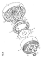
- eine zweite Explosionsdarstellung eines erfindungsgemäßen Kühlerlüfters (schräg von hinten),
- FIG 5
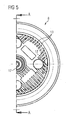
- eine Draufsicht auf ein Gehäuse eines erfindungsgemäßen Kühlerlüfters,
- FIG 6
- eine Schnittdarstellung eines erfindungsgemäßen Kühlerlüfters entlang der Linie AA in
FIG 5 , - FIG 7
- eine Schnittdarstellung eines Ständers und eines Innenläufers gemäß der Erfindung entlang der Linie BB in
FIG 6 , und - FIG 8
- eine Draufsicht auf die Innenseite der Lüfternabe des Lüfterrades des erfindungsgemäßen Kühlerlüfters.
- In
FIG 1 ist ein aus dem Stand der Technik bekannter Kühlerlüfter 101 dargestellt, der einen Lüftermotor 102 mit einem Innenläufer 103 aufweist. Das Aluminiumgehäuse 107, das zugleich als Kühlelement dient, weist ein vorderes Lagerschild 150 und ein hinteres Lagerschild 108 auf, die einen abgeschlossenen Innenraum 151 zur Aufnahme des Ständers 114 und des Innenläufers 103 bilden. In dem hinteren Lagerschild 108 ist die Motorelektronik angeordnet. Sowohl in dem vorderen Lagerschild 150 als auch in dem hinteren Lagerschild 108 sind Lager 117 zur Lagerung einer Antriebswelle 152 vorgesehen. Mit der Antriebswelle 152 verbunden ist der Innenläufer 103 mit Permanentmagneten 126. Der Ständer 114 weist eine Kupfer-Bewicklung 128 auf. An der aus dem vorderen Lagerschild 150 herausragenden Antriebswelle 152 ist die Lüfternabe 105 des Lüfterrades befestigt. Die Übertragung des Drehmomentes von dem Lüftermotor 102 auf das Lüfterrad erfolgt über die Antriebswelle 152. Der Kühlluftstrom 134 verläuft entlang der Motorelektronik, durch die Nutenschlitze 138 des Ständers 114 hindurch und durch Öffnungen in dem vorderen Lagerschild 150 ins Freie. Die axiale Baulänge 116 wird durch die Baulängen von hinterem Lagerschild 108, Ständer 114 bzw. Innenläufer 103, vorderem Lagerschild 150 und Lüfternabe 105 sowie die zugehörigen Zwischenräume bestimmt. - In den
FIG 2 bis 8 ist ein Ausführungsbeispiel der Erfindung abgebildet. Der dargestellte Kühlerlüfter 1 weist einen Lüftermotor 2 mit einem Innenläufer 3 auf. Das Lüfterrad 4 weist eine Lüfternabe 5 und eine Anzahl von sich radial von der Lüfternabe 5 nach außen weg erstreckenden Lüfterblättern 6 auf. Es kann beispielsweise als Axiallüfter ausgebildet sein. - Das als Kühlelement dienende Aluminiumgehäuse 7 besteht im Wesentlichen aus einem hinteren Lagerschild 8, in dem die Motorelektronik 9 mit Bauteilen wie Elektrolytkondensatoren 11, MOSFETs, Prozessor usw., angeordnet ist. Das Lagerschild 8 ist mit einer Vielzahl von Kühlrippen 12 und Durchtrittsöffnungen 13 für Kühlluft versehen. Diese dienen der Wärmeabfuhr durch Wärmeleitung, Wärmestrahlung und Wärmekonvektion.
- Ein Ständer 14 ist an einem Haltering 15 befestigt, der als integraler Bestandteil des Gehäuses 7 ausgebildet ist (vgl.
FIG 7 ) und sich von der Lagerschild 8 in Richtung Lüfterrad 4 erstreckt. In Richtung der Lüfternabe 5 des Lüfterrades 4 ist das Gehäuse 7 offen. Der Ständer 14 und der Innenläufer 3 sind somit ohne ein trennendes Gehäuseteil unmittelbar benachbart zu dem Lüfterrad 4 angeordnet. - Die Lüfternabe 5 ist direkt mit dem Innenläufer 3 verbunden. Die Übertragung des Drehmomentes erfolgt somit direkt von dem Innenläufer 3 auf das Lüfterrad 4. Die axiale Baulänge 16 des Kühlerlüfters 1 ist dadurch gegenüber der in
FIG 1 dargestellten Lösung deutlich verringert. Zugleich sind die Herstellungskosten niedriger als bei herkömmlichen Innenläufer-Lösungen, da weder eine mechanisch hoch belastbare Befestigung des Innenläufers 3 an einer Antriebswelle, noch eine mechanisch hoch belastbare Befestigung des Lüfterrades 4 an der Antriebswelle erforderlich ist. - Die Verbindung der Lüfternäbe 5 mit dem Innenläufer 3 kann auf verschiedene Art und Weise erfolgen, beispielsweise durch Verschrauben, Einspritzen, Aufpressen durch Herstellen einer Preßpassung oder dergleichen.
- In dem hinteren Lagerschild 8 sind zwei zentral angeordnete Kugellager 17 zur Lagerung einer Führungsachse 18 vorgesehen. Der Führungsachse 18 ist keine Antriebsfunktion zugewiesen. Die Führungsachse 18 dient zur Führung des Innenläufers 3 und der Lüfternabe 5. Alternativ dazu kann auch eine andere Lagerkonfiguration verwendet werden, beispielsweise unter Verwendung eines Kugellagers und eines Gleitlagers oder unter Verwendung zweier Gleitlager. Alternativ können die oder das Lager auch in bzw. an dem Innenläufer 3 vorgesehen sein, wobei die Führungsachse 18 dann in dem Gehäuse 7 festgelegt ist. Alternativ können die oder das Lager auch in bzw. an der Lüfternabe 5 vorgesehen sein, wobei die Führungsachse.18 wiederum in dem Gehäuse 7 festgelegt ist.
- Der aus einer Anzahl von Eisenblechen aufgebaute Innenläufer 3 weist ein zentrales Führungselement 19 mit einer Führungsöffnung 21 zur Aufnahme der Führungsachse 18 auf. Das Führungselement 19 ist von einem Zentralbereich 22 umgeben, der offen ausgeführt und zum Durchtritt von Kühlluft geeignet ist. Der Zentralbereich 22 ist in einem Bereich des Innenläufers 3 angeordnet, der magnetisch nicht wirksam ist. Aufgrund des fehlenden Läufermaterials ergibt sich so eine zum Teil erhebliche Gewichtsverringerung des Innenläufers 3 bei gleicher Leistung des Lüftermotors 2.
- Der Zentralbereich 22 ist von einem äußeren Ring 23 umgeben, der das eigentliche "Eisen" des Lüftermotors 2 bildet und mit dem zentralen Führungselement 19 über vier Halte- und Verbindungsstreben 24 verbunden ist. An dem Umfang 25 des äußeren Ringes 23 sind eine Anzahl von Permanentmagneten 26 in Gestalt von Brotlaibmagneten angeordnet derart, dass sich der magnetisch nicht wirksame Bereich im Inneren des Innenläufers 3 ergibt. Alternativ können auch Taschenmagnete verwendet werden. Bei den Permanentmagneten handelt es sich vorzugsweise um Seltenerdenmagnete. Diese sind mit dem äußeren Ring 23 durch eine Kunststoffumspritzung 27 verbunden. Der Ständer 14 weist eine Anzahl von Kupfer-Wicklungen 28 in Form von Einzelzahnbewicklungen auf.
- Die sich topfartig um den Haltering 15 des Gehäuses 7 stülpende Lüfternabe 5 weist an ihrer dem Innenläufer 3 zugewandten Innenseite 29 eine Anzahl von Lüfterblättern 31, 32 auf, die derart angeordnet sind, dass sie bei einer Drehung des Lüfterrades 4 in Drehrichtung 33 Kühlluftströme erzeugen.
- Dabei sind die Lüfterblätter 31, 32 in zwei Gruppen angeordnet. Die eine Gruppe von Lüfterblättern 31 ist nahe der Führungsachse 18 angeordnet und dient vorwiegend zur Erzeugung eines Luftstromes 34 durch den offenen Zentralbereich 22 des Innenläufers 3 und damit vor allem zur Kühlung der in Richtung Lüfterrad 4 offen im Lagerschild 8 angeordneten Motorelektronik 9. Die einzelnen Lüfterblätter 31 bilden dabei einen Radiallüfter. Sie sind entgegen der Drehrichtung 33 (also "rückwärts") gebogen ausgeführt und erstrecken sich ausgehend von der zentralen Führungsöffnung 35 der Lüfternabe 5 in Richtung des Nabenumfangs 36.
- Die andere Gruppe von Lüfterblättern 32 ist von der Führungsachse 18 beabstandet am Nabenumfang 36 und entlang der topfartigen Verlängerung der Lüfternabe 5 angeordnet und dient vorwiegend zur Erzeugung eines Luftstromes 37 durch die Nutenschlitze 38 des Ständers 14. Dieser Kühlluftstrom dient zur direkten Kühlung der Wicklungen 28 des Ständers 14 und darüber hinaus auch zur Kühlung der Motorelektronik 9. Die einzelnen Lüfterblätter 32 sind dabei gerade ausgeführt und erstrecken sich ausgehend von dem Nabenumfang 36 in Drehrichtung 33 schräg nach innen. Um eine ausreichende Kühlung zu ermöglichen, sind die elektromagnetischen Eigenschaften des Lüftermotors 2 derart aufeinander abgestimmt, dass ein niedriger Füllgrad der Nuten vorliegt derart, dass eine für eine Kühlung ausreichender Kühlluftstrom durch die Nutenschlitze 38 hindurch strömen kann.
- Die beiden Gruppen von Lüfterblättern 31, 32 sind voneinander beabstandet. Der Abstand 39 dient zur Aufnahme der Wicklungsenden 41 der Wicklungen 28 des Ständers 14. Damit wird die axiale Baulänge 16 des Kühlerlüfters 1 weiter verringert. Eine besonders hohe Kühlleistung wird wegen der dann erzielbaren höheren Luftgeschwindigkeiten dadurch erreicht, dass die Abstände zwischen den Wicklungen 28 und den angrenzenden Enden der Lüfterblätter 31, 32 sehr gering sind.
- Durch die beiden Kühlluftströme 34, 37 wird eine gegenüber den bekannten Lösungen deutlich verbesserte Kühlung des Ständers 14 und der Motorelektronik 9 mit Hilfe von Wärmekonvektion erzielt. Die Kühlluftverluste sind aufgrund der kürzeren Wege nach außen minimiert. Darüber hinaus verringert sich durch die Erfindung die Anzahl der Bereiche, in denen Turbulenzen entstehen können, so dass sich insgesamt ein deutlich gleichmäßigerer Kühlluftstrom ergibt. Möglich wird dies dadurch, dass zwischen der Lüfternabe 5 mit ihren Lüfterblättern 31, 32 einerseits und den aktiven Motorteilen (Ständer 14 und Innenläufer 3) andererseits keinerlei Zwischenteile vorgesehen sind.
- Die gesamte Motorelektronik 9 ist für eine einfache Montage an der der Lüfternabe 5 zugewandten Vorderseite 42 des Lagerschildes 8 angeordnet. Alternativ dazu kann die Motorelektronik 9 aus thermischen Gründen auch vollständig oder teilweise an der der Lüfternabe 5 abgewandten Rückseite 43 des Lagerschildes 8 angeordnet sein.
Claims (8)
- Kühlerlüfter (1) für ein Kraftfahrzeug, mit einem Lüfterrad (4) und mit einem bürstenlosen Lüftermotor (2) zum Antrieb des Lüfterrades (4),- wobei der Lüftermotor (2) einen Innenläufer (3) aufweist,- wobei das Lüfterrad (4) eine Lüfternabe (5) aufweist und die Lüfternabe (5) direkt mit dem Innenläufer (3) verbunden ist,- wobei die Lüfternabe (5) an ihrer dem Innenläufer (3) zugewandten Innenseite (29) eine Anzahl von Lüfterblättern (31, 32) aufweist,dadurch gekennzeichnet, dass die Lüfterblätter (31, 32) in zwei Gruppen angeordnet sind, wobei die eine Gruppe vorwiegend zur Erzeugung eines Luftstromes (37) durch einen offenen Zentralbereich (22) des Innenläufers (3) dient, während die andere Gruppe vorwiegend zur Erzeugung eines Luftstromes (34) durch die Nutenschlitze (38) des Ständers (14) dient.
- Kühlerlüfter (1) nach Anspruch 1, dadurch gekennzeichnet, dass die beiden Gruppen von Lüfterblättern (31, 32) zur Aufnahme von Wicklungsenden (41) der Wicklungen (28) des Ständers (14) voneinander beabstandet sind.
- Kühlerlüfter (1) nach Anspruch 1 oder 2, dadurch gekennzeichnet, dass die eine Gruppe von Lüfterblättern (31) nahe der Führungsachse (18) angeordnet und die Lüfterblätter (31) entgegen der Drehrichtung (33) gebogen ausgeführt sind.
- Kühlerlüfter (1) nach einem der Ansprüche 1 bis 3, dadurch gekennzeichnet, dass die andere Gruppe von Lüfterblättern (32) am Nabenumfang (36) angeordnet und gerade ausgeführt sind.
- Kühlerlüfter (1) nach einem der Ansprüche 1 bis 4, dadurch gekennzeichnet, dass der Innenläufer (3) eine Führungsöffnung (21) zur Aufnahme der Führungsachse (18) aufweist und die Führungsachse (18) in einem hinteren Lagerschild (8) eines Gehäuses (7) gelagert ist.
- Kühlerlüfter (1) nach einem der Ansprüche 1 bis 4, dadurch gekennzeichnet, dass die Führungsachse (18) in bzw. an dem Innenläufer (3) gelagert und in einem Gehäuse (7) festgelegt ist.
- Kühlerlüfter (1) nach einem der Ansprüche 1 bis 4, dadurch gekennzeichnet, dass die Führungsachse (18) in bzw. an der Lüfternabe (5) gelagert und in einem Gehäuse (7) festgelegt ist.
- Kühlerlüfter (1) nach einem der Ansprüche 5 bis 7, dadurch gekennzeichnet, dass zur Lagerung der Führungsachse (18) zwei Kugellager (17), ein Kugellager und ein Gleitlager oder zwei Gleitlager verwendet werden.
Applications Claiming Priority (2)
| Application Number | Priority Date | Filing Date | Title |
|---|---|---|---|
| DE102005049261A DE102005049261B3 (de) | 2005-10-14 | 2005-10-14 | Kühlerlüfter für ein Kraftfahrzeug |
| PCT/EP2006/066170 WO2007042362A1 (de) | 2005-10-14 | 2006-09-08 | Kühlerlüfter für ein kraftfahrzeug |
Publications (2)
| Publication Number | Publication Date |
|---|---|
| EP1937978A1 EP1937978A1 (de) | 2008-07-02 |
| EP1937978B1 true EP1937978B1 (de) | 2009-11-11 |
Family
ID=37400858
Family Applications (1)
| Application Number | Title | Priority Date | Filing Date |
|---|---|---|---|
| EP06793354A Not-in-force EP1937978B1 (de) | 2005-10-14 | 2006-09-08 | Kühlerlüfter für ein kraftfahrzeug |
Country Status (8)
| Country | Link |
|---|---|
| US (1) | US8016574B2 (de) |
| EP (1) | EP1937978B1 (de) |
| JP (1) | JP2009511806A (de) |
| KR (1) | KR20080066800A (de) |
| CN (1) | CN101317010B (de) |
| AT (1) | ATE448410T1 (de) |
| DE (2) | DE102005049261B3 (de) |
| WO (1) | WO2007042362A1 (de) |
Families Citing this family (46)
| Publication number | Priority date | Publication date | Assignee | Title |
|---|---|---|---|---|
| ITBO20070776A1 (it) * | 2007-11-23 | 2009-05-24 | Spal Automotive Srl | Unita' di ventilazione in particolare per autoveicoli. |
| DE102008042292A1 (de) * | 2008-09-23 | 2010-03-25 | Brose Fahrzeugteile GmbH & Co. Kommanditgesellschaft, Würzburg | Kommutatorlüftermotor |
| DE102008059171B4 (de) * | 2008-11-24 | 2014-08-28 | Brose Fahrzeugteile GmbH & Co. Kommanditgesellschaft, Würzburg | Antriebsmotor mit integrierter Kühlung |
| DE102009003142A1 (de) * | 2009-05-15 | 2010-11-18 | Robert Bosch Gmbh | Lüfter-Rotor-Verbindung für ein Kühlgebläse eines Kraftfahrzeugs |
| EP2457308B1 (de) * | 2009-07-18 | 2014-04-30 | Ebm-Papst St. Georgen GmbH & CO. KG | Lüfter mit einem elektronisch kommutierten antriebsmotor |
| EP2477601B1 (de) * | 2009-09-15 | 2017-09-13 | Union Carbide Chemicals & Plastics Technology LLC | Körperpflegezusammensetzungen mit wässrigen ethylen-acrylsäure-copolymer-dispersionen |
| EP2477600B1 (de) * | 2009-09-15 | 2017-12-20 | Union Carbide Chemicals & Plastics Technology LLC | Silikonersatz für körperpflegezusammensetzungen |
| IT1404252B1 (it) | 2011-01-25 | 2013-11-15 | Gate Srl | Gruppo di ventilazione, particolarmente per uno scambiatore di calore per un autoveicolo |
| IT1404254B1 (it) * | 2011-01-25 | 2013-11-15 | Gate Srl | Ventola, particolarmente per un gruppo di ventilazione per uno scambiatore di calore di un autoveicolo |
| US8760015B2 (en) * | 2011-02-18 | 2014-06-24 | Hamilton Sundstrand Corporation | Cooling of permanent magnet electric machine |
| DE102011115455A1 (de) * | 2011-09-12 | 2013-03-14 | Brose Fahrzeugteile GmbH & Co. Kommanditgesellschaft, Würzburg | Atmender Elektromotor |
| DE102012219771A1 (de) | 2011-12-13 | 2013-06-13 | Brose Fahrzeugteile Gmbh & Co. Kg, Würzburg | Kühlerlüftermodul und Lageranordnung für ein Kühlerlüftermodul |
| FR2989435B1 (fr) * | 2012-04-16 | 2016-01-01 | Valeo Systemes Thermiques | Helice pour ventilateur automobile a raidisseurs de moyeu segmentes |
| ITTO20120765A1 (it) * | 2012-09-05 | 2014-03-06 | Johnson Electric Asti S R L | Gruppo di ventilazione, particolarmente per uno scambiatore di calore di un veicolo |
| US9577493B2 (en) * | 2012-09-20 | 2017-02-21 | Black & Decker Inc. | Motor and electronics cooling system for a high power cordless nailer |
| DE102012024034B4 (de) * | 2012-12-08 | 2025-05-08 | Brose Fahrzeugteile SE & Co. Kommanditgesellschaft, Würzburg | Kühlerlüfter eines Kraftfahrzeugs |
| CN103899551A (zh) * | 2012-12-31 | 2014-07-02 | 杨浩 | 一种电磁内耗型车用风机 |
| US10033242B2 (en) * | 2013-02-01 | 2018-07-24 | Regal Beloit America, Inc. | Electrical machines and methods of assembling the same |
| KR101458811B1 (ko) | 2013-09-09 | 2014-11-07 | 정기영 | 관로의 유속 증폭을 이용한 고속회전체 장치 |
| KR101372521B1 (ko) * | 2013-10-23 | 2014-03-11 | 동양기전 주식회사 | 방열 성능이 향상된 팬 모터 장치 |
| ITTO20140004U1 (it) * | 2014-01-10 | 2015-07-10 | Johnson Electric Asti S R L | Ventola per un elettroventilatore di raffreddamento, particolarmente per uno scambiatore di calore per un autoveicolo |
| DE102014209677A1 (de) * | 2014-05-21 | 2015-11-26 | Robert Bosch Gmbh | Lagerschild für eine elektrische Maschine |
| JP6309389B2 (ja) * | 2014-08-18 | 2018-04-11 | 愛三工業株式会社 | 電動ポンプ |
| US9985494B2 (en) * | 2014-09-08 | 2018-05-29 | Regal Beloit America, Inc. | Electrical machine and controller and methods of assembling the same |
| US9982674B2 (en) | 2014-09-08 | 2018-05-29 | Regal Beloit America, Inc. | Electrical machine and methods of assembling the same |
| US10230290B2 (en) | 2014-09-08 | 2019-03-12 | Regal Beloit America, Inc. | Electrical machine and methods of assembling the same |
| JP6451454B2 (ja) | 2014-09-17 | 2019-01-16 | 日本電産株式会社 | モータ |
| JP2016191310A (ja) * | 2015-03-30 | 2016-11-10 | 日本電産株式会社 | インペラおよび送風機 |
| WO2017170297A1 (ja) * | 2016-03-31 | 2017-10-05 | 日本電産株式会社 | モータ |
| CN106089767A (zh) * | 2016-07-25 | 2016-11-09 | 中车大连机车车辆有限公司 | 机车用大流量轻量化轴流通风机 |
| US11063496B2 (en) * | 2016-08-05 | 2021-07-13 | Nidec Corporation | Vertical motor with resin bracket and cover having circuit board with wireless communication unit |
| US20180102688A1 (en) * | 2016-10-08 | 2018-04-12 | Rakesh K. Dhawan | Universal permanent magnet synchronous motor for high volume low speed fans |
| US11255335B2 (en) * | 2017-11-14 | 2022-02-22 | Regal Beloit America, Inc. | Blower assembly for use in an air handling system and method for assembling the same |
| CN107943136B (zh) * | 2017-11-16 | 2019-09-20 | 中北大学 | 一种基于热传导与热对流的高效无磁温控装置 |
| CN108599451B (zh) * | 2018-06-27 | 2024-01-26 | 沈阳工业大学 | 一种电动汽车用轮毂电机的强化传热结构 |
| CN109441863B (zh) * | 2018-12-26 | 2023-11-28 | 英飞同仁风机股份有限公司 | 一种屋顶离心风机及其电机腔散热的结构及方法 |
| DE102019206422A1 (de) * | 2019-05-03 | 2020-11-05 | Robert Bosch Gmbh | Lüfter |
| IL269253B2 (en) * | 2019-09-10 | 2023-05-01 | U T T Unique Transf Technologies Ltd | A three-phase asynchronous electric machine and a method for its manufacture |
| FR3102317B1 (fr) * | 2019-10-17 | 2022-05-27 | Valeo Equip Electr Moteur | Système électronique d’alimentation d’une machine électrique et ensemble électrique comprenant un tel système électronique |
| US11437900B2 (en) | 2019-12-19 | 2022-09-06 | Black & Decker Inc. | Modular outer-rotor brushless motor for a power tool |
| US11757330B2 (en) | 2019-12-19 | 2023-09-12 | Black & Decker, Inc. | Canned outer-rotor brushless motor for a power tool |
| IT202000002266A1 (it) * | 2020-02-05 | 2021-08-05 | Ferrari Spa | Macchina elettrica rotante con rotore alleggerito |
| CN113803149B (zh) * | 2020-06-17 | 2026-01-09 | 罗伯特·博世有限公司 | 风扇 |
| US12176794B2 (en) | 2021-11-19 | 2024-12-24 | Black & Decker Inc. | Outer-rotor brushless motor for a power tool |
| US20240174074A1 (en) * | 2022-11-29 | 2024-05-30 | Sun Way Shue | Self-Powered Fan Wheel Cooling System for Electric Vehicles |
| DE102024207370A1 (de) * | 2024-08-02 | 2026-02-05 | Brose Fahrzeugteile SE & Co. Kommanditgesellschaft, Würzburg | Elektromotorischer Kühlerlüfter eines Kraftfahrzeugs |
Family Cites Families (33)
| Publication number | Priority date | Publication date | Assignee | Title |
|---|---|---|---|---|
| US3303995A (en) * | 1964-09-08 | 1967-02-14 | Rotron Mfg Co | Fan motor cooling arrangement |
| US3303955A (en) * | 1965-12-01 | 1967-02-14 | Aluminum Co Of America | Container closure |
| FR2373696A1 (fr) * | 1976-12-13 | 1978-07-07 | Ferodo Sa | Ventilateur a moteur refroidi |
| FR2373697A1 (fr) * | 1976-12-13 | 1978-07-07 | Ferodo Sa | Groupe moto-ventilateur a moteur refroidi |
| JPS58193768U (ja) * | 1982-06-14 | 1983-12-23 | 三菱電機株式会社 | 低慣性誘動電動機 |
| DE4143383C2 (de) * | 1991-07-03 | 1995-03-30 | Licentia Gmbh | Axialgebläse, insbesondere zur Kühlung eines dem Kühler eines Fahrzeugs vorgeordneten Kondensators einer Klimaanlage |
| DE4211183A1 (de) | 1992-04-03 | 1993-10-07 | Bosch Gmbh Robert | Umrichter mit Zwischenkreismonitor |
| DE4214160A1 (de) * | 1992-04-30 | 1993-11-04 | Otto Stuckmann | Integrierter luefter |
| DE4215504A1 (de) | 1992-05-12 | 1993-11-18 | Bosch Gmbh Robert | Kommutator-Kleinmotor |
| DE9404147U1 (de) * | 1994-03-11 | 1994-04-28 | Siemens AG, 80333 München | Axiallüfter |
| US5771961A (en) | 1995-08-03 | 1998-06-30 | Valeo Thermique Moteur | Fan module |
| JPH1080191A (ja) | 1996-09-05 | 1998-03-24 | Hitachi Ltd | 可変速電動機駆動システム |
| US5967764A (en) * | 1997-08-08 | 1999-10-19 | Bosch Automotive Systems Corporation | Axial fan with self-cooled motor |
| FR2783647B1 (fr) * | 1998-09-23 | 2000-12-15 | Ecia Equip Composants Ind Auto | Structure de motoventilateur a aimants permanents, notamment pour vehicule automobile |
| IT1308475B1 (it) * | 1999-05-07 | 2001-12-17 | Gate Spa | Motoventilatore, particolarmente per uno scambiatore di calore di unautoveicolo |
| DE10052331A1 (de) * | 2000-10-17 | 2002-05-02 | Stribel Gmbh | Lüfteranlage |
| US6494681B2 (en) * | 2000-12-29 | 2002-12-17 | General Electric Company | Combined axial flow and centrifugal fan in an electrical motor |
| JP4644994B2 (ja) * | 2001-09-07 | 2011-03-09 | 株式会社デンソー | 送風装置 |
| US6655929B2 (en) * | 2001-10-09 | 2003-12-02 | Adda Corporation | Cooling fan dust guard |
| JP3861704B2 (ja) * | 2002-01-31 | 2006-12-20 | 株式会社デンソー | 車両用冷却ファンモータの駆動装置 |
| US6933687B2 (en) | 2002-10-03 | 2005-08-23 | Siemens Vdo Automotive Inc. | Dual motor configuration with primary brushless motor and secondary integrated speed control motor |
| DE10321732B4 (de) | 2003-05-14 | 2013-08-01 | Robert Bosch Gmbh | Kühlung der Ansteuerung von Kühlgebläsen für Kraftfahrzeugmotoren |
| JP2005030363A (ja) | 2003-07-11 | 2005-02-03 | Denso Corp | 車両用電動ファンシステム |
| DE10342049A1 (de) | 2003-09-11 | 2005-05-04 | Siemens Ag | Verfahren und Vorrichtung zur Steuerung eines einen Haupt- und Nebenmotor speisenden Umrichters |
| US7244110B2 (en) * | 2003-09-30 | 2007-07-17 | Valeo Electrical Systems, Inc. | Fan hub assembly for effective motor cooling |
| DE102004058724B4 (de) | 2003-12-09 | 2018-11-15 | Denso Corporation | Wärmetauscher und Kühlmodul mit diesem |
| US7037089B2 (en) * | 2004-05-25 | 2006-05-02 | Hsieh Hsin-Mao | Cooling fan having dual blade sets |
| JP2006007921A (ja) | 2004-06-24 | 2006-01-12 | Denso Corp | 車両用空調装置 |
| JP2006217748A (ja) * | 2005-02-04 | 2006-08-17 | Asmo Co Ltd | ファンモータ |
| DE502005005887D1 (de) * | 2005-05-10 | 2008-12-18 | Siemens Ag | Elektrische Maschine |
| JP2006325315A (ja) * | 2005-05-18 | 2006-11-30 | Asmo Co Ltd | ファンモータ |
| JP2007023964A (ja) * | 2005-07-20 | 2007-02-01 | Denso Corp | 送風装置 |
| JP4291846B2 (ja) * | 2006-11-24 | 2009-07-08 | アスモ株式会社 | ファンモータ |
-
2005
- 2005-10-14 DE DE102005049261A patent/DE102005049261B3/de not_active Expired - Fee Related
-
2006
- 2006-09-08 KR KR1020087011415A patent/KR20080066800A/ko not_active Withdrawn
- 2006-09-08 CN CN2006800380610A patent/CN101317010B/zh not_active Expired - Fee Related
- 2006-09-08 US US12/090,190 patent/US8016574B2/en active Active
- 2006-09-08 JP JP2008534959A patent/JP2009511806A/ja active Pending
- 2006-09-08 EP EP06793354A patent/EP1937978B1/de not_active Not-in-force
- 2006-09-08 AT AT06793354T patent/ATE448410T1/de active
- 2006-09-08 DE DE502006005369T patent/DE502006005369D1/de active Active
- 2006-09-08 WO PCT/EP2006/066170 patent/WO2007042362A1/de not_active Ceased
Also Published As
| Publication number | Publication date |
|---|---|
| EP1937978A1 (de) | 2008-07-02 |
| WO2007042362A1 (de) | 2007-04-19 |
| CN101317010A (zh) | 2008-12-03 |
| JP2009511806A (ja) | 2009-03-19 |
| DE502006005369D1 (de) | 2009-12-24 |
| KR20080066800A (ko) | 2008-07-16 |
| CN101317010B (zh) | 2010-05-19 |
| US8016574B2 (en) | 2011-09-13 |
| DE102005049261B3 (de) | 2007-03-29 |
| US20090142203A1 (en) | 2009-06-04 |
| ATE448410T1 (de) | 2009-11-15 |
Similar Documents
| Publication | Publication Date | Title |
|---|---|---|
| DE102005049261B3 (de) | Kühlerlüfter für ein Kraftfahrzeug | |
| EP1722462B1 (de) | Elektrische Maschine | |
| EP1621773B1 (de) | Kühlgebläse mit Elektromotor | |
| EP2880745B1 (de) | Aktive kühlung eines motors mit integriertem kühlkanal | |
| DE4129411C2 (de) | Fahrzeug-Wechselstromgenerator | |
| EP1446583B1 (de) | Lüfterrad für elektrische maschinen | |
| DE102010044453A1 (de) | Bürstenloser Motor | |
| EP1543244A1 (de) | Anordnung und verfahren zur w rmeabfuhr von einem zu k hlenden bauteil | |
| DE102013200105A1 (de) | Kühlung für Stirnräume einer geschlossenen elektrischen Maschine | |
| EP1387053A1 (de) | Lüfteranordnung zur Kühlung von Kraftfahrzeug-Motoren | |
| DE29700643U1 (de) | Entwärmungskonzept für ein elektrisches Antriebssystem | |
| DE102007031524B4 (de) | Magnet-Generator | |
| DE102016210930A1 (de) | Rotorblechpaket für eine elektrische Maschine | |
| DE19612679C2 (de) | Kühlerventilator für Kraftfahrzeuge | |
| WO2016000930A1 (de) | Elektrischer verdichter für eine verbrennungskraftmaschine | |
| EP1920522B1 (de) | Rotorabdeckung und elektromotor | |
| WO2010145730A1 (de) | Laufzeug für eine fluidenergiemaschine sowie elektrisch angetriebener turbolader | |
| EP1557928A1 (de) | Elektrische Maschine und Verfahren zur Kühlung dieser elektrischen Maschine | |
| DE3101423A1 (de) | Elektrische maschine | |
| DE202007005784U1 (de) | Lüftungseinheit zur Fremdbelüftung eines Elektromotors | |
| DE102005032970B3 (de) | Umrichtermotor | |
| DE102014009315A1 (de) | Verfahren zum Herstellen von verschiedenen Varianten eines Antriebs aus einem Baukasten und Antrieb nach einem solchen Verfahren | |
| EP3474423A1 (de) | Antriebseinrichtung für eine pumpe | |
| DE102011053138A1 (de) | "Elektrischer Außenläufermotor mit Nutkühlung" | |
| DE102017216859A1 (de) | Elektrische Medienspaltmaschine für einen Verdichter und/oder Turbine, Verdichter und/oder Turbine |
Legal Events
| Date | Code | Title | Description |
|---|---|---|---|
| PUAI | Public reference made under article 153(3) epc to a published international application that has entered the european phase |
Free format text: ORIGINAL CODE: 0009012 |
|
| 17P | Request for examination filed |
Effective date: 20080403 |
|
| AK | Designated contracting states |
Kind code of ref document: A1 Designated state(s): AT BE BG CH CY CZ DE DK EE ES FI FR GB GR HU IE IS IT LI LT LU LV MC NL PL PT RO SE SI SK TR |
|
| RAP1 | Party data changed (applicant data changed or rights of an application transferred) |
Owner name: BROSE FAHRZEUGTEILE GMBH & CO. KG |
|
| GRAP | Despatch of communication of intention to grant a patent |
Free format text: ORIGINAL CODE: EPIDOSNIGR1 |
|
| DAX | Request for extension of the european patent (deleted) | ||
| RAP1 | Party data changed (applicant data changed or rights of an application transferred) |
Owner name: BROSE FAHRZEUGTEILE GMBH & CO. KG, WUERZBURG |
|
| RIN1 | Information on inventor provided before grant (corrected) |
Inventor name: REDELBERGER, HARALD Inventor name: DE FILIPPIS, PIETRO |
|
| GRAS | Grant fee paid |
Free format text: ORIGINAL CODE: EPIDOSNIGR3 |
|
| GRAA | (expected) grant |
Free format text: ORIGINAL CODE: 0009210 |
|
| AK | Designated contracting states |
Kind code of ref document: B1 Designated state(s): AT BE BG CH CY CZ DE DK EE ES FI FR GB GR HU IE IS IT LI LT LU LV MC NL PL PT RO SE SI SK TR |
|
| REG | Reference to a national code |
Ref country code: GB Ref legal event code: FG4D Free format text: NOT ENGLISH |
|
| REG | Reference to a national code |
Ref country code: CH Ref legal event code: EP |
|
| REG | Reference to a national code |
Ref country code: IE Ref legal event code: FG4D |
|
| REF | Corresponds to: |
Ref document number: 502006005369 Country of ref document: DE Date of ref document: 20091224 Kind code of ref document: P |
|
| NLV1 | Nl: lapsed or annulled due to failure to fulfill the requirements of art. 29p and 29m of the patents act | ||
| LTIE | Lt: invalidation of european patent or patent extension |
Effective date: 20091111 |
|
| PG25 | Lapsed in a contracting state [announced via postgrant information from national office to epo] |
Ref country code: SE Free format text: LAPSE BECAUSE OF FAILURE TO SUBMIT A TRANSLATION OF THE DESCRIPTION OR TO PAY THE FEE WITHIN THE PRESCRIBED TIME-LIMIT Effective date: 20091111 Ref country code: IS Free format text: LAPSE BECAUSE OF FAILURE TO SUBMIT A TRANSLATION OF THE DESCRIPTION OR TO PAY THE FEE WITHIN THE PRESCRIBED TIME-LIMIT Effective date: 20100311 Ref country code: LT Free format text: LAPSE BECAUSE OF FAILURE TO SUBMIT A TRANSLATION OF THE DESCRIPTION OR TO PAY THE FEE WITHIN THE PRESCRIBED TIME-LIMIT Effective date: 20091111 Ref country code: FI Free format text: LAPSE BECAUSE OF FAILURE TO SUBMIT A TRANSLATION OF THE DESCRIPTION OR TO PAY THE FEE WITHIN THE PRESCRIBED TIME-LIMIT Effective date: 20091111 Ref country code: ES Free format text: LAPSE BECAUSE OF FAILURE TO SUBMIT A TRANSLATION OF THE DESCRIPTION OR TO PAY THE FEE WITHIN THE PRESCRIBED TIME-LIMIT Effective date: 20100222 Ref country code: PT Free format text: LAPSE BECAUSE OF FAILURE TO SUBMIT A TRANSLATION OF THE DESCRIPTION OR TO PAY THE FEE WITHIN THE PRESCRIBED TIME-LIMIT Effective date: 20100311 |
|
| PG25 | Lapsed in a contracting state [announced via postgrant information from national office to epo] |
Ref country code: PL Free format text: LAPSE BECAUSE OF FAILURE TO SUBMIT A TRANSLATION OF THE DESCRIPTION OR TO PAY THE FEE WITHIN THE PRESCRIBED TIME-LIMIT Effective date: 20091111 Ref country code: LV Free format text: LAPSE BECAUSE OF FAILURE TO SUBMIT A TRANSLATION OF THE DESCRIPTION OR TO PAY THE FEE WITHIN THE PRESCRIBED TIME-LIMIT Effective date: 20091111 Ref country code: SI Free format text: LAPSE BECAUSE OF FAILURE TO SUBMIT A TRANSLATION OF THE DESCRIPTION OR TO PAY THE FEE WITHIN THE PRESCRIBED TIME-LIMIT Effective date: 20091111 Ref country code: CY Free format text: LAPSE BECAUSE OF FAILURE TO SUBMIT A TRANSLATION OF THE DESCRIPTION OR TO PAY THE FEE WITHIN THE PRESCRIBED TIME-LIMIT Effective date: 20091111 |
|
| REG | Reference to a national code |
Ref country code: IE Ref legal event code: FD4D |
|
| PG25 | Lapsed in a contracting state [announced via postgrant information from national office to epo] |
Ref country code: BG Free format text: LAPSE BECAUSE OF FAILURE TO SUBMIT A TRANSLATION OF THE DESCRIPTION OR TO PAY THE FEE WITHIN THE PRESCRIBED TIME-LIMIT Effective date: 20100211 Ref country code: DK Free format text: LAPSE BECAUSE OF FAILURE TO SUBMIT A TRANSLATION OF THE DESCRIPTION OR TO PAY THE FEE WITHIN THE PRESCRIBED TIME-LIMIT Effective date: 20091111 Ref country code: IE Free format text: LAPSE BECAUSE OF FAILURE TO SUBMIT A TRANSLATION OF THE DESCRIPTION OR TO PAY THE FEE WITHIN THE PRESCRIBED TIME-LIMIT Effective date: 20091111 Ref country code: EE Free format text: LAPSE BECAUSE OF FAILURE TO SUBMIT A TRANSLATION OF THE DESCRIPTION OR TO PAY THE FEE WITHIN THE PRESCRIBED TIME-LIMIT Effective date: 20091111 Ref country code: RO Free format text: LAPSE BECAUSE OF FAILURE TO SUBMIT A TRANSLATION OF THE DESCRIPTION OR TO PAY THE FEE WITHIN THE PRESCRIBED TIME-LIMIT Effective date: 20091111 |
|
| PG25 | Lapsed in a contracting state [announced via postgrant information from national office to epo] |
Ref country code: SK Free format text: LAPSE BECAUSE OF FAILURE TO SUBMIT A TRANSLATION OF THE DESCRIPTION OR TO PAY THE FEE WITHIN THE PRESCRIBED TIME-LIMIT Effective date: 20091111 Ref country code: CZ Free format text: LAPSE BECAUSE OF FAILURE TO SUBMIT A TRANSLATION OF THE DESCRIPTION OR TO PAY THE FEE WITHIN THE PRESCRIBED TIME-LIMIT Effective date: 20091111 |
|
| PLBE | No opposition filed within time limit |
Free format text: ORIGINAL CODE: 0009261 |
|
| STAA | Information on the status of an ep patent application or granted ep patent |
Free format text: STATUS: NO OPPOSITION FILED WITHIN TIME LIMIT |
|
| 26N | No opposition filed |
Effective date: 20100812 |
|
| PG25 | Lapsed in a contracting state [announced via postgrant information from national office to epo] |
Ref country code: GR Free format text: LAPSE BECAUSE OF FAILURE TO SUBMIT A TRANSLATION OF THE DESCRIPTION OR TO PAY THE FEE WITHIN THE PRESCRIBED TIME-LIMIT Effective date: 20100212 |
|
| BERE | Be: lapsed |
Owner name: BROSE FAHRZEUGTEILE G.M.B.H. & CO. KG, WURZBURG Effective date: 20100930 |
|
| PG25 | Lapsed in a contracting state [announced via postgrant information from national office to epo] |
Ref country code: IT Free format text: LAPSE BECAUSE OF FAILURE TO SUBMIT A TRANSLATION OF THE DESCRIPTION OR TO PAY THE FEE WITHIN THE PRESCRIBED TIME-LIMIT Effective date: 20091111 |
|
| PG25 | Lapsed in a contracting state [announced via postgrant information from national office to epo] |
Ref country code: MC Free format text: LAPSE BECAUSE OF NON-PAYMENT OF DUE FEES Effective date: 20100930 |
|
| REG | Reference to a national code |
Ref country code: CH Ref legal event code: PL |
|
| GBPC | Gb: european patent ceased through non-payment of renewal fee |
Effective date: 20100908 |
|
| PG25 | Lapsed in a contracting state [announced via postgrant information from national office to epo] |
Ref country code: LI Free format text: LAPSE BECAUSE OF NON-PAYMENT OF DUE FEES Effective date: 20100930 Ref country code: CH Free format text: LAPSE BECAUSE OF NON-PAYMENT OF DUE FEES Effective date: 20100930 Ref country code: BE Free format text: LAPSE BECAUSE OF NON-PAYMENT OF DUE FEES Effective date: 20100930 |
|
| PG25 | Lapsed in a contracting state [announced via postgrant information from national office to epo] |
Ref country code: GB Free format text: LAPSE BECAUSE OF NON-PAYMENT OF DUE FEES Effective date: 20100908 |
|
| PG25 | Lapsed in a contracting state [announced via postgrant information from national office to epo] |
Ref country code: LU Free format text: LAPSE BECAUSE OF NON-PAYMENT OF DUE FEES Effective date: 20100908 Ref country code: NL Free format text: LAPSE BECAUSE OF FAILURE TO SUBMIT A TRANSLATION OF THE DESCRIPTION OR TO PAY THE FEE WITHIN THE PRESCRIBED TIME-LIMIT Effective date: 20091111 Ref country code: HU Free format text: LAPSE BECAUSE OF FAILURE TO SUBMIT A TRANSLATION OF THE DESCRIPTION OR TO PAY THE FEE WITHIN THE PRESCRIBED TIME-LIMIT Effective date: 20100512 |
|
| PG25 | Lapsed in a contracting state [announced via postgrant information from national office to epo] |
Ref country code: TR Free format text: LAPSE BECAUSE OF FAILURE TO SUBMIT A TRANSLATION OF THE DESCRIPTION OR TO PAY THE FEE WITHIN THE PRESCRIBED TIME-LIMIT Effective date: 20091111 |
|
| REG | Reference to a national code |
Ref country code: AT Ref legal event code: MM01 Ref document number: 448410 Country of ref document: AT Kind code of ref document: T Effective date: 20110908 |
|
| PG25 | Lapsed in a contracting state [announced via postgrant information from national office to epo] |
Ref country code: AT Free format text: LAPSE BECAUSE OF NON-PAYMENT OF DUE FEES Effective date: 20110908 |
|
| REG | Reference to a national code |
Ref country code: FR Ref legal event code: PLFP Year of fee payment: 11 |
|
| REG | Reference to a national code |
Ref country code: FR Ref legal event code: PLFP Year of fee payment: 12 |
|
| REG | Reference to a national code |
Ref country code: FR Ref legal event code: PLFP Year of fee payment: 13 |
|
| REG | Reference to a national code |
Ref country code: DE Ref legal event code: R082 Ref document number: 502006005369 Country of ref document: DE Representative=s name: ISARPATENT - PATENT- UND RECHTSANWAELTE BEHNIS, DE Ref country code: DE Ref legal event code: R081 Ref document number: 502006005369 Country of ref document: DE Owner name: BROSE FAHRZEUGTEILE SE & CO. KOMMANDITGESELLSC, DE Free format text: FORMER OWNER: BROSE FAHRZEUGTEILE GMBH & CO. KOMMANDITGESELLSCHAFT, WUERZBURG, 97076 WUERZBURG, DE Ref country code: DE Ref legal event code: R082 Ref document number: 502006005369 Country of ref document: DE Representative=s name: ISARPATENT - PATENT- UND RECHTSANWAELTE BARTH , DE |
|
| PGFP | Annual fee paid to national office [announced via postgrant information from national office to epo] |
Ref country code: FR Payment date: 20200812 Year of fee payment: 15 |
|
| PGFP | Annual fee paid to national office [announced via postgrant information from national office to epo] |
Ref country code: DE Payment date: 20200930 Year of fee payment: 15 |
|
| REG | Reference to a national code |
Ref country code: DE Ref legal event code: R119 Ref document number: 502006005369 Country of ref document: DE |
|
| PG25 | Lapsed in a contracting state [announced via postgrant information from national office to epo] |
Ref country code: FR Free format text: LAPSE BECAUSE OF NON-PAYMENT OF DUE FEES Effective date: 20210930 Ref country code: DE Free format text: LAPSE BECAUSE OF NON-PAYMENT OF DUE FEES Effective date: 20220401 |