EP1937859B1 - Verfahren zur kontinuierlichen oder diskontinuierlichen gewinnung eines metalls oder mehrerer metalle aus einer das metall oder eine verbindung des metalls enthaltende schlacke - Google Patents
Verfahren zur kontinuierlichen oder diskontinuierlichen gewinnung eines metalls oder mehrerer metalle aus einer das metall oder eine verbindung des metalls enthaltende schlacke Download PDFInfo
- Publication number
- EP1937859B1 EP1937859B1 EP07819301A EP07819301A EP1937859B1 EP 1937859 B1 EP1937859 B1 EP 1937859B1 EP 07819301 A EP07819301 A EP 07819301A EP 07819301 A EP07819301 A EP 07819301A EP 1937859 B1 EP1937859 B1 EP 1937859B1
- Authority
- EP
- European Patent Office
- Prior art keywords
- metal
- slag
- furnace
- primary
- copper
- Prior art date
- Legal status (The legal status is an assumption and is not a legal conclusion. Google has not performed a legal analysis and makes no representation as to the accuracy of the status listed.)
- Not-in-force
Links
- 239000002893 slag Substances 0.000 title claims abstract description 130
- 229910052751 metal Inorganic materials 0.000 title claims abstract description 58
- 239000002184 metal Substances 0.000 title claims abstract description 58
- 238000000034 method Methods 0.000 title claims abstract description 31
- 150000002739 metals Chemical class 0.000 title claims abstract description 11
- 150000001875 compounds Chemical class 0.000 title claims abstract description 4
- 238000000605 extraction Methods 0.000 title abstract description 3
- 239000010949 copper Substances 0.000 claims abstract description 67
- RYGMFSIKBFXOCR-UHFFFAOYSA-N Copper Chemical compound [Cu] RYGMFSIKBFXOCR-UHFFFAOYSA-N 0.000 claims abstract description 62
- 229910052802 copper Inorganic materials 0.000 claims abstract description 59
- 238000003723 Smelting Methods 0.000 claims abstract description 17
- 239000003638 chemical reducing agent Substances 0.000 claims abstract description 11
- 229910000519 Ferrosilicon Inorganic materials 0.000 claims abstract description 8
- 238000000926 separation method Methods 0.000 claims abstract description 8
- 239000005997 Calcium carbide Substances 0.000 claims abstract description 6
- CLZWAWBPWVRRGI-UHFFFAOYSA-N tert-butyl 2-[2-[2-[2-[bis[2-[(2-methylpropan-2-yl)oxy]-2-oxoethyl]amino]-5-bromophenoxy]ethoxy]-4-methyl-n-[2-[(2-methylpropan-2-yl)oxy]-2-oxoethyl]anilino]acetate Chemical compound CC1=CC=C(N(CC(=O)OC(C)(C)C)CC(=O)OC(C)(C)C)C(OCCOC=2C(=CC=C(Br)C=2)N(CC(=O)OC(C)(C)C)CC(=O)OC(C)(C)C)=C1 CLZWAWBPWVRRGI-UHFFFAOYSA-N 0.000 claims abstract description 6
- XAGFODPZIPBFFR-UHFFFAOYSA-N aluminium Chemical compound [Al] XAGFODPZIPBFFR-UHFFFAOYSA-N 0.000 claims abstract description 5
- 239000007789 gas Substances 0.000 claims abstract description 5
- 229910052782 aluminium Inorganic materials 0.000 claims abstract description 4
- OSMSIOKMMFKNIL-UHFFFAOYSA-N calcium;silicon Chemical compound [Ca]=[Si] OSMSIOKMMFKNIL-UHFFFAOYSA-N 0.000 claims abstract description 4
- 230000009467 reduction Effects 0.000 claims description 43
- OKTJSMMVPCPJKN-UHFFFAOYSA-N Carbon Chemical compound [C] OKTJSMMVPCPJKN-UHFFFAOYSA-N 0.000 claims description 19
- 239000000571 coke Substances 0.000 claims description 19
- 239000000155 melt Substances 0.000 claims description 19
- 230000005291 magnetic effect Effects 0.000 claims description 17
- 238000003756 stirring Methods 0.000 claims description 13
- PXHVJJICTQNCMI-UHFFFAOYSA-N Nickel Chemical compound [Ni] PXHVJJICTQNCMI-UHFFFAOYSA-N 0.000 claims description 11
- 238000011084 recovery Methods 0.000 claims description 10
- BASFCYQUMIYNBI-UHFFFAOYSA-N platinum Chemical compound [Pt] BASFCYQUMIYNBI-UHFFFAOYSA-N 0.000 claims description 9
- 229910052799 carbon Inorganic materials 0.000 claims description 6
- 239000011651 chromium Substances 0.000 claims description 6
- 239000000463 material Substances 0.000 claims description 4
- 229910001092 metal group alloy Inorganic materials 0.000 claims description 4
- 229910052759 nickel Inorganic materials 0.000 claims description 4
- VYZAMTAEIAYCRO-UHFFFAOYSA-N Chromium Chemical compound [Cr] VYZAMTAEIAYCRO-UHFFFAOYSA-N 0.000 claims description 3
- 229910052804 chromium Inorganic materials 0.000 claims description 3
- 229910052697 platinum Inorganic materials 0.000 claims description 3
- JBQYATWDVHIOAR-UHFFFAOYSA-N tellanylidenegermanium Chemical compound [Te]=[Ge] JBQYATWDVHIOAR-UHFFFAOYSA-N 0.000 claims description 3
- 238000010438 heat treatment Methods 0.000 claims description 2
- 239000004411 aluminium Substances 0.000 claims 1
- 239000012768 molten material Substances 0.000 abstract description 2
- 238000002844 melting Methods 0.000 description 22
- 230000008018 melting Effects 0.000 description 22
- XEEYBQQBJWHFJM-UHFFFAOYSA-N Iron Chemical compound [Fe] XEEYBQQBJWHFJM-UHFFFAOYSA-N 0.000 description 15
- 239000004575 stone Substances 0.000 description 15
- SZVJSHCCFOBDDC-UHFFFAOYSA-N iron(II,III) oxide Inorganic materials O=[Fe]O[Fe]O[Fe]=O SZVJSHCCFOBDDC-UHFFFAOYSA-N 0.000 description 14
- 238000010891 electric arc Methods 0.000 description 13
- 229910002804 graphite Inorganic materials 0.000 description 13
- 239000010439 graphite Substances 0.000 description 13
- 239000007788 liquid Substances 0.000 description 12
- 238000004140 cleaning Methods 0.000 description 11
- 239000012141 concentrate Substances 0.000 description 10
- 230000008569 process Effects 0.000 description 8
- UQSXHKLRYXJYBZ-UHFFFAOYSA-N Iron oxide Chemical compound [Fe]=O UQSXHKLRYXJYBZ-UHFFFAOYSA-N 0.000 description 6
- 238000004581 coalescence Methods 0.000 description 6
- 230000008021 deposition Effects 0.000 description 6
- 229910052742 iron Inorganic materials 0.000 description 6
- 230000005012 migration Effects 0.000 description 5
- 238000013508 migration Methods 0.000 description 5
- 239000000203 mixture Substances 0.000 description 5
- 230000015572 biosynthetic process Effects 0.000 description 4
- 238000006243 chemical reaction Methods 0.000 description 4
- 230000005684 electric field Effects 0.000 description 4
- 238000005868 electrolysis reaction Methods 0.000 description 4
- 238000005265 energy consumption Methods 0.000 description 4
- 238000004062 sedimentation Methods 0.000 description 4
- 238000012546 transfer Methods 0.000 description 4
- 238000013019 agitation Methods 0.000 description 3
- QVGXLLKOCUKJST-UHFFFAOYSA-N atomic oxygen Chemical compound [O] QVGXLLKOCUKJST-UHFFFAOYSA-N 0.000 description 3
- 239000003575 carbonaceous material Substances 0.000 description 3
- 238000002347 injection Methods 0.000 description 3
- 239000007924 injection Substances 0.000 description 3
- 230000003993 interaction Effects 0.000 description 3
- 238000004519 manufacturing process Methods 0.000 description 3
- VNWKTOKETHGBQD-UHFFFAOYSA-N methane Chemical compound C VNWKTOKETHGBQD-UHFFFAOYSA-N 0.000 description 3
- 230000003647 oxidation Effects 0.000 description 3
- 238000007254 oxidation reaction Methods 0.000 description 3
- 229910052760 oxygen Inorganic materials 0.000 description 3
- 239000001301 oxygen Substances 0.000 description 3
- 230000000737 periodic effect Effects 0.000 description 3
- 238000012545 processing Methods 0.000 description 3
- UGFAIRIUMAVXCW-UHFFFAOYSA-N Carbon monoxide Chemical compound [O+]#[C-] UGFAIRIUMAVXCW-UHFFFAOYSA-N 0.000 description 2
- QPLDLSVMHZLSFG-UHFFFAOYSA-N Copper oxide Chemical compound [Cu]=O QPLDLSVMHZLSFG-UHFFFAOYSA-N 0.000 description 2
- 239000005751 Copper oxide Substances 0.000 description 2
- 229910015136 FeMn Inorganic materials 0.000 description 2
- 229910002555 FeNi Inorganic materials 0.000 description 2
- 229910000604 Ferrochrome Inorganic materials 0.000 description 2
- 229910002091 carbon monoxide Inorganic materials 0.000 description 2
- 229910000431 copper oxide Inorganic materials 0.000 description 2
- 230000006698 induction Effects 0.000 description 2
- 239000011435 rock Substances 0.000 description 2
- 239000000126 substance Substances 0.000 description 2
- 241001424392 Lucia limbaria Species 0.000 description 1
- 229910004298 SiO 2 Inorganic materials 0.000 description 1
- 229910004283 SiO 4 Inorganic materials 0.000 description 1
- UCKMPCXJQFINFW-UHFFFAOYSA-N Sulphide Chemical compound [S-2] UCKMPCXJQFINFW-UHFFFAOYSA-N 0.000 description 1
- 229910010413 TiO 2 Inorganic materials 0.000 description 1
- 230000009286 beneficial effect Effects 0.000 description 1
- 230000008859 change Effects 0.000 description 1
- 239000003795 chemical substances by application Substances 0.000 description 1
- 238000004891 communication Methods 0.000 description 1
- 239000004020 conductor Substances 0.000 description 1
- 238000010924 continuous production Methods 0.000 description 1
- IYRDVAUFQZOLSB-UHFFFAOYSA-N copper iron Chemical compound [Fe].[Cu] IYRDVAUFQZOLSB-UHFFFAOYSA-N 0.000 description 1
- YOCUPQPZWBBYIX-UHFFFAOYSA-N copper nickel Chemical compound [Ni].[Cu] YOCUPQPZWBBYIX-UHFFFAOYSA-N 0.000 description 1
- 229910000365 copper sulfate Inorganic materials 0.000 description 1
- ARUVKPQLZAKDPS-UHFFFAOYSA-L copper(II) sulfate Chemical compound [Cu+2].[O-][S+2]([O-])([O-])[O-] ARUVKPQLZAKDPS-UHFFFAOYSA-L 0.000 description 1
- 238000005520 cutting process Methods 0.000 description 1
- 230000007423 decrease Effects 0.000 description 1
- 230000000694 effects Effects 0.000 description 1
- 230000002349 favourable effect Effects 0.000 description 1
- 238000005188 flotation Methods 0.000 description 1
- 230000005484 gravity Effects 0.000 description 1
- 238000000227 grinding Methods 0.000 description 1
- 230000006872 improvement Effects 0.000 description 1
- 229910001338 liquidmetal Inorganic materials 0.000 description 1
- 238000010309 melting process Methods 0.000 description 1
- 229910044991 metal oxide Inorganic materials 0.000 description 1
- 150000004706 metal oxides Chemical class 0.000 description 1
- 230000001590 oxidative effect Effects 0.000 description 1
- 238000006213 oxygenation reaction Methods 0.000 description 1
- 239000002245 particle Substances 0.000 description 1
- 238000005191 phase separation Methods 0.000 description 1
- 230000001737 promoting effect Effects 0.000 description 1
- 238000000746 purification Methods 0.000 description 1
- 238000009853 pyrometallurgy Methods 0.000 description 1
- 238000010791 quenching Methods 0.000 description 1
- 230000000171 quenching effect Effects 0.000 description 1
- 238000007670 refining Methods 0.000 description 1
- 239000003340 retarding agent Substances 0.000 description 1
- 239000007787 solid Substances 0.000 description 1
- 238000007711 solidification Methods 0.000 description 1
- 230000008023 solidification Effects 0.000 description 1
- 239000000243 solution Substances 0.000 description 1
- 230000007704 transition Effects 0.000 description 1
Images
Classifications
-
- C—CHEMISTRY; METALLURGY
- C22—METALLURGY; FERROUS OR NON-FERROUS ALLOYS; TREATMENT OF ALLOYS OR NON-FERROUS METALS
- C22B—PRODUCTION AND REFINING OF METALS; PRETREATMENT OF RAW MATERIALS
- C22B7/00—Working up raw materials other than ores, e.g. scrap, to produce non-ferrous metals and compounds thereof; Methods of a general interest or applied to the winning of more than two metals
- C22B7/04—Working-up slag
-
- C—CHEMISTRY; METALLURGY
- C21—METALLURGY OF IRON
- C21D—MODIFYING THE PHYSICAL STRUCTURE OF FERROUS METALS; GENERAL DEVICES FOR HEAT TREATMENT OF FERROUS OR NON-FERROUS METALS OR ALLOYS; MAKING METAL MALLEABLE, e.g. BY DECARBURISATION OR TEMPERING
- C21D5/00—Heat treatments of cast-iron
- C21D5/04—Heat treatments of cast-iron of white cast-iron
-
- C—CHEMISTRY; METALLURGY
- C22—METALLURGY; FERROUS OR NON-FERROUS ALLOYS; TREATMENT OF ALLOYS OR NON-FERROUS METALS
- C22B—PRODUCTION AND REFINING OF METALS; PRETREATMENT OF RAW MATERIALS
- C22B15/00—Obtaining copper
- C22B15/0026—Pyrometallurgy
- C22B15/0054—Slag, slime, speiss, or dross treating
-
- C—CHEMISTRY; METALLURGY
- C22—METALLURGY; FERROUS OR NON-FERROUS ALLOYS; TREATMENT OF ALLOYS OR NON-FERROUS METALS
- C22B—PRODUCTION AND REFINING OF METALS; PRETREATMENT OF RAW MATERIALS
- C22B4/00—Electrothermal treatment of ores or metallurgical products for obtaining metals or alloys
- C22B4/04—Heavy metals
-
- C—CHEMISTRY; METALLURGY
- C22—METALLURGY; FERROUS OR NON-FERROUS ALLOYS; TREATMENT OF ALLOYS OR NON-FERROUS METALS
- C22B—PRODUCTION AND REFINING OF METALS; PRETREATMENT OF RAW MATERIALS
- C22B4/00—Electrothermal treatment of ores or metallurgical products for obtaining metals or alloys
- C22B4/08—Apparatus
-
- C—CHEMISTRY; METALLURGY
- C22—METALLURGY; FERROUS OR NON-FERROUS ALLOYS; TREATMENT OF ALLOYS OR NON-FERROUS METALS
- C22B—PRODUCTION AND REFINING OF METALS; PRETREATMENT OF RAW MATERIALS
- C22B5/00—General methods of reducing to metals
- C22B5/02—Dry methods smelting of sulfides or formation of mattes
- C22B5/04—Dry methods smelting of sulfides or formation of mattes by aluminium, other metals or silicon
-
- C—CHEMISTRY; METALLURGY
- C22—METALLURGY; FERROUS OR NON-FERROUS ALLOYS; TREATMENT OF ALLOYS OR NON-FERROUS METALS
- C22B—PRODUCTION AND REFINING OF METALS; PRETREATMENT OF RAW MATERIALS
- C22B5/00—General methods of reducing to metals
- C22B5/02—Dry methods smelting of sulfides or formation of mattes
- C22B5/18—Reducing step-by-step
-
- C—CHEMISTRY; METALLURGY
- C22—METALLURGY; FERROUS OR NON-FERROUS ALLOYS; TREATMENT OF ALLOYS OR NON-FERROUS METALS
- C22B—PRODUCTION AND REFINING OF METALS; PRETREATMENT OF RAW MATERIALS
- C22B9/00—General processes of refining or remelting of metals; Apparatus for electroslag or arc remelting of metals
- C22B9/16—Remelting metals
- C22B9/18—Electroslag remelting
-
- F—MECHANICAL ENGINEERING; LIGHTING; HEATING; WEAPONS; BLASTING
- F27—FURNACES; KILNS; OVENS; RETORTS
- F27B—FURNACES, KILNS, OVENS OR RETORTS IN GENERAL; OPEN SINTERING OR LIKE APPARATUS
- F27B3/00—Hearth-type furnaces, e.g. of reverberatory type; Electric arc furnaces ; Tank furnaces
- F27B3/04—Hearth-type furnaces, e.g. of reverberatory type; Electric arc furnaces ; Tank furnaces of multiple-hearth type; of multiple-chamber type; Combinations of hearth-type furnaces
- F27B3/045—Multiple chambers, e.g. one of which is used for charging
-
- F—MECHANICAL ENGINEERING; LIGHTING; HEATING; WEAPONS; BLASTING
- F27—FURNACES; KILNS; OVENS; RETORTS
- F27B—FURNACES, KILNS, OVENS OR RETORTS IN GENERAL; OPEN SINTERING OR LIKE APPARATUS
- F27B3/00—Hearth-type furnaces, e.g. of reverberatory type; Electric arc furnaces ; Tank furnaces
- F27B3/08—Hearth-type furnaces, e.g. of reverberatory type; Electric arc furnaces ; Tank furnaces heated electrically, with or without any other source of heat
- F27B3/085—Arc furnaces
-
- F—MECHANICAL ENGINEERING; LIGHTING; HEATING; WEAPONS; BLASTING
- F27—FURNACES; KILNS; OVENS; RETORTS
- F27D—DETAILS OR ACCESSORIES OF FURNACES, KILNS, OVENS OR RETORTS, IN SO FAR AS THEY ARE OF KINDS OCCURRING IN MORE THAN ONE KIND OF FURNACE
- F27D99/00—Subject matter not provided for in other groups of this subclass
- F27D99/0001—Heating elements or systems
- F27D99/0006—Electric heating elements or system
- F27D2099/0021—Arc heating
- F27D2099/0023—DC arc heating
-
- Y—GENERAL TAGGING OF NEW TECHNOLOGICAL DEVELOPMENTS; GENERAL TAGGING OF CROSS-SECTIONAL TECHNOLOGIES SPANNING OVER SEVERAL SECTIONS OF THE IPC; TECHNICAL SUBJECTS COVERED BY FORMER USPC CROSS-REFERENCE ART COLLECTIONS [XRACs] AND DIGESTS
- Y02—TECHNOLOGIES OR APPLICATIONS FOR MITIGATION OR ADAPTATION AGAINST CLIMATE CHANGE
- Y02P—CLIMATE CHANGE MITIGATION TECHNOLOGIES IN THE PRODUCTION OR PROCESSING OF GOODS
- Y02P10/00—Technologies related to metal processing
- Y02P10/20—Recycling
-
- Y—GENERAL TAGGING OF NEW TECHNOLOGICAL DEVELOPMENTS; GENERAL TAGGING OF CROSS-SECTIONAL TECHNOLOGIES SPANNING OVER SEVERAL SECTIONS OF THE IPC; TECHNICAL SUBJECTS COVERED BY FORMER USPC CROSS-REFERENCE ART COLLECTIONS [XRACs] AND DIGESTS
- Y02—TECHNOLOGIES OR APPLICATIONS FOR MITIGATION OR ADAPTATION AGAINST CLIMATE CHANGE
- Y02P—CLIMATE CHANGE MITIGATION TECHNOLOGIES IN THE PRODUCTION OR PROCESSING OF GOODS
- Y02P10/00—Technologies related to metal processing
- Y02P10/25—Process efficiency
Definitions
- the invention relates to a process for the continuous or discontinuous recovery of a metal or metals from a slag containing the metal or a compound of the metal, in which the liquefied metal-containing slag is heated in a primary or secondary smelting unit.
- the melting of copper concentrates produces molten copper and slag.
- the slag contains copper both in dissolved form and in the form of mechanically passed stone inclusions.
- Slag cleaning requires the reduction of magnetite to release the suspended inclusions and allow them to settle and allow for copper oxide coreduction.
- the most commonly used copper slag cleaning in AC arc furnaces requires a relatively large furnace because of the required reduction and sedimentation time, which is 3 to 8 hours. It causes a relatively high specific energy consumption due to the strong specific influence of the heat losses.
- the slag cleaning in an electric arc furnace is carried out as a batchwise or semi-continuous process.
- the flexibility of the arc furnace in the temperature control allows proper slag preheating.
- the formation of dispersed metallic copper inclusions as a product of the reduction of coppery oxide along with a portion of small copper stalagmite confines phase separation and sufficient copper recovery.
- a process for the recovery of metals from metal-containing slags, in particular iron-copper slags in a furnace is known from US 4,110,107 known.
- the molten slag is introduced into an electric arc furnace in which melting takes place.
- a carbon injection unit is used to introduce carbon into the bottom area of the molten bath.
- a slagging agent such as CaO is also introduced into the bath. After reduction, the metal is removed from the oven.
- WO 01/49890 A1 discloses a method for producing blister copper directly from copper sulfate concentrate, in which the copper is obtained from finely ground and cooled copper in a reaction vessel under oxygen enrichment. The oxygenation takes place with supply of oxygen-enriched air, wherein the oxygen content is at least 50%.
- Blister copper also called bladder copper, is unrefined, blistered copper. Copper in the molten state has a higher solubility for gases than the solid metal. During solidification, the gases separate out as small bubbles (blister) in the copper.
- the US 4,060,409 shows a pyrometallurgical system, with which material can be kept in a molten state.
- the system has a vessel for receiving the material, wherein a number of cells of the same size are formed inside the vessel. Furthermore, a plurality of mechanical stirrers are provided to stir the molten material.
- the US 6,436,169 discloses a method of operating a copper smelting furnace wherein an iron-containing substance having greater than 80% by weight of iron having a density between 3.0 and 8.0 is added; The diameter of the particles is between 0.3 and 15 millimeters. The iron-containing substance is added to iron-containing copper slag. Then, a reduction of Fe 3 O 4 to FeO is performed.
- a device for continuous copper smelting is from the EP 0 487 032 B1 known. It has a melting furnace for melting and oxidizing copper concentrate to produce a mixture of stone and slag. Furthermore, a separation furnace for separating the stone from the slag is provided. In a converter furnace, the rock separated from the slag is oxidized to produce blister copper. Melt-retarding agents connect the melting furnace, the separation furnace and the converter furnace. For refining the copper produced in the converter furnace, anode furnaces are provided.
- a connection between the converter furnace and the anode furnaces is provided with crude copper runner.
- a melting furnace, a separation furnace and a converter furnace are provided, which are interconnected via flow connection means. Further, anode furnaces are provided which are in flow communication with the converter furnace.
- the copper concentrate is fed into the smelting furnace where melting and oxidation of the concentrate to produce a mixture of rough and slag occurs.
- the mixture of raw stone and slag is fed to the separation furnace, in which a separation of the raw stone from the slag takes place.
- the blister copper then flows into one of the anode furnaces where the copper is made.
- the invention is therefore based on the object to provide an improved process for the recovery of metals, in particular copper, from slags.
- the solution of this object by the invention is characterized in that the metal-containing slag is heated in a trained as AC electric furnace primary or secondary melting unit and the melt is then transferred from the primary or secondary melting unit in a designed as a DC electric furnace furnace, in an electrolytic deposition of the metal to be recovered takes place, wherein in the primary or secondary melting unit, a reducing agent in the form of Calcium silicide (CaSi), calcium carbide (CaC 2 ), ferrosilicon (FeSi), and / or aluminum (Al) is applied and / or injected.
- a reducing agent in the form of Calcium silicide (CaSi), calcium carbide (CaC 2 ), ferrosilicon (FeSi), and / or aluminum (Al) is applied and / or injected.
- an electric arc furnace is preferably used.
- the metal to be recovered is preferably copper (Cu), which is in a copper-containing slag.
- the metal to be recovered is lead (Pb), zinc (Zn), platinum (Pt), chromium (Cr) or nickel (Ni).
- a pre-reduction or oxidation of the slag or metal concentrates and a deposition of metal or a metal alloy, in particular copper, take place, wherein in the second formed as a DC electric furnace furnace deep slag reduction and removing inclusions occurs.
- an electromagnetic stirring of the melt can also take place.
- at least one electromagnet can act on the melt located in the second furnace.
- at least one permanent magnet acts on the melt located in the second furnace.
- the at least one magnet preferably generates a magnetic field between 50 and 1000 gauss, the magnetic field detecting at least a portion of the cross-section of the melt and the region of the electrodes in the second furnace.
- Coke may also be added as a reducing agent to the primary or secondary melting unit during the heating.
- Carbonaceous material may be applied to the melt surface in the second furnace to form a layer of the carbonaceous material of substantially constant thickness, the layer; acting as an anode, in contact with an electrical connection.
- a layer of metal or metal alloy, in particular copper stone is maintained with a substantially constant thickness, wherein the layer, acting as a cathode, is in contact with an electrical connection ,
- the invention proposes a two-stage slag reduction and the removal of the metal (preferably copper) in two electric arc furnaces, wherein said specific reducing agents are provided which allow a particularly good reduction.
- the first kiln, the three-phase arc furnace serves to pre-reduce the slag and deposit of molten stone, followed by deep slag reduction and entrapment removal in a DC reduction channel furnace with electromagnetic stirring.
- electromagnetic stirring which improves mass transfer to the reduction surface and coalescence of the inclusions, along with slag electrolysis and electrokinetic phenomena, enables effective slag cleaning and high recovery of metal, especially copper.
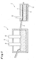
- Fig. 1 is a primary or secondary melting unit 1 to see in the form of an AC furnace, to which a second furnace 2 in the form of a DC furnace connects.
- the melt of copper slag prepared in the furnace 1 is conducted into the second furnace 2 via a connecting means 8 in the form of a melt trough (also possible in the form of a rectangular furnace).
- two electrodes 9 and 10 are immersed in the form of graphite electrodes, which are connected to an AC power source 11.
- the second furnace 2 has a slag inlet 16 for the slag 15 and a slag outlet 17.
- the second furnace 2 there are two electrodes 4 and 5, which are plate-like. Both electrodes 4, 5 are connected via electrical connections in the form of a graphite contact electrode 6 and 7 to a DC power source 12 coupled.
- the upper horizontal electrode 6 is connected to the positive pole of the DC power source 12 and serves as an anode.
- the lower electrode 5, also horizontally arranged is connected to the minus pole of the DC power source 12 and thus serves as a cathode.
- the copper is recovered via an electrolytic process.
- the second furnace 2 is designed as a channel furnace.
- Side electrical coils 13 and 14 are arranged around Metallkeme, which thus form electromagnets 3. With these magnets, an electromagnetic stirring effect is generated, which stirs the melt in the second furnace 2, see below
- An essential feature is that the metal-containing slag is heated in the AC electric furnace 1 and the melt is then transferred from the furnace 1 in the formed as a DC electric furnace furnace 2, in which an electrolytic deposition of the metal to be recovered, z. B. may be present as a sulfide or oxide.
- a reducing agent in the form of calcium silicide (CaSi), calcium carbide (CaC 2 ), ferrosilicon (FeSi), aluminum (Al) and / or reducing gases abandoned or injected.
- the copper content in the molten slag is between 2 and 10% and the magnetite content between 10 and 20% depending on the melting process and the produced stone bag.
- the first step of the slag treatment in the AC electric arc furnace 1 focuses on the magnetite reduction to a value of 7 to 8% and a copper content of 0.8 to 1.2%, which requires a unit energy consumption of 50 to 70 kWh / t, as appropriate original slag composition.
- the above-mentioned degree of slag reduction allows the reduction time to be shortened by about 50%, which corresponds to a twofold increase in the furnace treatment capacities.
- the slag is tapped continuously or at regular intervals to the second DC reduction channel furnace 2 (DC furnace).
- the coke bed 4 on the slag surface, with which the graphite electrode 6 makes contact with the DC power source 12, has the function of the anode and the liquid stone 5 in contact with the graphite block 7 is a cathode in the DC reduction runner 2.
- two permanent magnet blocks are arranged in the window of the furnace vessel, namely at half the height of the slag layer.
- the interaction of a non-uniform, horizontal magnetic field with a non-uniform vertical constant electric field induces the gradient of the Lorentz force acting on the slag.
- the slag speed is 1 to 2 orders of magnitude greater than the natural convection velocities. It causes the slag in the area of the magnet to rotate intensely, which improves the magnetite transition to the coke surface and accelerates the reduction.
- the reactions in the reduction of the magnetite and coreduction of the copper-type oxide are controlled by mass transfer, the agitation of the slag substantially increases the reduction rate.
- agitation of the slag prevents the formation of stagnant liquid and homogenizes the slag.
- Stirring the slag in the first stage of the inclusion removal process is beneficial, thus increasing the likelihood of its collision and coalescence.
- the slag movement increases the likelihood of collision of stone inclusions and metallic copper, thus improving their coalescence and settling.
- the second part of the channel furnace 2 experiences no intensive slag movement and allows a quiet sedimentation of the inclusions.
- the cathodic disassembly of magnetite and the deposition of copper increase the overall rate of magnetite reduction and removal of copper.
- the deposition of CO as anodic product forms further centers of magnetite reduction.
- the rate of migration of the metal or stone inclusions decreases with the drop radius.
- the migration rate is much higher for smaller inclusions than gravity settling.
- Slag processing in crossed electric and magnetic fields uses a number of phenomena that make the slag purification process very intense and effective. Electromagnetic agitation of the slag increases mass transfer, accelerating slag reduction and promoting coalescence of the inclusions. Simultaneous slag electrolysis acts as an additional reducing agent in cathodic reduction of magnetite and copper oxide and anodic formation of carbon monoxide. Electrocapillary migration of the inclusions favors their coalescence and leads to the removal of inclusions from the slag.
- Slag from the melting of concentrate in a flash smelting unit contains 4% Cu and 15% Fe 3 O 4 .
- the slag is tapped every 3 hours and passed through a gutter to the 9.5 MVA three-phase electric arc furnace 1.
- the slag production amount is 30 t / h, this corresponds to a processing of 90 t in each cycle.
- the coke consumption amounts to approx. 8 kg / t and the energy consumption to approx. 70 kWh / t, corresponding to an average power consumption of 6.3 MW.
- the slag begins on the arc furnace for a period of 2 hours.
- the slag with a Cu content of 1.1% and 7% Fe 3 O 4 is transported through the channel 8 into the DC arc furnace 2 with a chamber which is 4 m long and 1 m wide.
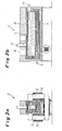
- the reduction channel furnace for semi-continuous slag cleaning is in Fig. 2 shown.
- the slag flows continuously through the reduction channel furnace 2 for 2 hours.
- the average residence time is about 30 minutes.
- the unit power consumption is approximately 35 kWh / t and the required power consumption is 1 MW.
- the current is of the order of 10 kA.
- the estimated coke consumption is about 2 kg / t.
- the finished slag contains 0.5% Cu and 4% magnetite.
- the total energy consumption amounts to 105 kWh / t and the coke consumption to 10 kg / t.
- the method thus operates according to the embodiment as a two-stage copper slag cleaning in electric arc furnaces.
- the graphite or carbon electrodes are introduced into the molten slag and a power supply accomplished via them.
- Coke or other reducing agent is added to the slag surface.
- the control of the slag temperature in the slag cleaning furnace is done by controlling the power consumption.
- a truncation of the recovered metals takes place in the form of copper and metallic copper.
- a periodic or continuous parting of the slag can take place.
- a direct current is applied between the coke layer acting as the anode on the slag surface and the liquid rock functioning as a cathode.
- the superimposed, localized magnetic field generated by electromagnets or permanent magnets is used to move the slag in motion.
- Coke is charged onto the slag surface to keep the layer thickness of the coke layer constant and to maintain favorable electrical contact conditions with the graphite or carbon electrodes.
- a continuous or a periodic parting of the cleaned final slag take place.
- the cutting off of the copper or of the copper is carried out together with metallic copper.
- a matte (copper) layer is maintained on the furnace bottom as a liquid cathode with the catode in contact with a graphite block.
- the electrodes may also consist of another electrically conductive material.
- the copper slag may be the slag obtained by melting copper concentrates into copper stone or directly into blister copper, and the slag obtained by converting copper slug.
- the first electric arc furnace 1 a conventional AC three-phase electric arc furnace or a DC electric arc furnace can be used.
- the induction of a magnetic field generated by permanent magnets or electromagnets is preferably in the range of 50 to 1000 gauss, the permanent magnetic field covering part of the cross-section of the liquid slag in the region of the electrode or electrodes in contact with the coke bed.
- the electrodes used are preferably graphite or carbon electrodes.
- the location of the electrodes causes the current lines to cross the magnetic field lines.
- the optimal positioning of the electrodes causes the streamlines to be perpendicular to the magnetic field lines.
- the layer of liquid metal or metal stone under the slag is in contact with a graphite or other electrode having the function of the cathode; the carbon or coke layer on the slag surface is in contact with a graphite or other electrode having the function of the anode.
- the strength of the direct current is preferably in the range between 500 and 50,000 A, depending on the size of the slag cleaning aggregate, the amount of slag and the temperature.
- Two-stage slag reduction and removal of the copper in two electric arc furnaces enables the first three-phase arc furnace to be used to pre-reduce the slag and deposit copperstone, followed by deep slag reduction and the removal of inclusions in a DC reduction gutter furnace with electromagnetic stirring.
- electromagnetic stirring which improves mass transfer to the reduction surface and coalescence of the inclusions, along with slag electrolysis and electrokinetic phenomena, enables effective slag cleaning and high recovery of copper. It is with the proposed method so - in general - also a reduction of metal oxides possible.
- In the primary smelting unit can also be an oxide melting of concentrates.
Landscapes
- Engineering & Computer Science (AREA)
- Chemical & Material Sciences (AREA)
- Mechanical Engineering (AREA)
- Organic Chemistry (AREA)
- Metallurgy (AREA)
- Materials Engineering (AREA)
- Manufacturing & Machinery (AREA)
- Geology (AREA)
- Life Sciences & Earth Sciences (AREA)
- General Life Sciences & Earth Sciences (AREA)
- Environmental & Geological Engineering (AREA)
- General Engineering & Computer Science (AREA)
- Geochemistry & Mineralogy (AREA)
- Physics & Mathematics (AREA)
- Thermal Sciences (AREA)
- Crystallography & Structural Chemistry (AREA)
- Manufacture And Refinement Of Metals (AREA)
- Conductive Materials (AREA)
Description
- Die Erfindung betrifft ein Verfahren zur kontinuierlichen oder diskontinuierlichen Gewinnung eines Metalls oder mehrerer Metalle aus einer das Metall oder eine Verbindung des Metalls enthaltenden Schlacke, bei dem die verflüssigte metallhaltige Schlacke in einem primären oder sekundären Schmelzaggregat erhitzt wird.
- Beim Erschmelzen von Kupferkonzentraten werden Kupferstein und Schlacke erzeugt. Die Schlacke enthält Kupfer sowohl in gelöster Form als auch in Form von mechanisch übergegangenen Steineinschlüssen. Es gibt zwei wesentliche Verfahren zur Reinigung der Schlacke: Die Schlackeflotation nach dem Abschrecken, Zerkleinern und Mahlen und die pyrometallurgische Reduktion der flüssigen Schlacke.
- Pyrometallurgische Schlackereinigung oder Aufschmelzen von Konzentraten wird zumeist in drei Varianten vorgenommen, nämlich:
- 1) in einem AC-Lichtbogenofen durch Reduktion mit Koks und Elektroden, Schlackevorwärmung und Sedimentation,
- 2) in horizontalen zylindrischen Drehöfen durch Eindüsung eines Reduktionsmittels, z. B. in einem Teniente-Schlackereinigungsofen,
- 3) in vertikalen Konverter mit Eindüsung eines Reduktionsmittels. z. B. TBRC oder IsaSmelt, Aussmelt oder ähnlichen Verfahren.
- Die Schlackereinigung erfordert die Reduktion von Magnetit, um die suspendierten Einschlüsse freizusetzen und ihr Absetzen zu ermöglichen und die Koreduktion von kupferartigem Oxid zuzulassen.
- Die am häufigsten eingesetzte Kupferschlackereinigung in AC-Lichtbogenöfen erfordert einen verhältnismäßig großen Ofen wegen der erforderlichen Reduktions- und Sedimentationszeit, welche 3 bis 8 Stunden beträgt. Sie verursacht einen relativ hohen spezifischen Energieverbrauch aufgrund des starken spezifischen Einflusses der Wärmeverluste. Die Schlackereinigung in einem Lichtbogenofen wird als schubweiser oder halbkontinuierlicher Prozess durchgeführt. Die Flexibilität des Lichtbogenofens bei der Temperaturregelung erlaubt eine richtige Schlackevorwärmung. Die Bildung von dispergierten metallischen Kupfereinschlüssen als Produkt der Reduktion von kupferartigem Oxid zusammen mit einem Teil kleiner Kupfersteineinschlüsse begrenzen jedoch die Phasentrennung und ausreichende Kupferrückgewinnung.
- Ein Verfahren zur Rückgewinnung von Metallen aus metallhaltigen Schlacken, insbesondere von Eisen-Kupfer-Schlacken in einem Schmelzofen ist aus der
US 4,110,107 bekannt. Die geschmolzene Schlacke wird in einen Lichtbogenofen eingebracht, in dem ein Aufschmelzen erfolgt. Eine Kohlenstoff-Einspritzeinheit wird eingesetzt, um Kohlenstoff in den Bodenbereich des Schmelzebades einzubringen. Ein Verschlackungsmittel wie beispielsweise CaO wird ebenfalls in das Bad eingebracht. Nach der Reduktion wird das Metall aus dem Ofen entnommen. - Ein ähnliches Verfahren zum Rückgewinnen insbesondere von Nickel und einer Nickel-Kupfer-Mischung aus einer Schlackenschmelze ist aus der
US 4,036,636 bekannt. Dort wird Magnetit in der Schlacke mit kohlenstoffhaltigen Materialien reduziert. Dabei erfolgt ein Mischen der Schlacke mit einem mechanischen Rührer, während die Reduktion der Schlacke stattfindet. - Aus der
WO 01/49890 A1 - Die
US 4,060,409 zeigt ein pyrometallurgisches System, mit dem Material in geschmolzenem Zustand gehalten werden kann. Das System weist ein Gefäß zur Aufnahme des Materials auf, wobei im Gefäßinneren eine Anzahl von Zellen gleicher Größe ausgebildet ist. Weiterhin ist eine Vielzahl mechanischer Rührer vorgesehen, um das geschmolzene Material rühren zu können. - Die
US 6,436,169 offenbart ein Verfahren zum Betreiben eines Kupfer-Schmelzofens, wobei eine eisenhaltige Substanz mit mehr als 80 Gewichtsprozent Eisen zugegeben wird, die eine Dichte zwischen 3,0 und 8,0 aufweist; der Durchmesser der Partikel liegt dabei zwischen 0,3 und 15 Millimetern. Die eisenhaltige Substanz wird eisenhaltiger Kupferschlacke zugegeben. Dann wird eine Reduktion von Fe3O4 zu FeO durchgeführt. - Auch
US 5,765,489 undWO 2006/131372 A1 offenbaren pyrometallurgische Verfahren zur Metallgewinnung. - Eine Vorrichtung zur kontinuierlichen Kupferverhüttung ist aus der
EP 0 487 032 B1 bekannt. Sie weist einen Schmelzofen zum Schmelzen und Oxidieren von Kupferkonzentrat auf, um ein Gemisch aus Stein und Schlacke zu erzeugen. Weiterhin ist ein Trennofen zum Trennen des Steins von der Schlacke vorgesehen. In einem Konverterofen wird zur Erzeugung von Rohkupfer der von der Schlacke abgetrennte Stein oxidiert. Schmelzeabstichrinnmittel verbinden den Schmelzofen, den Trennofen und den Konverterofen. Zum Raffinieren des in dem Konverterofen erzeugten Kupfers sind Anodenöfen vorgesehen. - Eine Verbindung zwischen dem Konverterofen und den Anodenöfen wird mit Rohkupferrinnmittel geschaffen.
- Aus der
EP 0 487 031 B1 geht ein Verfahren zum kontinuierlichen Schmelzen von Kupfer hervor. Auch hier ist ein Schmelzofen, ein Trennofen und ein Konverterofen vorgesehen, die über Fließverbindungsmittel miteinander verbunden sind. Ferner sind Anodenöfen vorgesehen, die mit dem Konverterofen in Fließverbindung stehen. Das Kupferkonzentrat wird in den Schmelzofen eingespeist, wo ein Schmelzen und Oxidieren des Konzentrates zur Herstellung einer Mischung aus Rohstein und Schlacke erfolgt. Anschließend wird die Mischung aus Rohstein und Schlacke dem Trennofen zugeführt, in dem ein Trennen des Rohsteins von der Schlacke erfolgt. Dann wir der von der Schlacke getrennte Rohstein in den Konverterofen verbracht, wo er zur Herstellung von Rohkupfer oxidiert wird. Das Rohkupfer fließt dann in einen der Anodenöfen, wo das Kupfer hergestellt wird. - Die vorbekannten Verfahren zur Gewinnung eines Metalls aus einer das Metall enthaltenden Schlacke sind bezüglich ihrer Effizienz noch verbesserungsbedürftig.
- Der Erfindung liegt daher die Aufgabe zugrunde, ein verbessertes Verfahren zur Rückgewinnung von Metallen, insbesondere von Kupfer, aus Schlacken bereitzustellen.
- Die Lösung dieser Aufgabe durch die Erfindung ist dadurch gekennzeichnet, dass die metallhaltige Schlacke in einem als Wechselstrom-Elektroofen ausgebildeten primären oder sekundären Schmelzaggregat erhitzt wird und die Schmelze dann von dem primären oder sekundären Schmelzaggregat in einen als Gleichstrom-Elektroofen ausgebildeten Ofen verbracht wird, in dem eine elektrolytische Abscheidung des zu gewinnenden Metalls erfolgt, wobei in das primäre oder sekundäre Schmelzaggregat ein Reduktionsmittel in Form von Calciumsilizid (CaSi), Calciumkarbid (CaC2), Ferrosilicium (FeSi), und/oder Aluminium (Al) aufgegeben und/oder injiziert wird.
- Als primäres oder sekundäres Schmelzaggregat wird bevorzugt ein Lichtbogenofen eingesetzt.
- Das zu gewinnende Metall ist bevorzugt Kupfer (Cu), das sich in einer kupferhaltigen Schlacke befindet. Es ist aber auch möglich, dass es sich bei dem zu gewinnenden Metall um Blei (Pb), Zink (Zn), Platin (Pt), Chrom (Cr) oder Nickel (Ni) handelt.
- In dem als Wechselstrom-Elektroofen ausgebildeten primären oder sekundären Schmelzaggregat kann eine Vorabreduktion oder Oxidation der Schlacke bzw. von Metallkonzentraten und ein Abscheiden von Metallstein oder einer Metalllegierung, insbesondere von Kupferstein, erfolgen, wobei in dem zweiten als Gleichstrom-Elektroofen ausgebildeten Ofen eine tiefgehende Schlackenreduktion und ein Entfernen von Einschlüssen erfolgt.
- In dem zweiten als Gleichstrom-Elektroofen ausgebildeten Ofen kann während der Gewinnung des Metalls auch ein elektromagnetisches Rühren der Schmelze erfolgen. Zur Erzeugung des elektromagnetischen Rührens kann mindestens ein Elektromagnet auf die sich im zweiten Ofen befindliche Schmelze wirken. Es kann aber auch vorgesehen werden, dass zur Erzeugung des elektromagnetischen Rührens mindestens ein Dauermagnet auf die sich im zweiten Ofen befindliche Schmelze wirkt. Der mindestens eine Magnet erzeugt bevorzugt ein Magnetfeld zwischen 50 und 1.000 Gauss, wobei das Magnetfeld zumindest einen Teil des Querschnittes der Schmelze und des Bereichs der Elektroden in dem zweiten Ofen erfasst.
- In das primäre oder sekundäre Schmelzaggregat kann während des Erhitzens weiterhin als Reduktionsmittel auch Koks zugegeben werden.
- Auf die Schmelzeoberfläche in dem zweiten Ofen kann kohlenstoffhaltiges Material, insbesondere Koks, so aufgegeben werden, dass sich eine Schicht des kohlenstoffhaltiges Materials mit im wesentlichen konstanter Dicke ausbildet, wobei die Schicht; als Anode wirkend, mit einer elektrischen Verbindung in Kontakt steht. Ferner kann vorgesehen werden, dass im Bodenbereich unter der Schmelze in dem zweiten Ofen eine Schicht aus Metallstein bzw. Metalllegierung, insbesondere aus Kupferstein, mit im wesentlichen konstanter Dicke aufrechterhalten wird, wobei die Schicht, als Kathode wirkend, mit einer elektrischen Verbindung in Kontakt steht.
- Die Erfindung schlägt also eine zweistufige Schlackereduktion und die Entfernung des Metalls (vorzugsweise des Kupfers) in zwei Lichtbogenöfen vor, wobei die genannten spezifischen Reduktionsmittel vorgesehen werden, die eine besonders gute Reduktion erlauben. Der erste Ofen, der Drehstrom-Lichtbogenofen, dient der Vorabreduktion der Schlacke und der Abscheidung von Metallstein (Kupferstein), gefolgt von einer tiefgehenden Schlackereduktion und Entfernung von Einschlüssen in einem DC-Reduktions-Rinnenofen mit elektromagnetischem Rühren. Der Einsatz von elektromagnetischem Rühren, welches den Stoffübergang auf die Reduktionsfläche und die Koaleszenz der Einschlüsse verbessert, gemeinsam mit Schlackeelektrolyse und elektrokinetischen Phänomenen ermöglichen eine wirksame Schlackereinigung und hohe Rückgewinnung von Metall, insbesondere Kupfer.
- In den Zeichnungen ist ein Ausführungsbeispiel der Erfindung dargestellt. Es zeigen:
- Fig. 1
- eine schematische Darstellung eines primären bzw. sekundären Schmelzaggregats in Form eines Drehstrom-Lichtbogenofens und eines nachgeschalteten DC-Reduktions-Rinnenofens und
- Fig. 2a
- und
- Fig. 2b
- die geschnittene Vorderansicht und die geschnittene Seitenansicht des DC-Reduktions-Rinnenofens zur tiefgehenden Schlackeredukti- on und Entfernung von Einschlüssen unter Verwendung eines Koks- betts und flüssigem Kupferstein als Elektroden.
- In
Fig. 1 ist ein primäres oder sekundäres Schmelzaggregat 1 in Form eines Wechselstromofens zu sehen, an den sich ein zweiter Ofen 2 in Form eines Gleichstromofens anschließt. Die im Ofen 1 vorbereitete Schmelze aus Kupferschlacke wird über ein Verbindungsmittel 8 in Form einer Schmelzerinne (auch möglich in Form eines Rechteckofens) in den zweiten Ofen 2 geleitet. - In den ersten Ofen 1 und namentlich in die sich in diesem Ofen befindliche Schlackenschmelze tauchen zwei Elektroden 9 und 10 in Form von GraphitElektroden ein, die an eine Wechselstromquelle 11 angeschlossen sind.
- Die Schlacken enthalten je nach Art des primären und/oder sekundären Schmelzaggregats 1
- Metalltröpfchen wie beispielsweise bei Ferrolegierungsprozessen (z. B. FeNi, FeMn, FeCr, FeNb und TiO2-Herstellungsprozessen),
- Metalle in sulfidischer oder oxidischer Form, wobei IsaSmelt, Aussmelt, Outokumpu oder TBRC als Primärschmelzer fungieren,
- Metalle und Metalllegierungen, die bei der Verarbeitung von oxidischen Einsatzmaterialien, z. B. aus einem Elektroofen oder Schachtofen, als Produkte entstehen.
- Der zweite Ofen 2 hat einen Schlackeneintritt 16 für die Schlacke 15 sowie einen Schlackenaustritt 17. Im zweiten Ofen 2 befinden sich zwei Elektroden 4 und 5, die plattenartig ausgebildet sind. Beide Elektroden 4, 5 sind über elektrische Verbindungen in Form einer Graphit-Kontaktelektrode 6 bzw. 7 an eine Gleichstromquelle 12 gekoppelt. Die obere horizontal liegende Elektrode 6 ist an den Plus-Pol der Gleichstromquelle 12 angeschlossen und dient als Anode. Entsprechend ist die untere ebenfalls horizontal angeordnete Elektrode 5 an den Minus-Pol der Gleichstromquelle 12 angeschlossen und dient damit als Kathode. Über einen elektrolytischen Prozess wird das Kupfer gewonnen.
- Wie
Fig. 2 entnommen werden kann, ist der zweite Ofen 2 als Rinnenofen ausgebildet. Seitlich sind elektrische Spulen 13 und 14 um Metallkeme angeordnet, die damit Elektromagnete 3 bilden. Mit diesen Magneten wird ein elektromagnetischer Rühreffekt erzeugt, die die Schmelze im zweiten Ofen 2 rührt, s. u. - Wesentliches Merkmal ist, dass die metallhaltige Schlacke im Wechselstrom-Elektroofen 1 erhitzt wird und die Schmelze dann vom Ofen 1 in den als Gleichstrom-Elektroofen ausgebildeten Ofen 2 verbracht wird, in dem eine elektrolytische Abscheidung des zu gewinnenden Metalls erfolgt, das z. B. als Sulfid oder Oxid vorliegen kann. Dabei wird in den Ofen 1 ein Reduktionsmittel in Form von Calciumsilizid (CaSi), Calciumkarbid (CaC2), Ferrosilicium (FeSi), Aluminium (Al) und/oder Reduktionsgasen aufgegeben bzw. injiziert.
- Bei der Reduktion findet ein an sich bekannter Prozess statt, der - am nicht erfindungsgemäßen Beispiel der Zugabe von Koks - wie folgt aussieht: Magnetit und kupferartiges Oxid in der Schlacke reagieren hier mit dem Kohlenstoff der Graphitelektroden 9, 10 und zugegebenen Koks gemäß der Gleichungen:
Fe3O4 + CO = 3 FeO + CO2
Cu2O + CO = 2 Cu + CO2
CO2 + C = 2 CO
- Die Reduktion von kupferartigem Oxid wird durch die Magnetitkoreduktion eingeschränkt. Die Bedingungen der Koreduktion werden durch das Gleichgewicht dieser Reaktion bestimmt:
(Cu2O)Schlacke + 3 (FeO)Schlacke ⇔ 2 (CU)Metall + (Fe3O4)Schlacke
- Der Kupfergehalt in der Schmelzenschlacke liegt zwischen 2 und 10 % und der Magnetitgehalt zwischen 10 und 20 % je nach Schmelzverfahren und der erzeugten Steingüte.
- Der erste Schritt der Schlackebehandlung im AC-Lichtbogenofen 1 konzentriert sich auf die Magnetitreduktion auf einen Wert von 7 bis 8 % und einen Kupfergehalt von 0,8 bis 1,2 %, was einen Einheitsenergieverbrauch von 50 bis 70 kWh/t erfordert, je nach ursprünglicher Schlackezusammensetzung. Der oben genannte Grad der Schlackereduktion erlaubt die Reduktionszeit um ca. 50 % zu kürzen, was einer zweifachen Erhöhung der Ofenbehandlungskapazitäten entspricht. Die Schlacke wird kontinuierlich oder in regelmäßigen Abständen zum zweiten DC-Reduktions-Rinnenofen 2 (Gleichstromofen) abgestochen.
- Das Koksbett 4 auf der Schlackeoberfläche, mit dem die Graphitelektrode 6 den Kontakt zur Gleichstromquelle 12 herstellt, hat die Funktion der Anode und der flüssige Stein 5 in Kontakt mit dem Graphitblock 7 ist eine Kathode im DC-Reduktions-Rinnenofen 2.
- Einlassseitig im Ofen sind zwei Permanentmagnetblöcke im Fenster des Ofengefäßes angeordnet und zwar auf halber Höhe der Schlackeschicht. Das Zusammenwirken eines nicht gleichförmigen, horizontalen magnetischen Felds mit einem nicht gleichförmigen vertikalen konstanten elektrischen Feld induziert den Gradienten der auf die Schlacke wirkenden Lorentzkraft.
- Die Lorentz-Kraft, die in jedem elementaren Volumen leitfähiger Flüssigkeit, wie z. B. flüssiger Schlacke, in gekreuzten konstanten elektrischen und permanenten magnetischen Feldern wirkt, verändert offensichtlich die relative Dichte der Flüssigkeit:

- γA -
- scheinbare relative Dichte in N m-3,
- γ -
- relative Dichte in N m-3,
- j -
- Stromdichte in einer Flüssigkeit in A m-2,
- B -
- magnetische Induktion in T.
- Mit oben genannter Kraft bei einer Stromdichte von 200 bis 2000 A/m2 und einer magnetischen Feldstärke von 0,005 bis 0.1 Tesla ist die Schlackegeschwindigkeit 1 bis 2 Größenordnungen größer im Vergleich zu den natürlichen Konvektionsgeschwindigkeiten. Sie versetzt die Schlacke im Bereich des Magnets in intensive Rotation, wodurch der Magnetitübergang auf die Koksoberfläche verbessert und die Reduktion beschleunigt wird. Bei der hohen Temperatur der Schlackereduktion (1200 bis 1300 °C) werden die Reaktionen bei der Reduktion des Magnetits und Koreduktion des kupferartigen Oxids durch Stoffübergang gesteuert, das Rühren der Schlacke erhöht die Reduktionsgeschwindigkeit wesentlich.
- Darüber hinaus verhindert das Rühren der Schlacke die Bildung von stagnierender Flüssigkeit und homogenisiert die Schlacke. Das Rühren der Schlacke in der ersten Stufe des Verfahrens für die Entfernung von Einschlüssen ist günstig, womit die Wahrscheinlichkeit ihrer Kollision und ihrer Koaleszenz erhöht wird.
- Die Schlackebewegung erhöht die Wahrscheinlichkeit der Kollision von Steineinschlüssen und metallischem Kupfer, womit deren Koaleszenz und Absetzen verbessert wird. Der zweite Teil des Rinnenofens 2 erfährt keine intensive Schlackebewegung und erlaubt eine ruhige Sedimentation der Einschlüsse.
- Aufgrund der Ionenstruktur der flüssigen Schlacke regt der Gleichstrom die Schlackeelektrolyse an. Kathodische Reduktion und anodische Oxidation resultieren in der Magnetitreduktion, Kupferabscheidung und Bildung von Kohlenmonoxid auf den Elektroden entsprechend den Reaktionen:
Kathode: Fe3+ + e = Fe2+ Cu+ + e = Cu° Anode: SiO4 4- + 2 C = SiO2 + 2[CO] + 4 e O2- + C = [CO] + 2 e - Die kathodische Zerlegung von Magnetit und die Abscheidung von Kupfer erhöhen die gesamte Geschwindigkeit der Magnetitreduktion und Entfernung von Kupfer. Die Abscheidung von CO als anodisches Produkt bildet weitere Zentren der Magnetitreduktion.
- Die zusätzliche auf metallische Einschlusse wirkende Kraft als Ergebnis der scheinbaren Änderung der relativen Dichte der Schlacke und die Interaktion des Stroms im Metall und des Magnetfelds sind gleich:

- FEBF -
- Auftriebskraft in N,
- j -
- Stromdichte in A/m2 ,
- B -
- Induktivität magnetisches Feld in T,
- r -
- Radius des Einschlusses in m.
- Die Interaktion des elektrischen Felds mit der elektrischen Oberflächenladung auf der Einschlussoberfläche lässt den Metalltropfen entlang der elektrischen Feldlinien wandern; die Wanderungsgeschwindigkeit, bekannt als Phänomen der Elektrokapillaritätsbewegung, wird durch die Formel von Levich beschrieben:

- vEM -
- Wanderungsgeschwindigkeit in m s-1,
- ε -
- Oberflächenladung in coul m-2,
- E -
- Stärke des elektrischen Felds in V m-1,
- ηS -
- Schlackeviskosität in Pa s,
- κ -
- Spezifische Leitfähigkeit der Schlacke in Ω-1 m-1,
- w -
- Widerstand der Metall/Schlackegrenzfläche in Ω m2.
- Basierend auf der elektrischen Ladungsdichte nimmt die Wanderungsgeschwindigkeit des Metalls oder der Steineinschlüsse gemäß der oben aufgeführten Formel mit dem Tropfenradius ab. Die Wanderungsgeschwindigkeit ist bei kleineren Einschlüssen wesentlich höher als das Absetzen durch Schwerkraft.
- Die Schlackeverarbeitung in gekreuzten elektrischen und magnetischen Feldern nutzt eine Reihe von Phänomenen, durch die der Schlackereinigungsprozess sehr intensiv und effektiv wird. Elektromagnetisches Rühren der Schlacke erhöht den Stoffübergang, wodurch die Schlackereduktion beschleunigt und die Koaleszenz der Einschlüsse gefördert wird. Gleichzeitige Schlackeelektrolyse wirkt bei kathodischer Reduktion von Magnetit und Kupferoxid und anodischer Bildung von Kohlenmonoxid als zusätzliches Reduktionsmittel. Elektrokapillare Wanderung der Einschlüsse begünstigt deren Koaleszenz und führt zur Entfernung von Einschlüssen aus der Schlacke.
- Schlacke aus dem Erschmelzen von Konzentrat in einem Flash-Schmelzaggregat enthält 4% Cu und 15% Fe3O4. Die Schlacke wird alle 3 Stunden abgestochen und durch eine Rinne an den 9,5 MVA-Drehstrom-Lichtbogenofen 1 übergeben. Die Schlackeproduktionsmenge beträgt 30 t/h, dies entspricht einer Verarbeitung von 90 t in jedem Zyklus. Der Koksverbrauch beläuft sich auf ca.8 kg/t und der Energieverbrauch auf ungefähr 70 kWh/t, entsprechend einer durchschnittlichen Leistungsaufnahme von 6,3 MW. Nach einer Stunde beginnt der Schlackeabstich auf dem Lichtbogenofen über einen Zeitraum von 2 Stunden. Die Schlacke mit einem Cu-Gehalt von 1,1 % und 7 % Fe3O4 wird durch die Rinne 8 in den DC-Lichtbogenofen 2 mit einer Kammer transportiert, welche 4 m lang und 1 m breit ist. Der Reduktions-Rinnenofen zur halbkontinuierlichen Schlackereinigung ist in
Fig. 2 dargestellt. Die Schlacke fließt 2 Stunden kontinuierlich durch den Reduktions-Rinnenofen 2. Bei einem Schlackespiegel von 1 m beträgt die durchschnittliche Verweilzeit ungefähr 30 Minuten. Bei Ofenwärmeverlusten von 1 GJ/h beträgt der Einheitsstromverbrauch ungefähr 35 kWh/t und die erforderliche Leistungsaufnahme 1 MW. Bei einer geschätzten Spannung von 100 V liegt die Stromstärke in der Größenordnung von 10 kA. Der geschätzte Koksverbrauch ist ca. 2 kg/t. Die Fertigschlacke enthält 0,5% Cu und 4% Magnetit. Der gesamte Energieverbrauch beläuft sich auf 105 kWh/t und der Koksverbrauch auf 10 kg/t. - Das Verfahren arbeitet gemäß dem Ausführungsbeispiel also als zweistufige Kupferschlackenreinigung in Lichtbogenöfen.
- Es kann ein periodisches oder ein kontinuierliches Chargieren der Schlacke in den ersten Lichtbogenofen 1 erfolgen. In diesen Ofen 1 werden die Graphit- bzw. Kohlenstoffelektroden in die geschmolzene Schlacke eingeführt und über sie eine Stromzufuhr bewerkstelligt. Auf die Schlackenoberfläche wird Koks oder ein anderes Reduktionsmittel zugegeben. Die Regelung der Schlackentemperatur im Schlackenreinigungsofen erfolgt durch Regelung der Leistungsaufnahme. Schließlich erfolgt ein Abstechen der gewonnenen Metalle in Form von Kupferstein und metallischem Kupfer.
- Auch im DC-Rinnenofen 2 kann ein periodisches oder kontinuierliches Abstechen der Schlacke erfolgen. Ein Gleichstrom wird zwischen der als Anode fungierenden Koksschicht an der Schlackenoberfläche und der als Kathode fungierenden flüssigen Stein angelegt. Das überlagerte, örtlich begrenzte Magnetfeld, das durch Elektromagnete oder Dauermagnete erzeugt wird, wird benutzt, um die Schlacke in Bewegung zu versetzen. Auf die Schlackenoberfläche wird Koks chargiert, um die Schichtdicke der Koksschicht konstant zu halten und um günstige elektrische Kontaktbedingungen mit den Graphit- oder Kohlenstoffelektroden aufrecht zu erhalten. Auch hier kann ein kontinuierliches oder ein periodisches Abstechen der gereinigten Fertigschlacke erfolgen. Gleichermaßen kann periodisch das Abstechen des Kupfersteins oder des Kupfersteins zusammen mit metallischem Kupfer erfolgen. Weiterhin wird eine Kupferstein-(Kupfer-)Schicht auf dem Ofenboden als flüssige Kathode aufrechterhalten, wobei die Katzode in Kontakt mit einem Graphitblock steht. Die Elektroden können auch aus einem anderen elektrisch leitendem Material bestehen.
- Die Kupferschlacke kann diejenige Schlacke darstellen, die durch das Erschmelzen von Kupferkonzentraten zu Kupferstein oder unmittelbar zu Blisterkupfer gewonnen wird, sowie diejenige Schlacke, die durch das Umwandeln von Kupferstein gewonnen wird.
- Als erster Lichtbogenofen 1 kann ein klassischer AC-Drehstrom-Lichtbogenofen oder ein DC-Lichtbogenofen eingesetzt werden.
- Die Induktion eines durch Permanentmagneten oder Elektromagneten erzeugten Magnetfelds liegt bevorzugt im Bereich von 50 bis 1.000 Gauss, wobei das permanente magnetische Feld einen Teil des Querschnitts der Flüssigschlacke im Bereich der Elektrode oder Elektroden in Kontakt mit dem Koksbett abdecken.
- Als Elektroden werden bevorzugt Graphit- oder Kohlenstoffelektroden eingesetzt. Der Ort der Elektroden lässt die Stromlinien die magnetischen Feldlinien kreuzen. Die optimale Positionierung der Elektroden führt dazu, dass die Stromlinien senkrecht zu den magnetischen Feldlinien verlaufen.
- Wie erläutert, ist die Schicht des flüssigen Metalls bzw. der Metallstein unter der Schlacke in Kontakt mit einer Graphit- oder anderen Elektrode, die die Funktion der Kathode hat; der Kohlenstoff bzw. die Koksschicht an der Schlackeoberfläche ist in Kontakt mit einer Graphit- oder anderen Elektrode, die die Funktion der Anode hat.
- Die Stärke des Gleichstroms liegt bevorzugt im Bereich zwischen 500 und 50.000 A, abhängig von der Größe des Schlackereinigungsaggregats, der Schlackemenge und der Temperatur.
- Wengleich das vorgeschlagene Verfahren bevorzugt für die Gewinnung von Kupfer vorgesehen ist, kann es auch für andere Metalle wie für Blei (Pb), Zink (Zn), Platin (Pt), Chrom (Cr) oder Nickel (Ni) angewendet werden.
- Durch die zweistufige Schlackereduktion und die Entfernung des Kupfers in zwei Lichtbogenöfen wird erreicht, dass der erste Drehstrom-Lichtbogenöfen zur Vorabreduktion der Schlacke und Abscheidung von Kupferstein eingesetzt werden kann, gefolgt von einer tiefgehenden Schlackereduktion und der Entfernung von Einschlüssen in einem DC-Reduktions-Rinnenofen mit elektromagnetischem Rühren. Der Einsatz von elektromagnetischem Rühren, welches den Stoffübergang auf die Reduktionsfläche und die Koaleszenz der Einschlüsse verbessert, gemeinsam mit Schlackeelektrolyse und elektrokinetischen Phänomenen ermöglichen eine wirksame Schlackereinigung und eine hohe Rückgewinnung von Kupfer. Es wird mit dem vorgeschlagenen Verfahren also - allgemein gesagt - auch eine Reduktion von Metalloxiden möglich. Im Primärenschmelzaggregat kann auch ein oxidisches Aufschmelzen von Konzentraten erfolgen.
-
- 1
- primäres oder sekundäres Schmelzaggregat (Wechselstromofen)
- 2
- zweiter Ofen (Gleichstromofen)
- 3
- Elektromagnet
- 4
- Elektrode (Anode)
- 5
- Elektrode (Kathode)
- 6
- elektrische Verbindung (Graphitelektrode)
- 7
- elektrische Verbindung (Graphitelektrode)
- 8
- Verbindungsmittel
- 9
- Elektrode
- 10
- Elektrode
- 11
- Wechselstromquelle
- 12
- Gleichstromquelle
- 13
- elektrische Spule
- 14
- elektrische Spule
- 15
- Schlacke
- 16
- Schlackeneintritt
- 17
- Schlackenaustritt
Claims (12)
- Verfahren zur kontinuierlichen oder diskontinuierlichen Gewinnung eines Metalls oder mehrerer Metalle aus einer das Metall oder eine Verbindung des Metalls enthaltenden Schlacke, bei dem die verflüssigte metallhaltige Schlacke in einem primären oder sekundären Schmelzaggregat (1) erhitzt wird,
dadurch gekennzeichnet,
dass die metallhaltige Schlacke in einem als Wechselstrom-Elektroofen ausgebildeten primären oder sekundären Schmelzaggregat (1) erhitzt wird und die Schmelze dann von dem primären oder sekundären Schmelzaggregat (1) in einen als Gleichstrom-Elektroofen ausgebildeten Ofen (2) verbracht wird, in dem eine elektrolytische Abscheidung des zu gewinnenden Metalls erfolgt, wobei in das primäre oder sekundäre Schmelzaggregat (1) ein Reduktionsmittel in Form von Calciumsilizid (CaSi), Calciumkarbid (CaC2), Ferrosilicium (FeSi) und/oder Aluminium (Al) aufgegeben und/oder injiziert wird. - Verfahren nach Anspruch 1, dadurch gekennzeichnet, dass als primäres oder sekundäres Schmelzaggregat (1) ein Lichtbogenofen eingesetzt wird.
- Verfahren nach Anspruch 1 oder 2, dadurch gekennzeichnet, dass das zu gewinnende Metall Kupfer (Cu) ist, das sich in einer kupferhaltigen Schlacke befindet.
- Verfahren nach Anspruch 1 oder 2, dadurch gekennzeichnet, dass das zu gewinnende Metall Blei (Pb), Zink (Zn), Platin (Pt), Chrom (Cr) oder Nickel (Ni) ist, das sich in einer Schlacke befindet.
- Verfahren nach einem der Ansprüche 1 bis 4, dadurch gekennzeichnet, dass in dem als Wechselstrom-Elektroofen ausgebildeten primären oder sekundären Schmelzaggregat (1) eine Vorabreduktion der Schlacke und ein Abscheiden von Metallstein oder einer Metalllegierung, insbesondere von Kupferstein, erfolgt und dass in dem zweiten als Gleichstrom-Elektroofen ausgebildeten Ofen (2) eine tiefgehende Schlackenreduktion und ein Entfernen von Einschlüssen erfolgt.
- Verfahren nach einem der Ansprüche 1 bis 5, dadurch gekennzeichnet, dass in dem zweiten als Gleichstrom-Elektroofen ausgebildeten Ofen (2) während der Gewinnung des Metalls ein elektromagnetisches Rühren der Schmelze erfolgt.
- Verfahren nach Anspruch 6, dadurch gekennzeichnet, dass zur Erzeugung des elektromagnetischen Rührens mindestens ein Elektromagnet (3) auf die sich im zweiten Ofen (2) befindliche Schmelze wirkt.
- Verfahren nach Anspruch 6, dadurch gekennzeichnet, dass zur Erzeugung des elektromagnetischen Rührens mindestens ein Dauermagnet auf die sich im zweiten Ofen (2) befindliche Schmelze wirkt.
- Verfahren nach Anspruch 7 oder 8, dadurch gekennzeichnet, dass der mindestens eine Magnet ein Magnetfeld zwischen 50 und 1.000 Gauss erzeugt und dass das Magnetfeld zumindest einen Teil des Querschnittes der Schmelze und des Bereichs der Elektroden (4, 5) in dem zweiten Ofen (2) erfasst.
- Verfahren nach einem der Ansprüche 1 bis 9, dadurch gekennzeichnet, dass in das primäre oder sekundäre Schmelzaggregat (1) während des Erhitzens weiterhin als Reduktionsmittel Koks zugegeben wird.
- Verfahren nach einem der Ansprüche 1 bis 10, dadurch gekennzeichnet, dass auf die Schmelzeoberfläche in dem zweiten Ofen (2) kohlenstoffhaltiges Material, insbesondere Koks, so aufgegeben wird, dass sich eine Schicht des kohlenstoffhaltiges Materials mit im wesentlichen konstanter Dicke ausbildet, wobei die Schicht, als Anode (4) wirkend, mit einer elektrischen Verbindung (6) in Kontakt steht.
- Verfahren nach einem der Ansprüche 1 bis 11, dadurch gekennzeichnet, dass im Bodenbereich unter der Schmelze in dem zweiten Ofen (2) eine Schicht aus Metallstein, insbesondere aus Kupferstein, mit im wesentlichen konstanter Dicke aufrechterhalten wird, wobei die Schicht, als Kathode (5) wirkend, mit einer elektrischen Verbindung (7) in Kontakt steht.
Priority Applications (1)
| Application Number | Priority Date | Filing Date | Title |
|---|---|---|---|
| PL07819301T PL1937859T3 (pl) | 2006-11-02 | 2007-10-25 | Sposób ciągłego lub nieciągłego otrzymywania metalu lub kilku metali z żużla zawierającego metal lub związek metalu |
Applications Claiming Priority (2)
| Application Number | Priority Date | Filing Date | Title |
|---|---|---|---|
| DE102006052181A DE102006052181A1 (de) | 2006-11-02 | 2006-11-02 | Verfahren zur kontinuierlichen oder diskontinuierlichen Gewinnung eines Metalls oder mehrerer Metalle aus einer das Metall oder eine Verbindung des Metalls enthaltenden Schlacke |
| PCT/EP2007/009249 WO2008052690A1 (de) | 2006-11-02 | 2007-10-25 | Verfahren zur kontinuierlichen oder diskontinuierlichen gewinnung eines metalls oder mehrerer metalle aus einer das metall oder eine verbindung des metalls enthaltende schlacke |
Publications (2)
| Publication Number | Publication Date |
|---|---|
| EP1937859A1 EP1937859A1 (de) | 2008-07-02 |
| EP1937859B1 true EP1937859B1 (de) | 2009-06-17 |
Family
ID=38926241
Family Applications (1)
| Application Number | Title | Priority Date | Filing Date |
|---|---|---|---|
| EP07819301A Not-in-force EP1937859B1 (de) | 2006-11-02 | 2007-10-25 | Verfahren zur kontinuierlichen oder diskontinuierlichen gewinnung eines metalls oder mehrerer metalle aus einer das metall oder eine verbindung des metalls enthaltende schlacke |
Country Status (20)
| Country | Link |
|---|---|
| US (1) | US8157884B2 (de) |
| EP (1) | EP1937859B1 (de) |
| JP (1) | JP5128494B2 (de) |
| CN (1) | CN101365814B (de) |
| AT (1) | ATE434062T1 (de) |
| AU (1) | AU2007315272B2 (de) |
| BR (1) | BRPI0706044B1 (de) |
| CA (1) | CA2633318C (de) |
| CL (1) | CL2007003141A1 (de) |
| DE (2) | DE102006052181A1 (de) |
| EG (1) | EG25663A (de) |
| ES (1) | ES2326845T3 (de) |
| MX (1) | MX2008008759A (de) |
| NO (1) | NO341678B1 (de) |
| PE (1) | PE20070759A1 (de) |
| PL (1) | PL1937859T3 (de) |
| RU (1) | RU2371490C1 (de) |
| UA (1) | UA91254C2 (de) |
| WO (1) | WO2008052690A1 (de) |
| ZA (1) | ZA200804573B (de) |
Cited By (1)
| Publication number | Priority date | Publication date | Assignee | Title |
|---|---|---|---|---|
| US9417322B2 (en) | 2010-04-26 | 2016-08-16 | Hatch Ltd. | Measurement of charge bank level in a metallurgical furnace |
Families Citing this family (19)
| Publication number | Priority date | Publication date | Assignee | Title |
|---|---|---|---|---|
| JP5330185B2 (ja) | 2009-10-08 | 2013-10-30 | 株式会社神戸製鋼所 | 溶融金属製造装置 |
| CN101812586B (zh) * | 2010-04-12 | 2011-09-28 | 云南祥云飞龙有色金属股份有限公司 | 一种高杂质低品位的置换铜渣生产氧化亚铜的方法 |
| JP5466619B2 (ja) * | 2010-10-21 | 2014-04-09 | 株式会社神戸製鋼所 | 溶融金属鉄の製造装置 |
| DE102011090072A1 (de) * | 2011-12-29 | 2013-07-04 | Sms Siemag Ag | Verfahren zur Gewinnung eines Metalls aus einer das Metall enthaltenden Schlacke sowie Vorrichtung zur Gewinnung des Metalls |
| IN2014DN07281A (de) | 2012-06-27 | 2015-04-24 | Nippon Steel & Sumitomo Metal Corp | |
| FI125099B (fi) * | 2013-03-25 | 2015-05-29 | Outotec Oyj | Menetelmä ja laitteisto platinaryhmän metallien ja ferrokromin talteen ottamiseksi kromiittimalmista, jossa on platinaryhmän metalleja |
| JP6300205B2 (ja) * | 2013-08-29 | 2018-03-28 | 独立行政法人国立高等専門学校機構 | 銅製錬スラグを原料とする高純度ケイ酸質材料及びその製造方法 |
| CL2014000174A1 (es) * | 2014-01-23 | 2014-06-27 | Coinfa Ltda | Un producto en base a aluminio reciclado , util en las fundiciones de la industria minera que comprende mezcla de aluminio, indio, silicio, manganeso, magnesio, zinc, silice, hierro, cobre y alumina, donde este ultimo recubre la superficie del producto; y sus usos. |
| EP3191610A4 (de) * | 2014-09-09 | 2018-09-12 | Jalbout, Abraham, Fouad | System, vorrichtung und verfahren zur laugung von metall und speichern von wärmeenergie während einer metallextraktion |
| DE102016002419A1 (de) * | 2015-11-19 | 2017-05-24 | Sms Group Gmbh | Verfahren und Vorrichtung zum Reinigen von Schlacke |
| US11884992B2 (en) | 2016-02-08 | 2024-01-30 | Newsouth Innovations Pty Limited | Method, apparatus and system for processing a composite waste source |
| JP6769594B2 (ja) | 2016-05-13 | 2020-10-14 | 節 安斎 | 処理物処理のためのプラズマ溶融方法 |
| CN107314672B (zh) * | 2017-08-18 | 2023-06-06 | 蔚蓝(广东)新能源科技有限公司 | 一种密闭式熔炼炉 |
| JP6958398B2 (ja) * | 2018-02-05 | 2021-11-02 | 住友金属鉱山株式会社 | 樋連結構造および耐食槽 |
| KR102868337B1 (ko) * | 2019-07-19 | 2025-10-13 | 각코호진 와세다다이가쿠 | Pgm의 회수 방법 |
| FI20195830A1 (en) * | 2019-09-30 | 2021-03-31 | Outokumpu Oy | REDUCTION OVEN PARTITION SOLUTION |
| CN111707098A (zh) * | 2020-06-28 | 2020-09-25 | 金刚新材料股份有限公司 | 一种用于生产陶瓷砂的串联多熔池熔体材料制备系统 |
| JP7011862B1 (ja) * | 2020-11-13 | 2022-02-10 | 株式会社トウネツ | 溶湯混合システム |
| WO2024194824A1 (de) * | 2023-03-23 | 2024-09-26 | Radmat Ag | Elektrolysevorrichtung zur durchführung einer schmelzflusselektrolyse |
Family Cites Families (20)
| Publication number | Priority date | Publication date | Assignee | Title |
|---|---|---|---|---|
| JPS495691B1 (de) * | 1965-03-23 | 1974-02-08 | ||
| US4036636A (en) * | 1975-12-22 | 1977-07-19 | Kennecott Copper Corporation | Pyrometallurgical process for smelting nickel and nickel-copper concentrates including slag treatment |
| US4060409A (en) | 1976-02-23 | 1977-11-29 | Kennecott Copper Corporation | Mechanically stirred furnace for pyrometallurgical operations and processes |
| US4110107A (en) | 1977-06-16 | 1978-08-29 | The United States Of America As Represented By The Secretary Of The Interior | Process for reducing molten furnace slags by carbon injection |
| US4214897A (en) * | 1978-01-13 | 1980-07-29 | Metallurgie Hoboken Overpelt | Process for the extraction of non-ferrous metals from slags and other metallurgical by-products |
| JPS60208489A (ja) * | 1984-04-03 | 1985-10-21 | Nippon Mining Co Ltd | 銅スラグからの有価金属の回収法 |
| US4940486A (en) * | 1987-05-26 | 1990-07-10 | The University Of Toronto Innovations Foundation | Process for treating liquid metals |
| DE3930899A1 (de) * | 1989-09-15 | 1991-03-28 | Horn Aug Soehne | Verfahren und vorrichtung zur umweltschonenden beseitigung von umweltgefaehrdenden wasserloeslichen rueckstaenden |
| MY110307A (en) | 1990-11-20 | 1998-04-30 | Mitsubishi Materials Corp | Apparatus for continuous copper smelting |
| EP0648849B2 (de) | 1990-11-20 | 2004-07-14 | Mitsubishi Materials Corporation | Raffinationsofen für Kupfer |
| RU2116596C1 (ru) * | 1994-08-25 | 1998-07-27 | Акционерное общество "Чусовской металлургический завод" | Электропечь постоянного тока для электрошлакового восстановления металлов |
| CH688325A5 (de) | 1994-11-25 | 1997-07-31 | Holderbank Financ Glarus | Verfahren zur Aufbereitung von festen Rueckstaenden aus Muellverbrennungsanlagen und Vorrichtung zur Drchfuehrung des Verfahrens. |
| RU2088869C1 (ru) * | 1996-03-20 | 1997-08-27 | Государственный научно-исследовательский институт цветных металлов "Гинцветмет" | Электропечь для переработки шлаков |
| EA003759B1 (ru) | 2000-01-04 | 2003-08-28 | Оутокумпу Ойй | Способ производства черновой меди в реакторе взвешенной плавки |
| JP3529317B2 (ja) | 2000-03-03 | 2004-05-24 | 日鉱金属株式会社 | 銅製錬炉の操業方法 |
| JP4387618B2 (ja) * | 2000-08-29 | 2009-12-16 | 日鉱金属株式会社 | 銅転炉スラグからの銅の回収方法 |
| JP4277460B2 (ja) * | 2000-10-03 | 2009-06-10 | 三菱マテリアル株式会社 | 分離炉の炉況監視方法と炉況監視システム、マット溶錬設備の操業方法と操業システム、及びプログラムとそれを記録した記録媒体 |
| AT412283B (de) * | 2003-05-16 | 2004-12-27 | Voest Alpine Ind Anlagen | Verfahren zum verwerten von schlacke |
| DE10323507A1 (de) * | 2003-05-24 | 2004-12-09 | Sms Demag Ag | Verfahren zur Rückgewinnung von metallischen Elementen, insbesondere metallischem Chrom, aus metalloxidhaltigen Schlacken im Elektrolichtbogenofen |
| RU2261285C1 (ru) * | 2004-02-27 | 2005-09-27 | Общество с ограниченной ответственностью Фирма "ДАТА-ЦЕНТР" (ООО Фирма "ДАТА-ЦЕНТР") | Способ производства черновой меди и цинка |
-
2006
- 2006-11-02 DE DE102006052181A patent/DE102006052181A1/de not_active Withdrawn
-
2007
- 2007-10-25 ES ES07819301T patent/ES2326845T3/es active Active
- 2007-10-25 CN CN2007800018427A patent/CN101365814B/zh not_active Expired - Fee Related
- 2007-10-25 DE DE200750000892 patent/DE502007000892D1/de active Active
- 2007-10-25 RU RU2008122473A patent/RU2371490C1/ru not_active IP Right Cessation
- 2007-10-25 AT AT07819301T patent/ATE434062T1/de active
- 2007-10-25 EP EP07819301A patent/EP1937859B1/de not_active Not-in-force
- 2007-10-25 PL PL07819301T patent/PL1937859T3/pl unknown
- 2007-10-25 US US12/309,796 patent/US8157884B2/en not_active Expired - Fee Related
- 2007-10-25 BR BRPI0706044-0B1A patent/BRPI0706044B1/pt not_active IP Right Cessation
- 2007-10-25 AU AU2007315272A patent/AU2007315272B2/en not_active Ceased
- 2007-10-25 CA CA 2633318 patent/CA2633318C/en not_active Expired - Fee Related
- 2007-10-25 WO PCT/EP2007/009249 patent/WO2008052690A1/de not_active Ceased
- 2007-10-25 MX MX2008008759A patent/MX2008008759A/es active IP Right Grant
- 2007-10-25 UA UAA200808694A patent/UA91254C2/ru unknown
- 2007-10-25 JP JP2008549003A patent/JP5128494B2/ja not_active Expired - Fee Related
- 2007-10-29 PE PE2007001472A patent/PE20070759A1/es active IP Right Grant
- 2007-10-30 CL CL2007003141A patent/CL2007003141A1/es unknown
-
2008
- 2008-05-23 ZA ZA200804573A patent/ZA200804573B/xx unknown
- 2008-06-16 NO NO20082774A patent/NO341678B1/no not_active IP Right Cessation
- 2008-07-07 EG EG2008071145A patent/EG25663A/xx active
Cited By (2)
| Publication number | Priority date | Publication date | Assignee | Title |
|---|---|---|---|---|
| US9417322B2 (en) | 2010-04-26 | 2016-08-16 | Hatch Ltd. | Measurement of charge bank level in a metallurgical furnace |
| US9417321B2 (en) | 2010-04-26 | 2016-08-16 | Hatch Ltd. | Measurement of charge bank level in a metallurgical furnace |
Also Published As
| Publication number | Publication date |
|---|---|
| NO341678B1 (no) | 2017-12-18 |
| CL2007003141A1 (es) | 2008-05-16 |
| JP2009522450A (ja) | 2009-06-11 |
| ATE434062T1 (de) | 2009-07-15 |
| DE502007000892D1 (de) | 2009-07-30 |
| EP1937859A1 (de) | 2008-07-02 |
| CA2633318A1 (en) | 2008-05-08 |
| PL1937859T3 (pl) | 2009-11-30 |
| ES2326845T3 (es) | 2009-10-20 |
| NO20082774L (no) | 2009-06-02 |
| BRPI0706044A2 (pt) | 2011-03-22 |
| AU2007315272A1 (en) | 2008-05-08 |
| EG25663A (en) | 2012-05-09 |
| AU2007315272B2 (en) | 2010-11-25 |
| PE20070759A1 (es) | 2008-06-25 |
| CN101365814B (zh) | 2012-04-18 |
| WO2008052690A1 (de) | 2008-05-08 |
| ZA200804573B (en) | 2009-03-25 |
| US20090249919A1 (en) | 2009-10-08 |
| MX2008008759A (es) | 2008-11-18 |
| UA91254C2 (ru) | 2010-07-12 |
| CA2633318C (en) | 2012-09-25 |
| RU2371490C1 (ru) | 2009-10-27 |
| CN101365814A (zh) | 2009-02-11 |
| DE102006052181A1 (de) | 2008-05-08 |
| BRPI0706044B1 (pt) | 2014-11-18 |
| JP5128494B2 (ja) | 2013-01-23 |
| US8157884B2 (en) | 2012-04-17 |
Similar Documents
| Publication | Publication Date | Title |
|---|---|---|
| EP1937859B1 (de) | Verfahren zur kontinuierlichen oder diskontinuierlichen gewinnung eines metalls oder mehrerer metalle aus einer das metall oder eine verbindung des metalls enthaltende schlacke | |
| EP1807671B1 (de) | Verfahren und vorrichtung zur gewinnung eines metalls aus einer das metall enthaltenden schlacke | |
| DE69622587T2 (de) | Verfahren zur herstellung von gusseisen | |
| DE2322516A1 (de) | Kontinuierliches verfahren und vorrichtung zur verhuettung sulfidischer erze | |
| US11981979B2 (en) | Device and method for preparing low-impurity regenerated brass alloy through step-by-step insertion of electrode | |
| DE10016075C1 (de) | Verfahren zum Schmelzentfernen von Verunreinigungselementen aus Eisen | |
| CN101238343B (zh) | 从含有金属的炉渣中提取金属的方法和装置 | |
| DE2638082C2 (de) | Verfahren zur Verarbeitung von zinnhaltigen Materialien mit einem Eisengehalt von mehr als 3 Gew % | |
| EP2937431A1 (de) | Verfahren und Vorrichtung zum Herstellen einer Metallschmelze | |
| DE2733193C2 (de) | Verfahren zur Gewinnung von Tantal-Niob-Eisenlegierungen aus hochtitanhaltigen Niob-Tantalerzen, -schlacken oder -rückständen mit üblichen Zinngehalten | |
| DE506351C (de) | Verfahren zur Herstellung von titanfreiem Eisen oder Stahl | |
| DE102023100464A1 (de) | Verfahren zum Betreiben eines Gleichstrom-Elektroofens zur Erzeugung einer Eisenschmelze und Flüssigschlacke | |
| DE498238C (de) | Verfahren zur Herstellung von Aluminium | |
| EP0948656A1 (de) | Verfahren zum abreichern von hochschmelzenden materialien unter verwendung eines schmelzgefässes und eines elektro-reduktionsgefässes | |
| DE2113639A1 (de) | Metallurgisches Verfahren fuer Induktions-Tiegeloefen | |
| DE2548029B2 (de) | Verfahren zur rueckgewinnung von kupfer aus dieses enthaltende schlacken |
Legal Events
| Date | Code | Title | Description |
|---|---|---|---|
| PUAI | Public reference made under article 153(3) epc to a published international application that has entered the european phase |
Free format text: ORIGINAL CODE: 0009012 |
|
| 17P | Request for examination filed |
Effective date: 20080403 |
|
| AK | Designated contracting states |
Kind code of ref document: A1 Designated state(s): AT BE BG CH CY CZ DE DK EE ES FI FR GB GR HU IE IS IT LI LT LU LV MC MT NL PL PT RO SE SI SK TR |
|
| AX | Request for extension of the european patent |
Extension state: AL BA HR MK RS |
|
| 17Q | First examination report despatched |
Effective date: 20080813 |
|
| GRAP | Despatch of communication of intention to grant a patent |
Free format text: ORIGINAL CODE: EPIDOSNIGR1 |
|
| RIN1 | Information on inventor provided before grant (corrected) |
Inventor name: DEGEL, ROLF Inventor name: KUNZE, JUERGEN |
|
| GRAS | Grant fee paid |
Free format text: ORIGINAL CODE: EPIDOSNIGR3 |
|
| GRAA | (expected) grant |
Free format text: ORIGINAL CODE: 0009210 |
|
| AK | Designated contracting states |
Kind code of ref document: B1 Designated state(s): AT BE BG CH CY CZ DE DK EE ES FI FR GB GR HU IE IS IT LI LT LU LV MC MT NL PL PT RO SE SI SK TR |
|
| REG | Reference to a national code |
Ref country code: GB Ref legal event code: FG4D Free format text: NOT ENGLISH |
|
| REG | Reference to a national code |
Ref country code: CH Ref legal event code: EP |
|
| REG | Reference to a national code |
Ref country code: IE Ref legal event code: FG4D Free format text: LANGUAGE OF EP DOCUMENT: GERMAN |
|
| REF | Corresponds to: |
Ref document number: 502007000892 Country of ref document: DE Date of ref document: 20090730 Kind code of ref document: P |
|
| REG | Reference to a national code |
Ref country code: SE Ref legal event code: TRGR |
|
| REG | Reference to a national code |
Ref country code: RO Ref legal event code: EPE |
|
| REG | Reference to a national code |
Ref country code: ES Ref legal event code: FG2A Ref document number: 2326845 Country of ref document: ES Kind code of ref document: T3 |
|
| PG25 | Lapsed in a contracting state [announced via postgrant information from national office to epo] |
Ref country code: LT Free format text: LAPSE BECAUSE OF FAILURE TO SUBMIT A TRANSLATION OF THE DESCRIPTION OR TO PAY THE FEE WITHIN THE PRESCRIBED TIME-LIMIT Effective date: 20090617 |
|
| PG25 | Lapsed in a contracting state [announced via postgrant information from national office to epo] |
Ref country code: SI Free format text: LAPSE BECAUSE OF FAILURE TO SUBMIT A TRANSLATION OF THE DESCRIPTION OR TO PAY THE FEE WITHIN THE PRESCRIBED TIME-LIMIT Effective date: 20090617 Ref country code: LV Free format text: LAPSE BECAUSE OF FAILURE TO SUBMIT A TRANSLATION OF THE DESCRIPTION OR TO PAY THE FEE WITHIN THE PRESCRIBED TIME-LIMIT Effective date: 20090617 |
|
| REG | Reference to a national code |
Ref country code: PL Ref legal event code: T3 |
|
| NLV1 | Nl: lapsed or annulled due to failure to fulfill the requirements of art. 29p and 29m of the patents act | ||
| REG | Reference to a national code |
Ref country code: IE Ref legal event code: FD4D |
|
| PG25 | Lapsed in a contracting state [announced via postgrant information from national office to epo] |
Ref country code: IS Free format text: LAPSE BECAUSE OF FAILURE TO SUBMIT A TRANSLATION OF THE DESCRIPTION OR TO PAY THE FEE WITHIN THE PRESCRIBED TIME-LIMIT Effective date: 20091017 Ref country code: EE Free format text: LAPSE BECAUSE OF FAILURE TO SUBMIT A TRANSLATION OF THE DESCRIPTION OR TO PAY THE FEE WITHIN THE PRESCRIBED TIME-LIMIT Effective date: 20090617 Ref country code: IE Free format text: LAPSE BECAUSE OF FAILURE TO SUBMIT A TRANSLATION OF THE DESCRIPTION OR TO PAY THE FEE WITHIN THE PRESCRIBED TIME-LIMIT Effective date: 20090617 |
|
| PG25 | Lapsed in a contracting state [announced via postgrant information from national office to epo] |
Ref country code: NL Free format text: LAPSE BECAUSE OF FAILURE TO SUBMIT A TRANSLATION OF THE DESCRIPTION OR TO PAY THE FEE WITHIN THE PRESCRIBED TIME-LIMIT Effective date: 20090617 |
|
| PG25 | Lapsed in a contracting state [announced via postgrant information from national office to epo] |
Ref country code: PT Free format text: LAPSE BECAUSE OF FAILURE TO SUBMIT A TRANSLATION OF THE DESCRIPTION OR TO PAY THE FEE WITHIN THE PRESCRIBED TIME-LIMIT Effective date: 20091017 |
|
| PLBE | No opposition filed within time limit |
Free format text: ORIGINAL CODE: 0009261 |
|
| STAA | Information on the status of an ep patent application or granted ep patent |
Free format text: STATUS: NO OPPOSITION FILED WITHIN TIME LIMIT |
|
| PG25 | Lapsed in a contracting state [announced via postgrant information from national office to epo] |
Ref country code: DK Free format text: LAPSE BECAUSE OF FAILURE TO SUBMIT A TRANSLATION OF THE DESCRIPTION OR TO PAY THE FEE WITHIN THE PRESCRIBED TIME-LIMIT Effective date: 20090617 |
|
| 26N | No opposition filed |
Effective date: 20100318 |
|
| PG25 | Lapsed in a contracting state [announced via postgrant information from national office to epo] |
Ref country code: MC Free format text: LAPSE BECAUSE OF NON-PAYMENT OF DUE FEES Effective date: 20091031 |
|
| PG25 | Lapsed in a contracting state [announced via postgrant information from national office to epo] |
Ref country code: GR Free format text: LAPSE BECAUSE OF FAILURE TO SUBMIT A TRANSLATION OF THE DESCRIPTION OR TO PAY THE FEE WITHIN THE PRESCRIBED TIME-LIMIT Effective date: 20090918 |
|
| PG25 | Lapsed in a contracting state [announced via postgrant information from national office to epo] |
Ref country code: IT Free format text: LAPSE BECAUSE OF FAILURE TO SUBMIT A TRANSLATION OF THE DESCRIPTION OR TO PAY THE FEE WITHIN THE PRESCRIBED TIME-LIMIT Effective date: 20090617 |
|
| PG25 | Lapsed in a contracting state [announced via postgrant information from national office to epo] |
Ref country code: MT Free format text: LAPSE BECAUSE OF FAILURE TO SUBMIT A TRANSLATION OF THE DESCRIPTION OR TO PAY THE FEE WITHIN THE PRESCRIBED TIME-LIMIT Effective date: 20090617 |
|
| PG25 | Lapsed in a contracting state [announced via postgrant information from national office to epo] |
Ref country code: HU Free format text: LAPSE BECAUSE OF FAILURE TO SUBMIT A TRANSLATION OF THE DESCRIPTION OR TO PAY THE FEE WITHIN THE PRESCRIBED TIME-LIMIT Effective date: 20091218 |
|
| PG25 | Lapsed in a contracting state [announced via postgrant information from national office to epo] |
Ref country code: CY Free format text: LAPSE BECAUSE OF FAILURE TO SUBMIT A TRANSLATION OF THE DESCRIPTION OR TO PAY THE FEE WITHIN THE PRESCRIBED TIME-LIMIT Effective date: 20090617 |
|
| REG | Reference to a national code |
Ref country code: CH Ref legal event code: PL |
|
| PG25 | Lapsed in a contracting state [announced via postgrant information from national office to epo] |
Ref country code: CH Free format text: LAPSE BECAUSE OF NON-PAYMENT OF DUE FEES Effective date: 20111031 Ref country code: LI Free format text: LAPSE BECAUSE OF NON-PAYMENT OF DUE FEES Effective date: 20111031 |
|
| REG | Reference to a national code |
Ref country code: DE Ref legal event code: R082 Ref document number: 502007000892 Country of ref document: DE Representative=s name: HEMMERICH, MUELLER & PARTNER, DE Ref country code: DE Ref legal event code: R081 Ref document number: 502007000892 Country of ref document: DE Owner name: SMS GROUP GMBH, DE Free format text: FORMER OWNER: SMS SIEMAG AG, 40237 DUESSELDORF, DE Ref country code: DE Ref legal event code: R082 Ref document number: 502007000892 Country of ref document: DE Representative=s name: HEMMERICH & KOLLEGEN, DE |
|
| REG | Reference to a national code |
Ref country code: FR Ref legal event code: PLFP Year of fee payment: 9 |
|
| REG | Reference to a national code |
Ref country code: SK Ref legal event code: TC4A Ref document number: E 5940 Country of ref document: SK Owner name: SMS GROUP GMBH, DUESSELDORF, DE Effective date: 20160209 |
|
| REG | Reference to a national code |
Ref country code: FR Ref legal event code: PLFP Year of fee payment: 10 |
|
| REG | Reference to a national code |
Ref country code: DE Ref legal event code: R082 Ref document number: 502007000892 Country of ref document: DE Representative=s name: HEMMERICH & KOLLEGEN PATENTANWAELTE, DE Ref country code: DE Ref legal event code: R082 Ref document number: 502007000892 Country of ref document: DE Representative=s name: HEMMERICH & KOLLEGEN, DE |
|
| REG | Reference to a national code |
Ref country code: FR Ref legal event code: PLFP Year of fee payment: 11 |
|
| REG | Reference to a national code |
Ref country code: FR Ref legal event code: PLFP Year of fee payment: 12 |
|
| PGFP | Annual fee paid to national office [announced via postgrant information from national office to epo] |
Ref country code: RO Payment date: 20180925 Year of fee payment: 12 |
|
| PGFP | Annual fee paid to national office [announced via postgrant information from national office to epo] |
Ref country code: LU Payment date: 20181019 Year of fee payment: 12 Ref country code: PL Payment date: 20180921 Year of fee payment: 12 |
|
| PGFP | Annual fee paid to national office [announced via postgrant information from national office to epo] |
Ref country code: LU Payment date: 20181105 Year of fee payment: 12 Ref country code: FI Payment date: 20181022 Year of fee payment: 12 Ref country code: CZ Payment date: 20181024 Year of fee payment: 12 Ref country code: SK Payment date: 20181024 Year of fee payment: 12 Ref country code: AT Payment date: 20181022 Year of fee payment: 12 |
|
| PGFP | Annual fee paid to national office [announced via postgrant information from national office to epo] |
Ref country code: ES Payment date: 20181123 Year of fee payment: 12 Ref country code: FR Payment date: 20181022 Year of fee payment: 12 Ref country code: GB Payment date: 20181019 Year of fee payment: 12 Ref country code: TR Payment date: 20181011 Year of fee payment: 12 Ref country code: BG Payment date: 20181026 Year of fee payment: 12 Ref country code: BE Payment date: 20181019 Year of fee payment: 12 |
|
| PGFP | Annual fee paid to national office [announced via postgrant information from national office to epo] |
Ref country code: DE Payment date: 20191021 Year of fee payment: 13 |
|
| REG | Reference to a national code |
Ref country code: FI Ref legal event code: MAE |
|
| REG | Reference to a national code |
Ref country code: SK Ref legal event code: MM4A Ref document number: E 5940 Country of ref document: SK Effective date: 20191025 |
|
| PG25 | Lapsed in a contracting state [announced via postgrant information from national office to epo] |
Ref country code: RO Free format text: LAPSE BECAUSE OF NON-PAYMENT OF DUE FEES Effective date: 20191025 Ref country code: CZ Free format text: LAPSE BECAUSE OF NON-PAYMENT OF DUE FEES Effective date: 20191025 Ref country code: FI Free format text: LAPSE BECAUSE OF NON-PAYMENT OF DUE FEES Effective date: 20191025 Ref country code: LU Free format text: LAPSE BECAUSE OF NON-PAYMENT OF DUE FEES Effective date: 20191025 |
|
| REG | Reference to a national code |
Ref country code: BE Ref legal event code: MM Effective date: 20191031 |
|
| REG | Reference to a national code |
Ref country code: AT Ref legal event code: MM01 Ref document number: 434062 Country of ref document: AT Kind code of ref document: T Effective date: 20191025 |
|
| PG25 | Lapsed in a contracting state [announced via postgrant information from national office to epo] |
Ref country code: BE Free format text: LAPSE BECAUSE OF NON-PAYMENT OF DUE FEES Effective date: 20191031 Ref country code: BG Free format text: LAPSE BECAUSE OF NON-PAYMENT OF DUE FEES Effective date: 20200531 Ref country code: SK Free format text: LAPSE BECAUSE OF NON-PAYMENT OF DUE FEES Effective date: 20191025 Ref country code: SE Free format text: LAPSE BECAUSE OF NON-PAYMENT OF DUE FEES Effective date: 20191026 |
|
| GBPC | Gb: european patent ceased through non-payment of renewal fee |
Effective date: 20191025 |
|
| PG25 | Lapsed in a contracting state [announced via postgrant information from national office to epo] |
Ref country code: GB Free format text: LAPSE BECAUSE OF NON-PAYMENT OF DUE FEES Effective date: 20191025 Ref country code: FR Free format text: LAPSE BECAUSE OF NON-PAYMENT OF DUE FEES Effective date: 20191031 |
|
| PG25 | Lapsed in a contracting state [announced via postgrant information from national office to epo] |
Ref country code: AT Free format text: LAPSE BECAUSE OF NON-PAYMENT OF DUE FEES Effective date: 20191025 |
|
| REG | Reference to a national code |
Ref country code: DE Ref legal event code: R119 Ref document number: 502007000892 Country of ref document: DE |
|
| PG25 | Lapsed in a contracting state [announced via postgrant information from national office to epo] |
Ref country code: DE Free format text: LAPSE BECAUSE OF NON-PAYMENT OF DUE FEES Effective date: 20210501 |
|
| PG25 | Lapsed in a contracting state [announced via postgrant information from national office to epo] |
Ref country code: ES Free format text: LAPSE BECAUSE OF NON-PAYMENT OF DUE FEES Effective date: 20191026 |
|
| PG25 | Lapsed in a contracting state [announced via postgrant information from national office to epo] |
Ref country code: PL Free format text: LAPSE BECAUSE OF NON-PAYMENT OF DUE FEES Effective date: 20191025 |
|
| PG25 | Lapsed in a contracting state [announced via postgrant information from national office to epo] |
Ref country code: TR Free format text: LAPSE BECAUSE OF NON-PAYMENT OF DUE FEES Effective date: 20191025 |