EP1936752A2 - Connecteur coaxial modulaire - Google Patents
Connecteur coaxial modulaire Download PDFInfo
- Publication number
- EP1936752A2 EP1936752A2 EP07123335A EP07123335A EP1936752A2 EP 1936752 A2 EP1936752 A2 EP 1936752A2 EP 07123335 A EP07123335 A EP 07123335A EP 07123335 A EP07123335 A EP 07123335A EP 1936752 A2 EP1936752 A2 EP 1936752A2
- Authority
- EP
- European Patent Office
- Prior art keywords
- connector according
- circular connector
- sleeve
- modular
- modular circular
- Prior art date
- Legal status (The legal status is an assumption and is not a legal conclusion. Google has not performed a legal analysis and makes no representation as to the accuracy of the status listed.)
- Granted
Links
- 230000005540 biological transmission Effects 0.000 claims abstract description 4
- 230000008054 signal transmission Effects 0.000 claims abstract description 4
- 230000008878 coupling Effects 0.000 claims description 18
- 238000010168 coupling process Methods 0.000 claims description 18
- 238000005859 coupling reaction Methods 0.000 claims description 18
- 239000004033 plastic Substances 0.000 claims description 15
- 150000001875 compounds Chemical class 0.000 claims description 3
- 230000002093 peripheral effect Effects 0.000 claims 1
- 238000004519 manufacturing process Methods 0.000 description 4
- 230000013011 mating Effects 0.000 description 4
- 230000007704 transition Effects 0.000 description 3
- 230000000694 effects Effects 0.000 description 2
- POIUWJQBRNEFGX-XAMSXPGMSA-N cathelicidin Chemical compound C([C@@H](C(=O)N[C@@H](CCCNC(N)=N)C(=O)N[C@@H](CCCCN)C(=O)N[C@@H](CO)C(=O)N[C@@H](CCCCN)C(=O)N[C@@H](CCC(O)=O)C(=O)N[C@@H](CCCCN)C(=O)N[C@@H]([C@@H](C)CC)C(=O)NCC(=O)N[C@@H](CCCCN)C(=O)N[C@@H](CCC(O)=O)C(=O)N[C@@H](CC=1C=CC=CC=1)C(=O)N[C@@H](CCCCN)C(=O)N[C@@H](CCCNC(N)=N)C(=O)N[C@@H]([C@@H](C)CC)C(=O)N[C@@H](C(C)C)C(=O)N[C@@H](CCC(N)=O)C(=O)N[C@@H](CCCNC(N)=N)C(=O)N[C@@H]([C@@H](C)CC)C(=O)N[C@@H](CCCCN)C(=O)N[C@@H](CC(O)=O)C(=O)N[C@@H](CC=1C=CC=CC=1)C(=O)N[C@@H](CC(C)C)C(=O)N[C@@H](CCCNC(N)=N)C(=O)N[C@@H](CC(N)=O)C(=O)N[C@@H](CC(C)C)C(=O)N[C@@H](C(C)C)C(=O)N1[C@@H](CCC1)C(=O)N[C@@H](CCCNC(N)=N)C(=O)N[C@@H]([C@@H](C)O)C(=O)N[C@@H](CCC(O)=O)C(=O)N[C@@H](CO)C(O)=O)NC(=O)[C@H](CC=1C=CC=CC=1)NC(=O)[C@H](CC(O)=O)NC(=O)CNC(=O)[C@H](CC(C)C)NC(=O)[C@@H](N)CC(C)C)C1=CC=CC=C1 POIUWJQBRNEFGX-XAMSXPGMSA-N 0.000 description 1
- 239000003086 colorant Substances 0.000 description 1
- 238000010276 construction Methods 0.000 description 1
- 238000011109 contamination Methods 0.000 description 1
- 230000001419 dependent effect Effects 0.000 description 1
- 230000001771 impaired effect Effects 0.000 description 1
- 238000002347 injection Methods 0.000 description 1
- 239000007924 injection Substances 0.000 description 1
- 239000011810 insulating material Substances 0.000 description 1
- 239000012212 insulator Substances 0.000 description 1
- 239000002991 molded plastic Substances 0.000 description 1
- 239000007787 solid Substances 0.000 description 1
- 239000000243 solution Substances 0.000 description 1
Images


Classifications
-
- H—ELECTRICITY
- H01—ELECTRIC ELEMENTS
- H01R—ELECTRICALLY-CONDUCTIVE CONNECTIONS; STRUCTURAL ASSOCIATIONS OF A PLURALITY OF MUTUALLY-INSULATED ELECTRICAL CONNECTING ELEMENTS; COUPLING DEVICES; CURRENT COLLECTORS
- H01R13/00—Details of coupling devices of the kinds covered by groups H01R12/70 or H01R24/00 - H01R33/00
- H01R13/62—Means for facilitating engagement or disengagement of coupling parts or for holding them in engagement
- H01R13/625—Casing or ring with bayonet engagement
-
- H—ELECTRICITY
- H01—ELECTRIC ELEMENTS
- H01R—ELECTRICALLY-CONDUCTIVE CONNECTIONS; STRUCTURAL ASSOCIATIONS OF A PLURALITY OF MUTUALLY-INSULATED ELECTRICAL CONNECTING ELEMENTS; COUPLING DEVICES; CURRENT COLLECTORS
- H01R13/00—Details of coupling devices of the kinds covered by groups H01R12/70 or H01R24/00 - H01R33/00
- H01R13/648—Protective earth or shield arrangements on coupling devices, e.g. anti-static shielding
- H01R13/658—High frequency shielding arrangements, e.g. against EMI [Electro-Magnetic Interference] or EMP [Electro-Magnetic Pulse]
- H01R13/6591—Specific features or arrangements of connection of shield to conductive members
- H01R13/6592—Specific features or arrangements of connection of shield to conductive members the conductive member being a shielded cable
-
- H—ELECTRICITY
- H01—ELECTRIC ELEMENTS
- H01R—ELECTRICALLY-CONDUCTIVE CONNECTIONS; STRUCTURAL ASSOCIATIONS OF A PLURALITY OF MUTUALLY-INSULATED ELECTRICAL CONNECTING ELEMENTS; COUPLING DEVICES; CURRENT COLLECTORS
- H01R13/00—Details of coupling devices of the kinds covered by groups H01R12/70 or H01R24/00 - H01R33/00
- H01R13/62—Means for facilitating engagement or disengagement of coupling parts or for holding them in engagement
- H01R13/639—Additional means for holding or locking coupling parts together, after engagement, e.g. separate keylock, retainer strap
Definitions
- the invention relates to a modular circular connector according to the preamble of claim 1.
- Connectors are used, for example, in manufacturing plants to manufacture or solve complex cable connections between control units or cabinets and machine tools, where several control and supply lines are combined in a shielded cable.
- the shields ensure trouble-free operation and must not be impaired at cable transition points such as plugs and sockets. Therefore, it is known to cover the transition points with screw caps so that the shield remains guaranteed, such as in your own DE 20 2005 010 113 U1 described.
- Out DE 693 26 932 T1 are also known three-part compounds, however, the plug part is fully taken as the first third part rotationally fixed in a shielding sleeve.
- round plug for the production of electrical line connections are known, for example from the German utility model documents 299 15 382 U1 and 299 15 381 U1 ,
- the invention has for its object to develop a modular plug-in system that provides connection options for different housing variants of plugs, sockets, couplings or sockets and also allows connection chains. At the same time cost savings should be achieved without quality loss.
- the general solution to this problem consists of a modular circular connector for connecting different housing variants or for forming connection chains for shielded, multipolar cable connections with different transmission tasks such as power supply and / or Signal transmissions.
- the coupling parts such as plugs or sockets are shielding metallic hollow bodies which taper according to the invention in an advantageous manner to their contact faces within the sleeve and come into galvanic contact at their contact faces within the sleeve, so as to ensure a shield in each case, even if the sleeve Made of plastic, which is cost effective.
- Embodiments of the invention are the subject of the dependent claims.
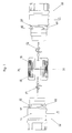
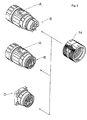
- the new modular connector can according to a selected here to illustrate the invention example according to FIG. 1 consist of a multi-pin connector 10 and a gleichpoligen socket 12 and a trained as a sleeve Arretierstoff Biology 14.
- the large-sized pins transmit, for example, a voltage of up to 630 volts and corresponding currents in connections, for example, between work machines and control cabinets. It should be noted that the polar image reproduced here has been chosen only as an example and that other polar patterns in any configuration can also be used within the scope of the invention.
- plug 10 and socket 12 The construction of plug 10 and socket 12 is mirror images of each other almost equal. Therefore, hereinafter for both parts, plug 10 and socket 12, the modular connector, the same reference numbers in the Figures 2 and 5 used and described. Both parts, plug 10 and socket 12, have the contact side towards a multi-stepped metallic hollow body 16 which shields the entire transition between the plug 10 and socket 12 grounded, and it is also one of the objectives of the invention to ensure this metallic shield over the modular connector without interruption.
- a metallic screw cap 18 is screwed onto the hollow body 10 with a frontal passage for a not shown, multi-core and shielded cable in a conventional manner, which is clamped and sealed by means of a plastic ring 20.
- a plastic ring 20 Of the cable only one overhead wire 22 is shown, which ends in the plug 10 at the opposite end in a single pin S and in the socket 12 in a single socket B. Both the individual pins S and the individual sockets B are in them concentrically surrounding and insulating sleeves H, which pass in each hollow body 16 axially inwardly into a solid, substantially cylindrical insulating body 24 made of plastic and form a molded body with this, at the assembly of the cable side into the cylindrical inner shell of the associated metallic hollow body 16 can be inserted.
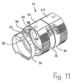
- the earth or ground contacts S E and B E are mounted in the plug 10 and in the socket 12. These are not in the insulating body 24, but in a metallic projection 30 inwardly from the most inward stepped edge R S and R B of the metallic hollow body 16. This will both on the plug side and on the socket side, the ground or ground line electrically connected to the metallic hollow bodies 16. at the same time serves the projection 30 for securing the position of the insulating body 24 in the circumferential direction, that is, their position is in the interior of the metallic hollow body 16 by means of projections 30 corresponding recesses positionally secure, and also the exact alignment of the two pole faces to each other also secured.
- An additional part orientation is effected by a lock pair 25 provided centrally in the insulating body 24.
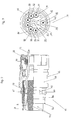
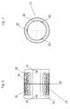
- FIGS. 1 . 6 and 7 shown locking center piece 14 in conjunction with the tapered to the contact sides of gradations of the two metallic body 16th
- the Arretierstoff Anlagen 14 consists of two identical, tightly interconnected by an inner ring 38 rings 32 and 34, which can be rotated along a circumferential parting line 36 against each other by a limited angle. At each outer inner edge of each ring 32, 34 cams 40 are formed. In the example shown here, there are three mutually offset by 120 ° cam 40. In a starting position, which is recognizable from the outside by an equal position of two flattened markings 42 and 44 in the provided with a corrugation 46 outer surface of the Arretierstoff Swisses 14, are located in the Inside the Arretierstoff Swisses 14, the three cams 40 axially aligned with each other. In this position, the locking center piece 14 - as in FIG.
- the individual sockets S, s and S individual sockets B, aligned with each other it makes sense the only applicable opening 62 clearly mark that on the visible after the complete axial mating outer surfaces of plug 10 and socket 12 each have a mark, for example in the form of a flattening A, which are aligned before mating with the markings 42 and 44 on the Arretierstoff mixes 14 must to allow the mating and fixing.
- a special feature of the invention is that the Arretierstoff Anlagen 14 can be made of injection molded plastic instead of metallic turned parts and thus much cheaper and easier without losing the shielding effect.
- the Arretierstoff Anlagen 14 can be made of injection molded plastic instead of metallic turned parts and thus much cheaper and easier without losing the shielding effect.
- the fully assembled state namely within the locking center piece 14 - even if this is made of an insulating material - the circular edges R S and R B of connector 10 and socket 12 so close to each other that a galvanic connection is formed and a shield remains without gap.
- a ground connection is ensured with pin S E and socket B E.
- FIG. 8 It is indicated schematically that various connections between couplings, bushings D, angle plugs or sockets can be secured by means of a Arretierstoff Kunststoffs 14. It is also possible to form connection chains between adapters with alternating polar patterns in order to make various plug-in systems compatible. The connections can be safely used even with the highest levels of contamination, which are often unavoidable in manufacturing companies.
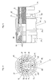
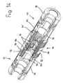
- FIGS. 9 to 14 show a development of the invention.
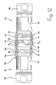
- the plastic insulating body 24 of the plug 10 engages in the assembled state on the insulating body 24 of the bush 12.
- Both insulators 24 have an in FIG. 12 indicated Montagecodtechnik 46, the socket side from the outer circumference of the insulating 24 projecting cam and plug side formed on the inner circumference of the insulating body 24 incisions into which engage the cams.
- Montagecodierung 46 and the two metallic hollow body 16 are provided with a mounting coding, which simultaneously forms a positive rotation and relieves the two insulating body 24 made of plastic.
- the contact end face R s of the hollow body 16 of the plug 10 and the contact end face R b of the hollow body 16 of the bushing 12 are provided with axially aligned steps 52 which engage in one another in the assembled state of the two coupling parts. (see. FIG. 12 ).
- FIGS. 9 to 14 Another special feature of the further education FIGS. 9 to 14 is that for securing the over the respective locking 60, 62, 64 produced, axial detent position between the plug 10 and sleeve 14 and sleeve 12 and sleeve 14 at least one reverse rotation is provided, which is formed in the embodiment of the sleeve 12.
- a plastic ring 54 is placed on the metallic hollow body 16 of the bushing 12 and axially fixed by a projection 50. From the plastic ring 54 is a radially elastically deformable nose 56 axially.
- This nose 56 is in the region of the opposite, open end face of the sleeve 14 associated with a recess 66 with a following in the direction of rotation of the sleeve 14 locking ramp 58.
- a pushbutton 70 is formed in the region of the nose 56 on the plastic ring 54, which can be pressed radially by hand to push the nose 56 inwardly, so that it can be brought out of engagement with the flank 68.
- the sleeve 14 can thus be rotated back into the starting position, in which the nose 56 engages in the recess 66, so that the sleeve 14 can be withdrawn from the hollow body 16 of the bush 12.
- a nearly identical plastic ring 54 ' is also fixed on the hollow body 16 of the plug 10, but here has no push button 70 and no nose 56 and thus does not form a reverse rotation.
- the two plastic rings 54 and 54 ' here have an additional marking function, which is that they point with different colors on different transfer tasks o. The like., For example, by a red plastic ring 54 indicates another pole number such as a blue plastic ring 54 or indicates whether the circular connector is for power or signal transmission or both.
Priority Applications (1)
| Application Number | Priority Date | Filing Date | Title |
|---|---|---|---|
| PL07123335T PL1936752T3 (pl) | 2006-12-19 | 2007-12-17 | Modułowe złącze wtykowe okrągłe |
Applications Claiming Priority (1)
| Application Number | Priority Date | Filing Date | Title |
|---|---|---|---|
| DE202006019235U DE202006019235U1 (de) | 2006-12-19 | 2006-12-19 | Modulare Rundsteckverbindung |
Publications (3)
| Publication Number | Publication Date |
|---|---|
| EP1936752A2 true EP1936752A2 (fr) | 2008-06-25 |
| EP1936752A3 EP1936752A3 (fr) | 2009-12-16 |
| EP1936752B1 EP1936752B1 (fr) | 2012-02-22 |
Family
ID=39226971
Family Applications (1)
| Application Number | Title | Priority Date | Filing Date |
|---|---|---|---|
| EP07123335A Active EP1936752B1 (fr) | 2006-12-19 | 2007-12-17 | Connecteur coaxial modulaire |
Country Status (5)
| Country | Link |
|---|---|
| EP (1) | EP1936752B1 (fr) |
| AT (1) | ATE546862T1 (fr) |
| DE (1) | DE202006019235U1 (fr) |
| ES (1) | ES2384254T3 (fr) |
| PL (1) | PL1936752T3 (fr) |
Cited By (4)
| Publication number | Priority date | Publication date | Assignee | Title |
|---|---|---|---|---|
| DE102012203459A1 (de) | 2011-11-09 | 2013-05-16 | Lq Mechatronik-Systeme Gmbh | Mehrpolige Steckverbindungseinheit für Dreiphasen-Wechselstromsysteme |
| CN106252958A (zh) * | 2016-07-29 | 2016-12-21 | 中航光电科技股份有限公司 | 一种连接器 |
| WO2017133224A1 (fr) * | 2016-02-04 | 2017-08-10 | Harting (Zhuhai) Manufacturing Co., Ltd. | Connecteur enfichable à séparation galvanique intégrée et élément de blindage |
| US10424879B2 (en) | 2015-11-06 | 2019-09-24 | Beckhoff Automation Gmbh | Hybrid plug connector |
Families Citing this family (2)
| Publication number | Priority date | Publication date | Assignee | Title |
|---|---|---|---|---|
| DE102013014290A1 (de) * | 2013-08-22 | 2015-02-26 | Sauter Feinmechanik Gmbh | Übertragungsvorrichtung für die Übertragung von Energie, wie elektrischen Strom, und/oder von elektrischen Signalen |
| DE202015105928U1 (de) | 2015-11-06 | 2015-12-07 | Beckhoff Automation Gmbh | Hybrid-Steckverbinder |
Citations (4)
| Publication number | Priority date | Publication date | Assignee | Title |
|---|---|---|---|---|
| DE69326932T2 (de) | 1992-09-19 | 2000-02-17 | Smiths Industries Plc | Verbinderanordnung |
| WO2000045469A1 (fr) | 1999-01-28 | 2000-08-03 | Badger Meter, Inc. | Prise electrique submersible a branchement/debranchement rapide et temoin de depredation |
| US6454576B1 (en) | 2000-08-22 | 2002-09-24 | Bicc General Cable Industries, Inc. | Locking electrical receptacle |
| DE202005010113U1 (de) | 2005-06-06 | 2005-09-08 | Intercontec Produkt Gmbh | Steckverbinderkupplung |
Family Cites Families (7)
| Publication number | Priority date | Publication date | Assignee | Title |
|---|---|---|---|---|
| US4111514A (en) * | 1977-06-23 | 1978-09-05 | International Telephone And Telegraph Corporation | Polarizing keying device for electrical connectors |
| US5066905A (en) * | 1988-11-14 | 1991-11-19 | Baton Labs, Inc. | Battery cable assembly with in-line switch |
| US5662488A (en) * | 1996-10-31 | 1997-09-02 | Alden; Peter H. | Quick connect coupling system for rapidly joining connectors and/or other elongated bodies |
| FR2756978B1 (fr) * | 1996-12-06 | 1999-01-08 | Radiall Sa | Connecteur circulaire modulaire |
| US6113410A (en) * | 1998-10-27 | 2000-09-05 | Lucent Technologies Inc. | RF connector lock |
| DE19941509A1 (de) * | 1999-08-31 | 2001-03-29 | Interconnectron Ges Fuer Ind S | Rundsteckverbinder zur Herstellung elektrischer Leitungsverbindungen |
| DE19941518A1 (de) * | 1999-08-31 | 2001-03-01 | Interconnectron Ges Fuer Ind S | Rundsteckverbinder zur Herstellung elektrischer Leitungsverbindungen |
-
2006
- 2006-12-19 DE DE202006019235U patent/DE202006019235U1/de not_active Expired - Lifetime
-
2007
- 2007-12-17 AT AT07123335T patent/ATE546862T1/de active
- 2007-12-17 ES ES07123335T patent/ES2384254T3/es active Active
- 2007-12-17 EP EP07123335A patent/EP1936752B1/fr active Active
- 2007-12-17 PL PL07123335T patent/PL1936752T3/pl unknown
Patent Citations (4)
| Publication number | Priority date | Publication date | Assignee | Title |
|---|---|---|---|---|
| DE69326932T2 (de) | 1992-09-19 | 2000-02-17 | Smiths Industries Plc | Verbinderanordnung |
| WO2000045469A1 (fr) | 1999-01-28 | 2000-08-03 | Badger Meter, Inc. | Prise electrique submersible a branchement/debranchement rapide et temoin de depredation |
| US6454576B1 (en) | 2000-08-22 | 2002-09-24 | Bicc General Cable Industries, Inc. | Locking electrical receptacle |
| DE202005010113U1 (de) | 2005-06-06 | 2005-09-08 | Intercontec Produkt Gmbh | Steckverbinderkupplung |
Cited By (14)
| Publication number | Priority date | Publication date | Assignee | Title |
|---|---|---|---|---|
| EP2777096B1 (fr) | 2011-11-09 | 2018-04-04 | LQ Mechatronik-Systeme GmbH | Unité de connexion à fiches multipolaire pour systèmes électriques triphasés |
| DE102012203459A1 (de) | 2011-11-09 | 2013-05-16 | Lq Mechatronik-Systeme Gmbh | Mehrpolige Steckverbindungseinheit für Dreiphasen-Wechselstromsysteme |
| US20140295690A1 (en) * | 2011-11-09 | 2014-10-02 | José Quero pacheco | Multi-pole plug connection unit for three-phase alternating current systems |
| CN104170179A (zh) * | 2011-11-09 | 2014-11-26 | Lq机电系统有限责任公司 | 用于三相交流系统的多极插塞连接单元 |
| DE202012013360U1 (de) | 2011-11-09 | 2016-07-15 | Lq Mechatronik-Systeme Gmbh | Mehrpolige Steckverbindungseinheit für Dreiphasen-Wechselstromsysteme |
| US9437970B2 (en) | 2011-11-09 | 2016-09-06 | Lq Mechatronik-Systeme Gmbh | Multi-pole plug connection unit for three-phase alternating current systems |
| WO2013068509A1 (fr) | 2011-11-09 | 2013-05-16 | Lq Mechatronik-Systeme Gmbh | Unité de connexion à fiches multipolaire pour systèmes électriques triphasés |
| EP2777096B2 (fr) † | 2011-11-09 | 2021-06-16 | LQ Mechatronik-Systeme GmbH | Unité de connexion à fiches multipolaire pour systèmes électriques triphasés |
| US10424879B2 (en) | 2015-11-06 | 2019-09-24 | Beckhoff Automation Gmbh | Hybrid plug connector |
| WO2017132959A1 (fr) * | 2016-02-04 | 2017-08-10 | Harting (Zhuhai) Manufacturing Co., Ltd. | Connecteur enfichable à séparation galvanique intégrée |
| WO2017133224A1 (fr) * | 2016-02-04 | 2017-08-10 | Harting (Zhuhai) Manufacturing Co., Ltd. | Connecteur enfichable à séparation galvanique intégrée et élément de blindage |
| US10418756B2 (en) | 2016-02-04 | 2019-09-17 | Harting (Zhuhai) Manufacturing Co., Ltd. | Plug connector with integrated galvanic separation and shielding element |
| KR20180122339A (ko) * | 2016-02-04 | 2018-11-12 | 하르팅 (주하이) 매뉴팩처링 컴퍼니 리미티드 | 일체형 갈바닉 분리부를 갖는 플러그 커넥터 그리고 차폐 요소 |
| CN106252958A (zh) * | 2016-07-29 | 2016-12-21 | 中航光电科技股份有限公司 | 一种连接器 |
Also Published As
| Publication number | Publication date |
|---|---|
| EP1936752B1 (fr) | 2012-02-22 |
| PL1936752T3 (pl) | 2012-08-31 |
| ES2384254T3 (es) | 2012-07-03 |
| EP1936752A3 (fr) | 2009-12-16 |
| DE202006019235U1 (de) | 2008-05-08 |
| ATE546862T1 (de) | 2012-03-15 |
Similar Documents
| Publication | Publication Date | Title |
|---|---|---|
| EP0551302B1 (fr) | Dispositif pour outils electriques | |
| DE2549597A1 (de) | Kupplungsanordnung fuer verbindbare enden elektrischer leitungen | |
| EP2777096B2 (fr) | Unité de connexion à fiches multipolaire pour systèmes électriques triphasés | |
| EP2754211B1 (fr) | Connecteur à contacts protégés | |
| WO2017076781A1 (fr) | Connecteur hybride | |
| EP1936752B1 (fr) | Connecteur coaxial modulaire | |
| DE3026386A1 (de) | Steckverbindung mit visueller, tastbarer und hoerbarer anzeige | |
| EP2043202A1 (fr) | Connecteur à fiche électrique ou optique | |
| DE102019114257B4 (de) | Steckverbinder mit Verriegelungssystem | |
| EP1570553B1 (fr) | Dispositif de connexion par enfichage | |
| DE102006001130A1 (de) | Steckvorrichtung nach EN 60 309 mit einem Drehkörper zur Abdichtung und Verriegelung ohne Klappdeckel | |
| DE2215757A1 (de) | Koaxialsteckverbindung | |
| WO2019076620A1 (fr) | Partie de connecteur enfichable munie d'un élément de verrouillage | |
| DE2308316A1 (de) | Elektrischer steckverbinder | |
| DE2359752C3 (de) | Explosionssichere Kupplungssteckvorrichtung | |
| DE1475784C3 (de) | Unverwechselbare Anschlußkupplung und Werkzeug zu ihrer Einstellung | |
| DE202005017981U1 (de) | Kontakthalterung für elektrische Steckverbinder | |
| DE102019114262B3 (de) | Steckverbinder mit Verriegelungssystem | |
| EP2824775A1 (fr) | Unité isolée de connecteurs à fiche ronds dotée de contacts à fiche disposés de façon symétrique | |
| WO2022053098A1 (fr) | Système de connecteur enfichable doté de connexion modulaire à déconnexion rapide | |
| DE7720275U1 (de) | Elektrische leitungskupplung | |
| EP1569288A1 (fr) | Fiche de connection pour recharge avec un adaptateur pour emboitement | |
| DE19617201A1 (de) | Muffensteckverbindung | |
| DE7731086U1 (de) | Elektrische Steckverbindung | |
| DE2646063A1 (de) | Kupplungsgehaeuse fuer verbinder |
Legal Events
| Date | Code | Title | Description |
|---|---|---|---|
| PUAI | Public reference made under article 153(3) epc to a published international application that has entered the european phase |
Free format text: ORIGINAL CODE: 0009012 |
|
| AK | Designated contracting states |
Kind code of ref document: A2 Designated state(s): AT BE BG CH CY CZ DE DK EE ES FI FR GB GR HU IE IS IT LI LT LU LV MC MT NL PL PT RO SE SI SK TR |
|
| AX | Request for extension of the european patent |
Extension state: AL BA HR MK RS |
|
| RAP1 | Party data changed (applicant data changed or rights of an application transferred) |
Owner name: INTERCONTED PFEIFFER STECKVERBINDUNGEN GMBH |
|
| PUAL | Search report despatched |
Free format text: ORIGINAL CODE: 0009013 |
|
| AK | Designated contracting states |
Kind code of ref document: A3 Designated state(s): AT BE BG CH CY CZ DE DK EE ES FI FR GB GR HU IE IS IT LI LT LU LV MC MT NL PL PT RO SE SI SK TR |
|
| AX | Request for extension of the european patent |
Extension state: AL BA HR MK RS |
|
| RIC1 | Information provided on ipc code assigned before grant |
Ipc: H01R 13/625 20060101AFI20091111BHEP |
|
| 17P | Request for examination filed |
Effective date: 20100608 |
|
| AKX | Designation fees paid |
Designated state(s): AT BE BG CH CY CZ DE DK EE ES FI FR GB GR HU IE IS IT LI LT LU LV MC MT NL PL PT RO SE SI SK TR |
|
| GRAP | Despatch of communication of intention to grant a patent |
Free format text: ORIGINAL CODE: EPIDOSNIGR1 |
|
| GRAS | Grant fee paid |
Free format text: ORIGINAL CODE: EPIDOSNIGR3 |
|
| GRAA | (expected) grant |
Free format text: ORIGINAL CODE: 0009210 |
|
| RAP1 | Party data changed (applicant data changed or rights of an application transferred) |
Owner name: LQ MECHATRONIK-SYSTEME GMBH |
|
| AK | Designated contracting states |
Kind code of ref document: B1 Designated state(s): AT BE BG CH CY CZ DE DK EE ES FI FR GB GR HU IE IS IT LI LT LU LV MC MT NL PL PT RO SE SI SK TR |
|
| REG | Reference to a national code |
Ref country code: GB Ref legal event code: FG4D Free format text: NOT ENGLISH |
|
| REG | Reference to a national code |
Ref country code: CH Ref legal event code: EP |
|
| REG | Reference to a national code |
Ref country code: AT Ref legal event code: REF Ref document number: 546862 Country of ref document: AT Kind code of ref document: T Effective date: 20120315 |
|
| REG | Reference to a national code |
Ref country code: IE Ref legal event code: FG4D Free format text: LANGUAGE OF EP DOCUMENT: GERMAN |
|
| REG | Reference to a national code |
Ref country code: DE Ref legal event code: R096 Ref document number: 502007009314 Country of ref document: DE Effective date: 20120419 |
|
| REG | Reference to a national code |
Ref country code: SE Ref legal event code: TRGR |
|
| REG | Reference to a national code |
Ref country code: NL Ref legal event code: T3 |
|
| REG | Reference to a national code |
Ref country code: CH Ref legal event code: NV Representative=s name: ZIMMERLI, WAGNER & PARTNER AG |
|
| REG | Reference to a national code |
Ref country code: ES Ref legal event code: FG2A Ref document number: 2384254 Country of ref document: ES Kind code of ref document: T3 Effective date: 20120703 |
|
| LTIE | Lt: invalidation of european patent or patent extension |
Effective date: 20120222 |
|
| PG25 | Lapsed in a contracting state [announced via postgrant information from national office to epo] |
Ref country code: IS Free format text: LAPSE BECAUSE OF FAILURE TO SUBMIT A TRANSLATION OF THE DESCRIPTION OR TO PAY THE FEE WITHIN THE PRESCRIBED TIME-LIMIT Effective date: 20120622 Ref country code: LT Free format text: LAPSE BECAUSE OF FAILURE TO SUBMIT A TRANSLATION OF THE DESCRIPTION OR TO PAY THE FEE WITHIN THE PRESCRIBED TIME-LIMIT Effective date: 20120222 |
|
| PG25 | Lapsed in a contracting state [announced via postgrant information from national office to epo] |
Ref country code: LV Free format text: LAPSE BECAUSE OF FAILURE TO SUBMIT A TRANSLATION OF THE DESCRIPTION OR TO PAY THE FEE WITHIN THE PRESCRIBED TIME-LIMIT Effective date: 20120222 Ref country code: GR Free format text: LAPSE BECAUSE OF FAILURE TO SUBMIT A TRANSLATION OF THE DESCRIPTION OR TO PAY THE FEE WITHIN THE PRESCRIBED TIME-LIMIT Effective date: 20120523 Ref country code: PT Free format text: LAPSE BECAUSE OF FAILURE TO SUBMIT A TRANSLATION OF THE DESCRIPTION OR TO PAY THE FEE WITHIN THE PRESCRIBED TIME-LIMIT Effective date: 20120622 |
|
| REG | Reference to a national code |
Ref country code: PL Ref legal event code: T3 |
|
| REG | Reference to a national code |
Ref country code: IE Ref legal event code: FD4D |
|
| PG25 | Lapsed in a contracting state [announced via postgrant information from national office to epo] |
Ref country code: CY Free format text: LAPSE BECAUSE OF FAILURE TO SUBMIT A TRANSLATION OF THE DESCRIPTION OR TO PAY THE FEE WITHIN THE PRESCRIBED TIME-LIMIT Effective date: 20120222 |
|
| PG25 | Lapsed in a contracting state [announced via postgrant information from national office to epo] |
Ref country code: IE Free format text: LAPSE BECAUSE OF FAILURE TO SUBMIT A TRANSLATION OF THE DESCRIPTION OR TO PAY THE FEE WITHIN THE PRESCRIBED TIME-LIMIT Effective date: 20120222 Ref country code: DK Free format text: LAPSE BECAUSE OF FAILURE TO SUBMIT A TRANSLATION OF THE DESCRIPTION OR TO PAY THE FEE WITHIN THE PRESCRIBED TIME-LIMIT Effective date: 20120222 Ref country code: EE Free format text: LAPSE BECAUSE OF FAILURE TO SUBMIT A TRANSLATION OF THE DESCRIPTION OR TO PAY THE FEE WITHIN THE PRESCRIBED TIME-LIMIT Effective date: 20120222 Ref country code: SI Free format text: LAPSE BECAUSE OF FAILURE TO SUBMIT A TRANSLATION OF THE DESCRIPTION OR TO PAY THE FEE WITHIN THE PRESCRIBED TIME-LIMIT Effective date: 20120222 Ref country code: RO Free format text: LAPSE BECAUSE OF FAILURE TO SUBMIT A TRANSLATION OF THE DESCRIPTION OR TO PAY THE FEE WITHIN THE PRESCRIBED TIME-LIMIT Effective date: 20120222 |
|
| PG25 | Lapsed in a contracting state [announced via postgrant information from national office to epo] |
Ref country code: SK Free format text: LAPSE BECAUSE OF FAILURE TO SUBMIT A TRANSLATION OF THE DESCRIPTION OR TO PAY THE FEE WITHIN THE PRESCRIBED TIME-LIMIT Effective date: 20120222 |
|
| PLBE | No opposition filed within time limit |
Free format text: ORIGINAL CODE: 0009261 |
|
| STAA | Information on the status of an ep patent application or granted ep patent |
Free format text: STATUS: NO OPPOSITION FILED WITHIN TIME LIMIT |
|
| 26N | No opposition filed |
Effective date: 20121123 |
|
| REG | Reference to a national code |
Ref country code: DE Ref legal event code: R097 Ref document number: 502007009314 Country of ref document: DE Effective date: 20121123 |
|
| PG25 | Lapsed in a contracting state [announced via postgrant information from national office to epo] |
Ref country code: MC Free format text: LAPSE BECAUSE OF NON-PAYMENT OF DUE FEES Effective date: 20121231 Ref country code: BG Free format text: LAPSE BECAUSE OF FAILURE TO SUBMIT A TRANSLATION OF THE DESCRIPTION OR TO PAY THE FEE WITHIN THE PRESCRIBED TIME-LIMIT Effective date: 20120522 |
|
| PG25 | Lapsed in a contracting state [announced via postgrant information from national office to epo] |
Ref country code: MT Free format text: LAPSE BECAUSE OF FAILURE TO SUBMIT A TRANSLATION OF THE DESCRIPTION OR TO PAY THE FEE WITHIN THE PRESCRIBED TIME-LIMIT Effective date: 20120222 |
|
| REG | Reference to a national code |
Ref country code: CH Ref legal event code: NV Representative=s name: WAGNER PATENT AG, CH |
|
| PG25 | Lapsed in a contracting state [announced via postgrant information from national office to epo] |
Ref country code: LU Free format text: LAPSE BECAUSE OF NON-PAYMENT OF DUE FEES Effective date: 20121217 |
|
| PG25 | Lapsed in a contracting state [announced via postgrant information from national office to epo] |
Ref country code: HU Free format text: LAPSE BECAUSE OF FAILURE TO SUBMIT A TRANSLATION OF THE DESCRIPTION OR TO PAY THE FEE WITHIN THE PRESCRIBED TIME-LIMIT Effective date: 20071217 |
|
| REG | Reference to a national code |
Ref country code: FR Ref legal event code: PLFP Year of fee payment: 9 |
|
| REG | Reference to a national code |
Ref country code: FR Ref legal event code: PLFP Year of fee payment: 10 |
|
| REG | Reference to a national code |
Ref country code: FR Ref legal event code: PLFP Year of fee payment: 11 |
|
| PGFP | Annual fee paid to national office [announced via postgrant information from national office to epo] |
Ref country code: PL Payment date: 20221209 Year of fee payment: 16 Ref country code: BE Payment date: 20221220 Year of fee payment: 16 |
|
| PGFP | Annual fee paid to national office [announced via postgrant information from national office to epo] |
Ref country code: ES Payment date: 20230119 Year of fee payment: 16 Ref country code: CH Payment date: 20230103 Year of fee payment: 16 |
|
| PGFP | Annual fee paid to national office [announced via postgrant information from national office to epo] |
Ref country code: IT Payment date: 20221230 Year of fee payment: 16 |
|
| PGFP | Annual fee paid to national office [announced via postgrant information from national office to epo] |
Ref country code: GB Payment date: 20231220 Year of fee payment: 17 |
|
| PGFP | Annual fee paid to national office [announced via postgrant information from national office to epo] |
Ref country code: TR Payment date: 20231208 Year of fee payment: 17 Ref country code: SE Payment date: 20231219 Year of fee payment: 17 Ref country code: NL Payment date: 20231219 Year of fee payment: 17 Ref country code: FR Payment date: 20231219 Year of fee payment: 17 Ref country code: FI Payment date: 20231218 Year of fee payment: 17 Ref country code: DE Payment date: 20231219 Year of fee payment: 17 Ref country code: CZ Payment date: 20231204 Year of fee payment: 17 Ref country code: AT Payment date: 20231214 Year of fee payment: 17 |
|
| PGFP | Annual fee paid to national office [announced via postgrant information from national office to epo] |
Ref country code: PL Payment date: 20231117 Year of fee payment: 17 Ref country code: BE Payment date: 20231218 Year of fee payment: 17 |
|
| PGFP | Annual fee paid to national office [announced via postgrant information from national office to epo] |
Ref country code: ES Payment date: 20240118 Year of fee payment: 17 |