EP1936040B1 - Dispositif de voirie - Google Patents
Dispositif de voirie Download PDFInfo
- Publication number
- EP1936040B1 EP1936040B1 EP07291550A EP07291550A EP1936040B1 EP 1936040 B1 EP1936040 B1 EP 1936040B1 EP 07291550 A EP07291550 A EP 07291550A EP 07291550 A EP07291550 A EP 07291550A EP 1936040 B1 EP1936040 B1 EP 1936040B1
- Authority
- EP
- European Patent Office
- Prior art keywords
- frame
- covering element
- corners
- cleaning device
- support surfaces
- Prior art date
- Legal status (The legal status is an assumption and is not a legal conclusion. Google has not performed a legal analysis and makes no representation as to the accuracy of the status listed.)
- Active
Links
Images


Classifications
-
- E—FIXED CONSTRUCTIONS
- E02—HYDRAULIC ENGINEERING; FOUNDATIONS; SOIL SHIFTING
- E02D—FOUNDATIONS; EXCAVATIONS; EMBANKMENTS; UNDERGROUND OR UNDERWATER STRUCTURES
- E02D29/00—Independent underground or underwater structures; Retaining walls
- E02D29/12—Manhole shafts; Other inspection or access chambers; Accessories therefor
- E02D29/14—Covers for manholes or the like; Frames for covers
Definitions
- the frame has two first reliefs each having a horizontal frame surface, parallel to the general plane of the device.
- the frame is further provided with two second frame reliefs having inclined bearing surfaces inclined with respect to the general plane as well as counter-bearing surfaces inclined both with respect to the general plane and with respect to the surfaces of the frame. sloping support.
- the covering element comprises two first reliefs having parallel bearing surfaces complementary to the horizontal frame surfaces.
- the covering element also has two second reliefs having complementary bearing and abutment surfaces to the sloped bearing surfaces and the counter-bearing surfaces of the second frame reliefs.
- the known road device allows the insertion of the covering element in the frame in only one configuration.
- the orientation of the buffer or grid is important compared to the direction of movement of the vehicles.
- the invention aims to increase the flexibility of use of the known road device.
- the subject of the invention is a roadway device of the aforementioned type, characterized in that the frame further comprises two third frame surfaces complementary to the first bearing surfaces and associated with two third frame corners, of which at least one corner is different from the first two frame corners, and two fourth frame surfaces complementary to the second bearing surfaces and associated with fourth frame corners, at least one corner of which is different from the two second frame corners.
- drain 1 made for example of ductile iron, but can be used with any road device having a frame and a covering element.
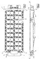
- the drain 1 comprises on the one hand a covering element, in the form of a grid 2, and on the other hand a housing 4, forming a frame, which is adapted to support the covering element.
- the housing 4 In the mounted state, the housing 4 is disposed in the ground 6 in such a way that the drain 1 defines a general plane PP which is parallel to the surface 8 of the ground 6 (see FIG. Figure 5 ).
- the upper surfaces of the housing 4 and the gate 2 are flush with the surface 8 of the ground when the gate 2 is in the closed position on the housing 4, that is to say in the closed state of the drain.
- the grid 2 has a generally rectangular shape and has through openings 10 adapted to allow rain water into the housing 4, the latter serving both siphon and decanter.
- the grid 2 defines two adjacent first corners 12 and two second corners 14 adjacent and opposite the first corners 12.
- the grid 2 is further provided with two first bearing surfaces 16 each of which is associated with one of the first corners 12.
- first bearing surfaces 16 each of which is associated with one of the first corners 12.
- associated means that the corresponding surface is closer to the corner. associated only with all other corners.
- the first bearing surfaces 16 extend parallel to the general plane P-P, are coplanar and are in contact with the casing 4 in the closed state.
- the grid 2 is further provided with two second bearing surfaces 18 each of which is associated with one of the second corners 14. These second bearing surfaces 18 are inclined relative to the general plane PP by an angle ⁇ .
- the angle of inclination ⁇ with respect to the plane PP is for example between 45 ° and 85 °
- the second bearing surfaces 18 of the grid 2 are parallel and coplanar. They have a normal which has a component directed downwards, thus towards the casing 4 in the closed state, as well as a component directed towards the outside of the grid.
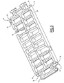
- the housing 4 has two adjacent first frame corners 20 and two second frame corners 22 which are opposite corners to the first frame corners 20.
- the housing 4 has two first coplanar parallel coplanar surfaces 24 extending parallel to the general plane P-P. These first frame surfaces 24 face the gate 2 in the closed state and are associated with the first frame corners 20.
- the first frame surfaces 24 are complementary to the first bearing surfaces 16 of the grid 2, it is that is, in the closed state of the grid 2, the first bearing surfaces 16 can be applied to the first frame surfaces 24:
- the housing 4 has two second frame surfaces 26.
- These second frame surfaces 26 are associated with the second corners 22 of the housing 4, are parallel and are inclined relative to the general plane PP by an angle corresponding to the angle ⁇ previously defined.
- the second frame surfaces 26 have a normal having a component directed upwards, thus towards the grid 2, as well as a component directed towards the first frame corner 20 located opposite.
- the second frame surfaces 26 are coplanar.
- the two second frame surfaces 26 are complementary to the second bearing surfaces 18 of the grid 2. In the closed state of the grid 2, the second bearing surfaces 18 can be applied against the second frame surfaces 26.
- the grid 2 further comprises two counter-bearing surfaces 29, each of which is associated with one of the second corners 14 of the covering element, facing away from the second bearing surface 18 associated with this second corner. 14 and inclined relative thereto an angle which is open towards the inside of the grid 2.
- the counter-support surfaces 29 of the grid are adapted to be applied on two first complementary counter-support surfaces 29A which are each arranged on a projection of the casing 4 associated with a second wedge of frame 22, each counter-bearing surface 29A being arranged opposite the second frame surface 26 associated with this second frame corner 22 and forming with this second frame surface 26 an open angle towards the inside of the casing 4.
- each counter-support surface 29 and the second surface 18 associated with it may also be open towards the outside of the gate, in which case the angle between the complementary abutment surfaces 29A and the second associated frame surfaces 26 will also be open towards the outside of the housing 4.
- the housing 4 further has two third frame surfaces 30 complementary to the first bearing surfaces 16 of the grid and associated with the second corners 22 of the housing 4.
- the third frame surfaces 30 are parallel to the general plane P-P and coplanar. Each of them is arranged on a relief forming the second frame surface 26.
- the housing 4 also has two fourth frame surfaces 32 which are complementary to the second bearing surfaces 18 of the grid and which are associated with the first frame corners 20. Each of them is arranged on a relief forming the first frame surface 24.
- the fourth frame surfaces 32 are inclined with respect to the general plane PP of the same angle ⁇ as the second frame surfaces 26 and are arranged facing one another. vis-à-vis them.
- the third frame surfaces 30 are associated with third frame corners
- the fourth frame surfaces 32 are associated with fourth frame corners.
- the third frame corners are the second frame corners 22 and the fourth frame corners are the first frame corners 20.
- the casing 4 also has two second counter-support surfaces 29B, each disposed on a projection associated with a first frame corner 20, each counter-support surface 29B being arranged facing the fourth frame surface 32 associated with this housing.
- first corner of frame 20 and forming with this fourth frame surface 32 an open angle towards the inside of the housing (see Figure 4 ).
- These second counter-bearing surfaces 29B are complementary to the counter-support surfaces 29 of the grid 2 and can thus cooperate with them.
- the drain 1 further comprises a hinge 40 which is adapted to allow the tilting of the gate 2 relative to the housing 4 between an open position and a closed position about a tilting axis XX which extends parallel to the general plane PP.
- the hinge 40 is provided with two first frame knuckles 42 integral with the housing 4 and two gate knuckles 44 fixed to the grid 2 and adapted to cooperate with the first frame knuckles 42.
- the first frame hinges 42 are associated with the first frame corners 20.
- These first frame hinges 42 are made here as hinge housings which are adapted to receive hinge pins forming the gate hinges 44.
- the frame knuckles 42 also have dimensions greater than those of the gate knuckles 44 to allow the rotation of the grid 2 about the axis XX as well as its translation with respect to the housing 4, this translation thus allowing the cooperation of the surfaces. bearing 16, 18 of the grid with the complementary frame surfaces 24, 26.
- the hinge 40 thus has a degree of freedom allowing a displacement of the grid 2 parallel to the general plane P-P and in a radial direction relative to the axis of tilting X-X.
- the housing 4 comprises two second frame hinges 46 associated with the second frame corners 22 and adapted to cooperate with the gate hinges 44 so as to allow the gate to rotate relative to the housing 4 between an open position and a closed position about another axis of tilting which extends parallel to the general plane PP and which is located opposite the axis XX.
- the second frame knuckles 46 form receiving housings of the hinge pins of the gate knuckles 44 and have dimensions greater than those of the gate knuckles 44, so as to allow translation of the gate parallel to the plane PP and perpendicular to the axis of rotation.
- the drain 1 also comprises locking means adapted to lock the gate 2 in the closed position on the housing 4.
- these locking means comprise an elastic finger 52 disposed on the gate 2 and movable between a position of locking and a release position. The finger 52 is movable in a direction parallel to the general plane P-P when the gate 2 is in the closed state.
- these locking means comprise a first locking surface 54 disposed on the housing 4 closer to the second frame hinges 46 than the first frame hinges 42 and adapted to cooperate with the finger 52 and to oppose the lifting of the gate when the gate 2 is in the closed state and when the gate knuckles 44 are arranged in the first frame knuckles 42.
- the housing 4 further comprises a second locking surface 56, disposed closer to the first frame knuckles 42 as second frame knuckles 46, and which is adapted to cooperate with the finger 52 and to oppose the lifting of the grid when the gate knuckles 44 are arranged in the second frame knuckles 46.
- Drain 1 works as follows:
- the housing 4 is fixed in a given position in the ground 6.
- the knuckles 44 of the grid 2 are inserted into the first frame knuckles 42, for example when the direction of vehicle traffic is from left to right on the Figure 5 .
- the gate 2 is open, it is automatically switched to its closed configuration in case of accidental passage of a vehicle.
- the grid 2 in closing position, the grid 2 then applies with its first bearing surfaces 16 against the first frame surfaces 24 and with its two second surfaces 18 against the second frame surfaces 26, while the locking elastic finger 52 is engaged with the first locking surface 54 of the housing 4 and thus ensures the locking of the grid 2 on the housing 4.
- the counter-support surfaces 29 of the grid can then cooperate with the second counter-support surfaces 29B of the housing 4 and thus ensure contact of the grid 2 with the housing 4 at four points of support, the counter surfaces support 29 and 29B for this purpose fulfilling the same function as that described above for the bearing surfaces 29 and 29A.
Landscapes
- Engineering & Computer Science (AREA)
- Environmental & Geological Engineering (AREA)
- Life Sciences & Earth Sciences (AREA)
- General Life Sciences & Earth Sciences (AREA)
- Mining & Mineral Resources (AREA)
- Paleontology (AREA)
- Civil Engineering (AREA)
- General Engineering & Computer Science (AREA)
- Structural Engineering (AREA)
- Road Signs Or Road Markings (AREA)
- Baking, Grill, Roasting (AREA)
Applications Claiming Priority (1)
| Application Number | Priority Date | Filing Date | Title |
|---|---|---|---|
| FR0611317A FR2910501B1 (fr) | 2006-12-22 | 2006-12-22 | Dispositif de voirie comportant un element de recouvrement et un cadre adapte pour supporter l'element de recouvrement dans differentes configurations, suivant notamment le sens de la circulation |
Publications (2)
| Publication Number | Publication Date |
|---|---|
| EP1936040A1 EP1936040A1 (fr) | 2008-06-25 |
| EP1936040B1 true EP1936040B1 (fr) | 2011-06-01 |
Family
ID=38229374
Family Applications (1)
| Application Number | Title | Priority Date | Filing Date |
|---|---|---|---|
| EP07291550A Active EP1936040B1 (fr) | 2006-12-22 | 2007-12-18 | Dispositif de voirie |
Country Status (4)
| Country | Link |
|---|---|
| EP (1) | EP1936040B1 (es) |
| AT (1) | ATE511576T1 (es) |
| ES (1) | ES2367397T3 (es) |
| FR (1) | FR2910501B1 (es) |
Family Cites Families (3)
| Publication number | Priority date | Publication date | Assignee | Title |
|---|---|---|---|---|
| FR2760765B1 (fr) * | 1997-03-11 | 1999-04-30 | Pont A Mousson | Dispositif de voirie de forme carree ou rectangulaire comprenant un cadre support et un element de recouvrement |
| FR2770861B1 (fr) | 1997-11-13 | 2000-01-14 | Pont A Mousson | Dispositif de voirie de forme carree ou rectangulaire comprenant un cadre support et un element de recouvrement |
| JP4521998B2 (ja) * | 2001-01-24 | 2010-08-11 | 虹技株式会社 | 地下構造物用蓋の開閉構造 |
-
2006
- 2006-12-22 FR FR0611317A patent/FR2910501B1/fr not_active Expired - Fee Related
-
2007
- 2007-12-18 AT AT07291550T patent/ATE511576T1/de not_active IP Right Cessation
- 2007-12-18 EP EP07291550A patent/EP1936040B1/fr active Active
- 2007-12-18 ES ES07291550T patent/ES2367397T3/es active Active
Also Published As
| Publication number | Publication date |
|---|---|
| FR2910501B1 (fr) | 2009-03-27 |
| ATE511576T1 (de) | 2011-06-15 |
| EP1936040A1 (fr) | 2008-06-25 |
| ES2367397T3 (es) | 2011-11-03 |
| FR2910501A1 (fr) | 2008-06-27 |
Similar Documents
| Publication | Publication Date | Title |
|---|---|---|
| EP2376714B1 (fr) | Trappe d'acces munie d'un cadre et d'un tampon | |
| CA2577042C (fr) | Dispositif permettant d'obturer un cadre, comprenant un panneau monte articule amovible sur le cadre | |
| EP2563976B1 (fr) | Dispositif de voirie | |
| FR2839992A1 (fr) | Dispositif de fermeture d'une ouverture, en particulier regard de chaussee | |
| FR2722527A1 (fr) | Dispositif de verrouillage pour chassis a frappe | |
| FR2703578A1 (fr) | Charnière pour le montage d'un ensemble siège-couvercle sur une cuvette de cabinet. | |
| FR2550574A1 (fr) | Ferrure a tige active ou tige de commande pour fenetres, portes ou autres elements du meme genre | |
| EP1936040B1 (fr) | Dispositif de voirie | |
| EP3052705B1 (fr) | Ensemble de tampons, dispositif de voirie et utilisation correspondants | |
| EP0060794A2 (fr) | Corbeille à papier | |
| FR2804464A1 (fr) | Dispositif de solidarisation et mecanisme de manoeuvre d'une installation de fermeture ou de protection solaire comprenant un tel dispositif | |
| EP1297225B1 (fr) | Dispositif de voirie a couvercle articule | |
| EP1948499B1 (fr) | Dispositif d'ecartement securise a l'arrachement | |
| EP0973975B1 (fr) | Dispositif de voirie de forme carree ou rectangulaire comprenant un cadre support et un element de recouvrement | |
| FR2915952A1 (fr) | Ensemble d'extremite de vehicule automobile, procede de montage et vehicule automobile associe. | |
| EP3008263B1 (fr) | Dispositif d'accouplement de deux demi-cylindres | |
| EP2721223B1 (fr) | Dispositif de voirie | |
| EP2167736B1 (fr) | Dispositif de voirie à cadre de support et élément de couronnement, tel qu'un tampon ou couvercle, monté articulé à basculement sur le cadre | |
| FR2685715A1 (fr) | Dispositif perfectionne de verrouillage d'un tampon sur un cadre, pour regard de chaussee ou analogue. | |
| EP1052337B1 (fr) | Bouche d'égout à couvercle et grille articulés et verrouillés | |
| FR2477624A1 (fr) | Palier d'angle pour battant de porte ou fenetre | |
| EP1748137B1 (fr) | Charnière réglable | |
| EP1400634B1 (fr) | Dispositif de liaison d'une grille sur un caniveau et outil de demontage correspondant | |
| FR2814182A1 (fr) | Dispositif articule d'obturation d'un regard et element de charniere pour un tel dispositif | |
| FR2761753A1 (fr) | Dispositif d'assemblage en angle |
Legal Events
| Date | Code | Title | Description |
|---|---|---|---|
| PUAI | Public reference made under article 153(3) epc to a published international application that has entered the european phase |
Free format text: ORIGINAL CODE: 0009012 |
|
| AK | Designated contracting states |
Kind code of ref document: A1 Designated state(s): AT BE BG CH CY CZ DE DK EE ES FI FR GB GR HU IE IS IT LI LT LU LV MC MT NL PL PT RO SE SI SK TR |
|
| AX | Request for extension of the european patent |
Extension state: AL BA HR MK RS |
|
| 17P | Request for examination filed |
Effective date: 20081208 |
|
| AKX | Designation fees paid |
Designated state(s): AT BE BG CH CY CZ DE DK EE ES FI FR GB GR HU IE IS IT LI LT LU LV MC MT NL PL PT RO SE SI SK TR |
|
| GRAP | Despatch of communication of intention to grant a patent |
Free format text: ORIGINAL CODE: EPIDOSNIGR1 |
|
| GRAS | Grant fee paid |
Free format text: ORIGINAL CODE: EPIDOSNIGR3 |
|
| GRAA | (expected) grant |
Free format text: ORIGINAL CODE: 0009210 |
|
| AK | Designated contracting states |
Kind code of ref document: B1 Designated state(s): AT BE BG CH CY CZ DE DK EE ES FI FR GB GR HU IE IS IT LI LT LU LV MC MT NL PL PT RO SE SI SK TR |
|
| REG | Reference to a national code |
Ref country code: GB Ref legal event code: FG4D Free format text: NOT ENGLISH |
|
| REG | Reference to a national code |
Ref country code: CH Ref legal event code: EP |
|
| REG | Reference to a national code |
Ref country code: IE Ref legal event code: FG4D Free format text: LANGUAGE OF EP DOCUMENT: FRENCH |
|
| REG | Reference to a national code |
Ref country code: DE Ref legal event code: R096 Ref document number: 602007014943 Country of ref document: DE Effective date: 20110714 |
|
| REG | Reference to a national code |
Ref country code: NL Ref legal event code: VDEP Effective date: 20110601 |
|
| PG25 | Lapsed in a contracting state [announced via postgrant information from national office to epo] |
Ref country code: SE Free format text: LAPSE BECAUSE OF FAILURE TO SUBMIT A TRANSLATION OF THE DESCRIPTION OR TO PAY THE FEE WITHIN THE PRESCRIBED TIME-LIMIT Effective date: 20110601 Ref country code: LT Free format text: LAPSE BECAUSE OF FAILURE TO SUBMIT A TRANSLATION OF THE DESCRIPTION OR TO PAY THE FEE WITHIN THE PRESCRIBED TIME-LIMIT Effective date: 20110601 |
|
| REG | Reference to a national code |
Ref country code: ES Ref legal event code: FG2A Ref document number: 2367397 Country of ref document: ES Kind code of ref document: T3 Effective date: 20111103 |
|
| PG25 | Lapsed in a contracting state [announced via postgrant information from national office to epo] |
Ref country code: AT Free format text: LAPSE BECAUSE OF FAILURE TO SUBMIT A TRANSLATION OF THE DESCRIPTION OR TO PAY THE FEE WITHIN THE PRESCRIBED TIME-LIMIT Effective date: 20110601 Ref country code: FI Free format text: LAPSE BECAUSE OF FAILURE TO SUBMIT A TRANSLATION OF THE DESCRIPTION OR TO PAY THE FEE WITHIN THE PRESCRIBED TIME-LIMIT Effective date: 20110601 Ref country code: SI Free format text: LAPSE BECAUSE OF FAILURE TO SUBMIT A TRANSLATION OF THE DESCRIPTION OR TO PAY THE FEE WITHIN THE PRESCRIBED TIME-LIMIT Effective date: 20110601 Ref country code: CY Free format text: LAPSE BECAUSE OF FAILURE TO SUBMIT A TRANSLATION OF THE DESCRIPTION OR TO PAY THE FEE WITHIN THE PRESCRIBED TIME-LIMIT Effective date: 20110601 Ref country code: GR Free format text: LAPSE BECAUSE OF FAILURE TO SUBMIT A TRANSLATION OF THE DESCRIPTION OR TO PAY THE FEE WITHIN THE PRESCRIBED TIME-LIMIT Effective date: 20110902 Ref country code: LV Free format text: LAPSE BECAUSE OF FAILURE TO SUBMIT A TRANSLATION OF THE DESCRIPTION OR TO PAY THE FEE WITHIN THE PRESCRIBED TIME-LIMIT Effective date: 20110601 |
|
| REG | Reference to a national code |
Ref country code: IE Ref legal event code: FD4D |
|
| PG25 | Lapsed in a contracting state [announced via postgrant information from national office to epo] |
Ref country code: NL Free format text: LAPSE BECAUSE OF FAILURE TO SUBMIT A TRANSLATION OF THE DESCRIPTION OR TO PAY THE FEE WITHIN THE PRESCRIBED TIME-LIMIT Effective date: 20110601 |
|
| PG25 | Lapsed in a contracting state [announced via postgrant information from national office to epo] |
Ref country code: IS Free format text: LAPSE BECAUSE OF FAILURE TO SUBMIT A TRANSLATION OF THE DESCRIPTION OR TO PAY THE FEE WITHIN THE PRESCRIBED TIME-LIMIT Effective date: 20111001 Ref country code: PT Free format text: LAPSE BECAUSE OF FAILURE TO SUBMIT A TRANSLATION OF THE DESCRIPTION OR TO PAY THE FEE WITHIN THE PRESCRIBED TIME-LIMIT Effective date: 20111003 Ref country code: IE Free format text: LAPSE BECAUSE OF FAILURE TO SUBMIT A TRANSLATION OF THE DESCRIPTION OR TO PAY THE FEE WITHIN THE PRESCRIBED TIME-LIMIT Effective date: 20110601 Ref country code: EE Free format text: LAPSE BECAUSE OF FAILURE TO SUBMIT A TRANSLATION OF THE DESCRIPTION OR TO PAY THE FEE WITHIN THE PRESCRIBED TIME-LIMIT Effective date: 20110601 Ref country code: CZ Free format text: LAPSE BECAUSE OF FAILURE TO SUBMIT A TRANSLATION OF THE DESCRIPTION OR TO PAY THE FEE WITHIN THE PRESCRIBED TIME-LIMIT Effective date: 20110601 |
|
| PG25 | Lapsed in a contracting state [announced via postgrant information from national office to epo] |
Ref country code: PL Free format text: LAPSE BECAUSE OF FAILURE TO SUBMIT A TRANSLATION OF THE DESCRIPTION OR TO PAY THE FEE WITHIN THE PRESCRIBED TIME-LIMIT Effective date: 20110601 Ref country code: SK Free format text: LAPSE BECAUSE OF FAILURE TO SUBMIT A TRANSLATION OF THE DESCRIPTION OR TO PAY THE FEE WITHIN THE PRESCRIBED TIME-LIMIT Effective date: 20110601 Ref country code: RO Free format text: LAPSE BECAUSE OF FAILURE TO SUBMIT A TRANSLATION OF THE DESCRIPTION OR TO PAY THE FEE WITHIN THE PRESCRIBED TIME-LIMIT Effective date: 20110601 |
|
| PLBI | Opposition filed |
Free format text: ORIGINAL CODE: 0009260 |
|
| 26 | Opposition filed |
Opponent name: MEIERGUSS LIMBURG GMBH Effective date: 20120229 |
|
| PLAX | Notice of opposition and request to file observation + time limit sent |
Free format text: ORIGINAL CODE: EPIDOSNOBS2 |
|
| REG | Reference to a national code |
Ref country code: DE Ref legal event code: R026 Ref document number: 602007014943 Country of ref document: DE Effective date: 20120229 |
|
| PLAF | Information modified related to communication of a notice of opposition and request to file observations + time limit |
Free format text: ORIGINAL CODE: EPIDOSCOBS2 |
|
| PG25 | Lapsed in a contracting state [announced via postgrant information from national office to epo] |
Ref country code: DK Free format text: LAPSE BECAUSE OF FAILURE TO SUBMIT A TRANSLATION OF THE DESCRIPTION OR TO PAY THE FEE WITHIN THE PRESCRIBED TIME-LIMIT Effective date: 20110601 |
|
| PG25 | Lapsed in a contracting state [announced via postgrant information from national office to epo] |
Ref country code: MC Free format text: LAPSE BECAUSE OF NON-PAYMENT OF DUE FEES Effective date: 20111231 |
|
| PLBB | Reply of patent proprietor to notice(s) of opposition received |
Free format text: ORIGINAL CODE: EPIDOSNOBS3 |
|
| PG25 | Lapsed in a contracting state [announced via postgrant information from national office to epo] |
Ref country code: MT Free format text: LAPSE BECAUSE OF FAILURE TO SUBMIT A TRANSLATION OF THE DESCRIPTION OR TO PAY THE FEE WITHIN THE PRESCRIBED TIME-LIMIT Effective date: 20110601 |
|
| PG25 | Lapsed in a contracting state [announced via postgrant information from national office to epo] |
Ref country code: LU Free format text: LAPSE BECAUSE OF NON-PAYMENT OF DUE FEES Effective date: 20111218 |
|
| PG25 | Lapsed in a contracting state [announced via postgrant information from national office to epo] |
Ref country code: BG Free format text: LAPSE BECAUSE OF FAILURE TO SUBMIT A TRANSLATION OF THE DESCRIPTION OR TO PAY THE FEE WITHIN THE PRESCRIBED TIME-LIMIT Effective date: 20110901 |
|
| PG25 | Lapsed in a contracting state [announced via postgrant information from national office to epo] |
Ref country code: TR Free format text: LAPSE BECAUSE OF FAILURE TO SUBMIT A TRANSLATION OF THE DESCRIPTION OR TO PAY THE FEE WITHIN THE PRESCRIBED TIME-LIMIT Effective date: 20110601 |
|
| PG25 | Lapsed in a contracting state [announced via postgrant information from national office to epo] |
Ref country code: HU Free format text: LAPSE BECAUSE OF FAILURE TO SUBMIT A TRANSLATION OF THE DESCRIPTION OR TO PAY THE FEE WITHIN THE PRESCRIBED TIME-LIMIT Effective date: 20110601 |
|
| PLAB | Opposition data, opponent's data or that of the opponent's representative modified |
Free format text: ORIGINAL CODE: 0009299OPPO |
|
| R26 | Opposition filed (corrected) |
Opponent name: MEIERGUSS LIMBURG GMBH Effective date: 20120229 |
|
| REG | Reference to a national code |
Ref country code: FR Ref legal event code: PLFP Year of fee payment: 9 |
|
| REG | Reference to a national code |
Ref country code: DE Ref legal event code: R100 Ref document number: 602007014943 Country of ref document: DE |
|
| PLCK | Communication despatched that opposition was rejected |
Free format text: ORIGINAL CODE: EPIDOSNREJ1 |
|
| PLBN | Opposition rejected |
Free format text: ORIGINAL CODE: 0009273 |
|
| STAA | Information on the status of an ep patent application or granted ep patent |
Free format text: STATUS: OPPOSITION REJECTED |
|
| 27O | Opposition rejected |
Effective date: 20151113 |
|
| REG | Reference to a national code |
Ref country code: FR Ref legal event code: PLFP Year of fee payment: 10 |
|
| REG | Reference to a national code |
Ref country code: FR Ref legal event code: PLFP Year of fee payment: 11 |
|
| PGFP | Annual fee paid to national office [announced via postgrant information from national office to epo] |
Ref country code: DE Payment date: 20181204 Year of fee payment: 12 |
|
| PGFP | Annual fee paid to national office [announced via postgrant information from national office to epo] |
Ref country code: GB Payment date: 20181121 Year of fee payment: 6 Ref country code: FR Payment date: 20181120 Year of fee payment: 12 Ref country code: CH Payment date: 20181217 Year of fee payment: 12 |
|
| PGFP | Annual fee paid to national office [announced via postgrant information from national office to epo] |
Ref country code: IT Payment date: 20181220 Year of fee payment: 12 Ref country code: ES Payment date: 20190102 Year of fee payment: 12 |
|
| REG | Reference to a national code |
Ref country code: DE Ref legal event code: R119 Ref document number: 602007014943 Country of ref document: DE |
|
| REG | Reference to a national code |
Ref country code: CH Ref legal event code: PL |
|
| GBPC | Gb: european patent ceased through non-payment of renewal fee |
Effective date: 20191218 |
|
| PG25 | Lapsed in a contracting state [announced via postgrant information from national office to epo] |
Ref country code: FR Free format text: LAPSE BECAUSE OF NON-PAYMENT OF DUE FEES Effective date: 20191231 Ref country code: IT Free format text: LAPSE BECAUSE OF NON-PAYMENT OF DUE FEES Effective date: 20191218 Ref country code: DE Free format text: LAPSE BECAUSE OF NON-PAYMENT OF DUE FEES Effective date: 20200701 Ref country code: GB Free format text: LAPSE BECAUSE OF NON-PAYMENT OF DUE FEES Effective date: 20191218 |
|
| PG25 | Lapsed in a contracting state [announced via postgrant information from national office to epo] |
Ref country code: LI Free format text: LAPSE BECAUSE OF NON-PAYMENT OF DUE FEES Effective date: 20191231 Ref country code: CH Free format text: LAPSE BECAUSE OF NON-PAYMENT OF DUE FEES Effective date: 20191231 |
|
| REG | Reference to a national code |
Ref country code: ES Ref legal event code: FD2A Effective date: 20210526 |
|
| PG25 | Lapsed in a contracting state [announced via postgrant information from national office to epo] |
Ref country code: ES Free format text: LAPSE BECAUSE OF NON-PAYMENT OF DUE FEES Effective date: 20191219 |
|
| PGFP | Annual fee paid to national office [announced via postgrant information from national office to epo] |
Ref country code: BE Payment date: 20251117 Year of fee payment: 19 |