EP1935838A1 - Chariot de manutention commandé par timon - Google Patents
Chariot de manutention commandé par timon Download PDFInfo
- Publication number
- EP1935838A1 EP1935838A1 EP07023263A EP07023263A EP1935838A1 EP 1935838 A1 EP1935838 A1 EP 1935838A1 EP 07023263 A EP07023263 A EP 07023263A EP 07023263 A EP07023263 A EP 07023263A EP 1935838 A1 EP1935838 A1 EP 1935838A1
- Authority
- EP
- European Patent Office
- Prior art keywords
- drawbar
- brake device
- swivel
- truck
- service brake
- Prior art date
- Legal status (The legal status is an assumption and is not a legal conclusion. Google has not performed a legal analysis and makes no representation as to the accuracy of the status listed.)
- Granted
Links
Images


Classifications
-
- B—PERFORMING OPERATIONS; TRANSPORTING
- B66—HOISTING; LIFTING; HAULING
- B66F—HOISTING, LIFTING, HAULING OR PUSHING, NOT OTHERWISE PROVIDED FOR, e.g. DEVICES WHICH APPLY A LIFTING OR PUSHING FORCE DIRECTLY TO THE SURFACE OF A LOAD
- B66F9/00—Devices for lifting or lowering bulky or heavy goods for loading or unloading purposes
- B66F9/06—Devices for lifting or lowering bulky or heavy goods for loading or unloading purposes movable, with their loads, on wheels or the like, e.g. fork-lift trucks
- B66F9/075—Constructional features or details
- B66F9/20—Means for actuating or controlling masts, platforms, or forks
- B66F9/24—Electrical devices or systems
-
- B—PERFORMING OPERATIONS; TRANSPORTING
- B60—VEHICLES IN GENERAL
- B60T—VEHICLE BRAKE CONTROL SYSTEMS OR PARTS THEREOF; BRAKE CONTROL SYSTEMS OR PARTS THEREOF, IN GENERAL; ARRANGEMENT OF BRAKING ELEMENTS ON VEHICLES IN GENERAL; PORTABLE DEVICES FOR PREVENTING UNWANTED MOVEMENT OF VEHICLES; VEHICLE MODIFICATIONS TO FACILITATE COOLING OF BRAKES
- B60T7/00—Brake-action initiating means
- B60T7/02—Brake-action initiating means for personal initiation
- B60T7/08—Brake-action initiating means for personal initiation hand actuated
- B60T7/10—Disposition of hand control
- B60T7/102—Disposition of hand control by means of a tilting lever
-
- B—PERFORMING OPERATIONS; TRANSPORTING
- B62—LAND VEHICLES FOR TRAVELLING OTHERWISE THAN ON RAILS
- B62D—MOTOR VEHICLES; TRAILERS
- B62D51/00—Motor vehicles characterised by the driver not being seated
- B62D51/001—Motor vehicles characterised by the driver not being seated characterised by the vehicle control device
-
- B—PERFORMING OPERATIONS; TRANSPORTING
- B62—LAND VEHICLES FOR TRAVELLING OTHERWISE THAN ON RAILS
- B62B—HAND-PROPELLED VEHICLES, e.g. HAND CARTS OR PERAMBULATORS; SLEDGES
- B62B5/00—Accessories or details specially adapted for hand carts
- B62B5/06—Hand moving equipment, e.g. handle bars
- B62B5/063—Hand moving equipment, e.g. handle bars for low-lift hand trucks
Definitions
- the invention relates to a truck with a pivotable about a horizontal axis steering handle, a service brake device and means for continuously detecting the pivot angle of the steering arm about the horizontal axis.
- Tiller-guided industrial trucks for example, high or low pallet trucks and order pickers, have as a steering element on a drawbar, with the pivoting about a vertical axis the vehicle is steered, while the control of direction of travel and speed is usually made via wing switches in the tiller head.
- the drawbar can also be pivoted from an approximately vertical end position about a horizontal axis in an approximately horizontal end position to adapt the drawbar to the size of the user and to either have a large lever arm available, which reduces the effort when steering the vehicle, or with a raised drawbar to reduce the space requirement of the vehicle, especially when maneuvering.
- the tiller is usually coupled to a parking brake device of the vehicle such that braking is triggered when the tiller is in the vicinity of the approximately vertical end position, i. in the so-called upper brake area, is located. Furthermore, depending on the design of the vehicle when approaching the approximately horizontal end position of the drawbar, i. in a so-called lower braking range, also a braking be triggered. Therefore, to bring the vehicle to a standstill, the operator only needs to bring the tiller into one of the braking areas to deploy the parking brake device.
- the drawbar is provided with a spring mechanism that automatically brings them into the approximately vertical end position and holds there. Lets the operator while driving from the vertical end position swung drawbar los, this is pivoted upward and automatically initiated a braking. This reliably prevents the vehicle from getting out of control.
- the parking brake device also acts as parking or holding brake, which secures the vehicle at a standstill.
- the parking brake device although a good effect, but is poorly dosed and subject to high wear. A prudent operator will therefore bring the vehicle to a standstill in normal operation by decelerating over the traction motor acting as a service brake device by bringing the wing switches to control the direction and speed of travel to zero or in the opposite direction.
- tiller-guided industrial trucks are often operated by inexperienced operators - in contrast to counterbalanced forklift trucks, for example. It is often difficult for these operators to correctly assess the driving behavior of the vehicle and to make the braking so that it comes to a standstill in time. This results in a significant safety risk, which is even higher for vehicles with fold-out or permanently installed driver's platform due to the often higher driving speeds, in contrast to pure pedestrian vehicles.
- the invention is therefore based on the object, an industrial truck with a pivotable about a horizontal axis steering handle, a service brake device and To provide means for continuously detecting the pivoting angle of the steering arm about the horizontal axis, with the simple and safe braking is made possible even for inexperienced operators.
- the service brake device is designed such that the braking effect of the service brake device in dependence on the pivot angle and / or the pivoting speed and / or the pivotal acceleration of the drawbar about the horizontal axis is adjustable.
- the angular position of the drawbar allows, as well as their acceleration and speed during pivoting conclusions about the operating condition of the vehicle and thus to the desired braking effect.
- a rapid braking is desired.
- a swivel angle where there is an increased danger to the operator - for example, when the drawbar is near the upper brake area and therefore the operator is likely to be near the vehicle - quicker braking is needed rather than at a position where no immediate danger threatens.
- the truck has at least one traction motor, in particular at least one electric traction motor, and the traction motor is designed as a service brake device. This does not require an independent service brake device.
- electric traction motors offer good metering of the braking effect, are virtually wear-free and make it possible to recover energy during braking.
- the service brake device is designed such that the braking effect of the service brake device as a function of the swivel angle and / or the swivel speed and / or the swivel acceleration of the drawbar about the horizontal axis is approximately infinitely adjustable.
- a particularly fine dosing of the braking effect is achieved, which makes it possible to optimally adapt the braking process to external conditions.
- a gradation is considered to be virtually infinitely variable, which is so fine that the difference between two levels is no longer clearly perceptible to the average operator.
- the service brake device is designed such that the braking effect of the service brake device approximately proportional to the swivel angle and / or the swivel speed and / or the pivot acceleration of the drawbar adjustable.
- the braking effect be chosen to be greater than a slow lifting, in which the operator probably wants to roll out the vehicle, then to activate the parking brake device as a holding brake when the breakpoint.
- the braking effect can with decreasing swivel angle, i. Approaching the vertical end position, increased to increase safety with increasingly closer to the vehicle driver.
- the service brake device is designed such that the size of the braking effect is adjustable so that when reaching at least one end position and / or a braking range, preferably the upper end position or the upper braking range of the drawbar the truck is almost stationary.
- the parking brake device is no longer needed to decelerate the vehicle, which reduces their wear.
- this can, if their effect is needed only at a standstill, be dimensioned smaller than in a vehicle according to the prior art.
- the dependence of the braking effect of the service brake device on the swivel angle and / or the swivel speed and / or the swivel acceleration of the drawbar about the horizontal axis in the form of a characteristic and / or a characteristic field is predetermined.
- a characteristic and / or a map allow a particularly accurate coordination of the braking behavior on the movement of the drawbar.
- a characteristic diagram which specifies the braking effect as a function of a plurality of variables, for example the drawbar position and speed, this is possible very precisely.
- the input variables used in the characteristic field comprise at least one variable influencing the braking behavior of the industrial truck, in particular one of the variables enumerated below: pivoting angle of the drawbar, pivoting speed of the drawbar, swinging acceleration of the drawbar, Driving direction of the vehicle, driving speed of the vehicle, driving acceleration of the vehicle, steering angle, weight of the vehicle and / or the load.
- the means for continuous detection of the swivel angle and / or the swivel speed and / or the swivel acceleration of the drawbar about the horizontal axis comprise at least one potentiometer.
- Potentiometers are simple and compact components that can be easily positioned in the area of the swivel axis and whose signal can be easily evaluated and converted into stepless angle information.
- a lift truck 1 is shown with a fork-shaped load-carrying means 2.
- the lift truck 1 consists of a drive part 3 with a drive wheel 4 and a support wheel, not shown here, and a load part 5 with the load receiving means 2 and rollers 6.
- a driving and a lifting drive are housed, which are not shown here .
- the vehicle 1 is steered by pivoting the drawbar 7 about a vertical axis 8 and control elements 9, 9 a, which are arranged on a tiller head 10, the vehicle functions such as direction and speed and lifting and lowering of the lifting device. 2 controlled.
- the drawbar 7 is movably mounted about a horizontal pivot axis 11.
- the drawbar 7 can be adapted to the size of the operator and when maneuvering in a confined space by raising the drawbar 7, the space requirement of the lift truck 1 can be reduced.
- a arranged in the pole base 12, not shown here pivot joint is coupled to a potentiometer, also not shown, which changes its resistance as a function of the pivot angle ⁇ of the drawbar 7 about the horizontal pivot axis 11. This change is detected in the controller 13 of the lift truck 1 and calculates the swing angle ⁇ .
- the lift truck 1 is not only driven and steered via the drive wheel 4, but also braked.
- electric traction drive motor is provided as a service brake device and also not shown independent parking brake device.
- the parking brake device works according to electromagnetic principle and is activated depending on the drawbar position.
- the pivoting range of the drawbar 7 is divided into three areas: If the drawbar in the area I or III, the parking brake device is automatically activated with full braking force. In area II normal driving is possible and the parking brake device solved.
- a spring mechanism not shown here, is also arranged, which brings the drawbar 7 automatically in an approximately vertical position or holds there. This has the consequence that, as soon as the operator releases the drawbar 7, it moves into the area I and the truck 1 is automatically braked by activating the parking brake device. In area II, only the service brake device can be activated. This is done by either releasing the wing switches 9a at which the vehicle speed and direction are adjusted to obtain a small braking effect or deflecting them in the opposite direction to obtain a large braking effect.
- a target speed is given by the position of the wing switch 9a and the electric control 13 of the drive motor controls it so that the target speed is reached in a predetermined period, ie it is internally set a speed ramp and the moment of Driving motor controlled so that the vehicle 1 behaves according to this ramp.
- the lifting carriage 1 according to the invention is in braking mode, ie if the wing switch 9a is deflected in the neutral position or in the direction opposite to the instantaneous direction of travel, the braking effect of the traveling motor is set as a function of the position of the drawbar 7 or the variables derivable therefrom.
- FIG. 2 A simple embodiment of the invention is shown schematically in FIG. 2
- the instantaneous swivel angle ⁇ of the drawbar 7 is determined in a measured value detection device 14 from the resistance of the pole arranged in the drawbar 12 and in a subtraction device 15, the difference calculated in a storage device 16 angle ⁇ end I of the beginning of the range I of the drawbar 7 calculated ,
- This difference indicates the residual angle ⁇ residual to be traveled down to the braking region, which is divided in a divider device 17 by an assumed angular velocity ⁇ of the drawbar 7 stored in a storage device 18. This results in the time t within which the vehicle 1 must be brought to a standstill.
- the deceleration ramp ie the relationship between vehicle speed and time, set for the traction motor and starting from this, the torque of the electric drive motor so controlled that the truck 1 comes to a standstill when the drawbar 7 with the assumed Speed is moved and reaches the desired braking range.
- the assumed angular velocity of the drawbar 7 in the exemplary embodiment is an empirically determined quantity which represents the average speed determined by different operators for rapid movement of the drawbar 7 from a central position to the end point, but other values are also possible, for example the speed that sets when the drawbar 7 is brought by means of the spring mechanism in the pole base 12 in an upright position.
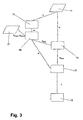
- FIG. 3 A development of the invention, which provides a more accurate control of the braking effect is in FIG. 3 schematically shown:
- the pivot angle ⁇ of the drawbar 7 is determined in the same manner as described above in the measured value detecting device 14.
- a time measurement is carried out and thus the angular velocity ⁇ of the drawbar 7 is calculated from the swivel angle ⁇ .
- the desired braking range is determined as a function of the sign of the angular velocity ⁇ and the stored in the storage device 21 angle ⁇ end I or ⁇ End III , where the range I or III begins, selected and transmitted to the subtraction device 15, where on the already described manner of remaining to the braking area residual angle ⁇ rest bestimm t is.
- the residual angle ⁇ residual is divided in the division device 17 by the angular velocity ⁇ determined in the computing device 19. This makes it possible to calculate the time t until reaching the braking range much more accurately than with the above-described method. In particular, a constant adjustment of the braking effect to a change in the angular velocity ⁇ can be made.
- the direction of the tiller movement (i.e., the sign of the angular velocity) flows in particular by determining whether the residual travel that the tiller has to travel until reaching a brake range is to be calculated in the range of I or III.
- the direction of the pivoting movement to the effect that the braking effect is chosen differently for movements of the drawbar to an approximately vertical end position than when moving to an approximately horizontal end position.
- the end point of the swivel angle ⁇ can also be used as the input value for the subtraction device 15. Then, when the brake area is reached, the truck will still have a residual speed, which in the interaction of parking brake device and Service brake device is dismantled. The resulting jerk makes it clear to the operator that the parking brake device is active, which may be desired in special cases.
Landscapes
- Engineering & Computer Science (AREA)
- Transportation (AREA)
- Mechanical Engineering (AREA)
- Chemical & Material Sciences (AREA)
- Combustion & Propulsion (AREA)
- Structural Engineering (AREA)
- Civil Engineering (AREA)
- Life Sciences & Earth Sciences (AREA)
- Geology (AREA)
- Regulating Braking Force (AREA)
- Braking Arrangements (AREA)
Applications Claiming Priority (1)
| Application Number | Priority Date | Filing Date | Title |
|---|---|---|---|
| DE102006061069A DE102006061069A1 (de) | 2006-12-22 | 2006-12-22 | Deichselgeführtes Flurförderzeug |
Publications (2)
| Publication Number | Publication Date |
|---|---|
| EP1935838A1 true EP1935838A1 (fr) | 2008-06-25 |
| EP1935838B1 EP1935838B1 (fr) | 2012-02-29 |
Family
ID=39168057
Family Applications (1)
| Application Number | Title | Priority Date | Filing Date |
|---|---|---|---|
| EP07023263A Not-in-force EP1935838B1 (fr) | 2006-12-22 | 2007-11-30 | Chariot de manutention commandé par timon |
Country Status (3)
| Country | Link |
|---|---|
| EP (1) | EP1935838B1 (fr) |
| AT (1) | ATE547376T1 (fr) |
| DE (1) | DE102006061069A1 (fr) |
Cited By (3)
| Publication number | Priority date | Publication date | Assignee | Title |
|---|---|---|---|---|
| EP2511145A3 (fr) * | 2011-04-12 | 2013-09-04 | Jungheinrich Aktiengesellschaft | Chariot de manutention avec frein d'arrêt et procédé de réglage d'un moment d'arrêt du chariot de manutention |
| EP2647557A3 (fr) * | 2012-04-02 | 2015-03-25 | Jungheinrich Aktiengesellschaft | Chariot de manutention avec un timon pivotant autour d'un axe horizontal |
| CN112793635A (zh) * | 2021-01-30 | 2021-05-14 | 上海电机学院 | 一种防碰撞损坏的锂离子电池转运装置 |
Families Citing this family (5)
| Publication number | Priority date | Publication date | Assignee | Title |
|---|---|---|---|---|
| DE102008012626A1 (de) * | 2008-02-28 | 2009-09-03 | GEMÜ Gebr. Müller Apparatebau GmbH & Co. KG | Handhubwagen |
| DE102009004042A1 (de) * | 2009-01-08 | 2010-07-15 | Allconsult Ltd. | Flurförderzeug |
| DE102011014768A1 (de) | 2011-03-23 | 2012-09-27 | Jungheinrich Aktiengesellschaft | Deichselgeführtes Förderzeug |
| DE102011016635A1 (de) * | 2011-04-09 | 2012-10-11 | Jungheinrich Aktiengesellschaft | Betätigungselement für ein Flurförderzeug |
| CN116061941A (zh) | 2018-09-13 | 2023-05-05 | 克朗设备公司 | 基于计算负载的工业车辆最大车辆速度控制系统和方法 |
Citations (5)
| Publication number | Priority date | Publication date | Assignee | Title |
|---|---|---|---|---|
| US2645297A (en) * | 1948-05-07 | 1953-07-14 | Wennberg Olov Carl Gustav | Handle control for electrically driven lift trucks |
| US3791474A (en) * | 1971-04-02 | 1974-02-12 | Crown Controls Corp | Motion selector device for a lift truck |
| EP1013602A1 (fr) | 1998-12-23 | 2000-06-28 | Crown Gabelstapler GmbH | Véhicule chargeur-élévateur |
| EP1264759A1 (fr) | 2001-06-08 | 2002-12-11 | Still & Saxby S.à.r.l. | Chariot de manutention guidé par timon |
| US20030029647A1 (en) | 2001-08-09 | 2003-02-13 | Trego Allen T. | Supplemental walk along control for walkie/rider pallet trucks |
-
2006
- 2006-12-22 DE DE102006061069A patent/DE102006061069A1/de not_active Withdrawn
-
2007
- 2007-11-30 EP EP07023263A patent/EP1935838B1/fr not_active Not-in-force
- 2007-11-30 AT AT07023263T patent/ATE547376T1/de active
Patent Citations (5)
| Publication number | Priority date | Publication date | Assignee | Title |
|---|---|---|---|---|
| US2645297A (en) * | 1948-05-07 | 1953-07-14 | Wennberg Olov Carl Gustav | Handle control for electrically driven lift trucks |
| US3791474A (en) * | 1971-04-02 | 1974-02-12 | Crown Controls Corp | Motion selector device for a lift truck |
| EP1013602A1 (fr) | 1998-12-23 | 2000-06-28 | Crown Gabelstapler GmbH | Véhicule chargeur-élévateur |
| EP1264759A1 (fr) | 2001-06-08 | 2002-12-11 | Still & Saxby S.à.r.l. | Chariot de manutention guidé par timon |
| US20030029647A1 (en) | 2001-08-09 | 2003-02-13 | Trego Allen T. | Supplemental walk along control for walkie/rider pallet trucks |
Cited By (3)
| Publication number | Priority date | Publication date | Assignee | Title |
|---|---|---|---|---|
| EP2511145A3 (fr) * | 2011-04-12 | 2013-09-04 | Jungheinrich Aktiengesellschaft | Chariot de manutention avec frein d'arrêt et procédé de réglage d'un moment d'arrêt du chariot de manutention |
| EP2647557A3 (fr) * | 2012-04-02 | 2015-03-25 | Jungheinrich Aktiengesellschaft | Chariot de manutention avec un timon pivotant autour d'un axe horizontal |
| CN112793635A (zh) * | 2021-01-30 | 2021-05-14 | 上海电机学院 | 一种防碰撞损坏的锂离子电池转运装置 |
Also Published As
| Publication number | Publication date |
|---|---|
| ATE547376T1 (de) | 2012-03-15 |
| EP1935838B1 (fr) | 2012-02-29 |
| DE102006061069A1 (de) | 2008-06-26 |
Similar Documents
| Publication | Publication Date | Title |
|---|---|---|
| EP1935838B1 (fr) | Chariot de manutention commandé par timon | |
| DE69722977T2 (de) | Antriebsystem für einen Personenaufzug mit vertikalem Mast | |
| EP0466065B1 (fr) | Véhicule de transport de charges | |
| EP1985576B1 (fr) | Procédé et dispositif destinés à empêcher le basculement d'un dispositif d'empilage à contrepoids | |
| DE3316129A1 (de) | Vorrichtung zum anheben und absenken einer luftleitplatte | |
| DE3211958A1 (de) | Steuervorrichtung fuer eine lade- und entladungeeinrichtung eines gabelstapels | |
| DE102014202230A1 (de) | Verfahren und Vorrichtung zum Verhindern eines Kippens eines lenkbaren Fahrzeugs | |
| EP1925513B1 (fr) | Chariot de manutention doté d'un dispositif d'extraction latérale d'une unité d'alimentation en énergie | |
| DE112011103062T5 (de) | Motorsteuerung für Gabelstapler | |
| DE10127905A1 (de) | Deichselgelenktes Flurförderzeug | |
| EP2899318A1 (fr) | Engin automobile de construction routière, en particulier compresseur et procédé de conduite d'un engin de construction routière | |
| EP0465838A1 (fr) | Véhicule porte-charge avec securité contre le basculement | |
| DE102018010151A1 (de) | Verfahren zur Höhenregulierung eines Seitenschilds einer Bodenfräsmaschine und Bodenfräsmaschine | |
| EP2918483B1 (fr) | Procédé de manoeuvre d'une remorque à essieu tandem au moyen d'un dispositif de manoeuvre et dispositif de manoeuvre | |
| DE102016106459A1 (de) | Arbeitsfahrzeug mit Knick-Gelenk-Lenkung und lastabhängiger Lenkwinkelbegrenzung | |
| EP0382231B1 (fr) | Procédé et disposition pour la limitation de la zone de déplacement d'une grue | |
| EP1700767A2 (fr) | Chariot de manutention guidé par timon | |
| EP3214035B1 (fr) | Procédé de fonctionnement d'un chariot de manutention | |
| EP3115332B1 (fr) | Procede de commande d'un chariot de manutention | |
| EP1927516B1 (fr) | Chariot de manutention doté d'un dispositif de maintien de conducteur pouvant être déplacé devant un dispositif de réglage | |
| EP2072364B1 (fr) | Dispositif destiné à la prise en charge semi-automatique d'un processus de stationnement d'un véhicule | |
| DE19607976C2 (de) | Fahrtgeber für ein von einem Motor angetriebenes Mitgeh-Flurförderzeug | |
| EP1710148B1 (fr) | Système de direction pour un chariot de manutention | |
| DE2946931C2 (fr) | ||
| DE102015115825A1 (de) | Verfahren zur Steuerung eines Flurförderzeugs |
Legal Events
| Date | Code | Title | Description |
|---|---|---|---|
| PUAI | Public reference made under article 153(3) epc to a published international application that has entered the european phase |
Free format text: ORIGINAL CODE: 0009012 |
|
| AK | Designated contracting states |
Kind code of ref document: A1 Designated state(s): AT BE BG CH CY CZ DE DK EE ES FI FR GB GR HU IE IS IT LI LT LU LV MC MT NL PL PT RO SE SI SK TR |
|
| AX | Request for extension of the european patent |
Extension state: AL BA HR MK RS |
|
| RIN1 | Information on inventor provided before grant (corrected) |
Inventor name: FERREIRA, PAULO Inventor name: BROUART, FRANCOIS |
|
| 17P | Request for examination filed |
Effective date: 20081031 |
|
| 17Q | First examination report despatched |
Effective date: 20081218 |
|
| AKX | Designation fees paid |
Designated state(s): AT BE BG CH CY CZ DE DK EE ES FI FR GB GR HU IE IS IT LI LT LU LV MC MT NL PL PT RO SE SI SK TR |
|
| GRAP | Despatch of communication of intention to grant a patent |
Free format text: ORIGINAL CODE: EPIDOSNIGR1 |
|
| RIC1 | Information provided on ipc code assigned before grant |
Ipc: B60T 7/10 20060101ALI20110930BHEP Ipc: B62D 51/04 20060101ALI20110930BHEP Ipc: B62D 51/00 20060101ALI20110930BHEP Ipc: B66F 9/24 20060101AFI20110930BHEP |
|
| GRAS | Grant fee paid |
Free format text: ORIGINAL CODE: EPIDOSNIGR3 |
|
| GRAA | (expected) grant |
Free format text: ORIGINAL CODE: 0009210 |
|
| AK | Designated contracting states |
Kind code of ref document: B1 Designated state(s): AT BE BG CH CY CZ DE DK EE ES FI FR GB GR HU IE IS IT LI LT LU LV MC MT NL PL PT RO SE SI SK TR |
|
| REG | Reference to a national code |
Ref country code: GB Ref legal event code: FG4D Free format text: NOT ENGLISH Ref country code: CH Ref legal event code: EP |
|
| REG | Reference to a national code |
Ref country code: AT Ref legal event code: REF Ref document number: 547376 Country of ref document: AT Kind code of ref document: T Effective date: 20120315 |
|
| REG | Reference to a national code |
Ref country code: IE Ref legal event code: FG4D Free format text: LANGUAGE OF EP DOCUMENT: GERMAN |
|
| REG | Reference to a national code |
Ref country code: DE Ref legal event code: R096 Ref document number: 502007009360 Country of ref document: DE Effective date: 20120426 |
|
| REG | Reference to a national code |
Ref country code: SE Ref legal event code: TRGR |
|
| REG | Reference to a national code |
Ref country code: NL Ref legal event code: VDEP Effective date: 20120229 |
|
| LTIE | Lt: invalidation of european patent or patent extension |
Effective date: 20120229 |
|
| PG25 | Lapsed in a contracting state [announced via postgrant information from national office to epo] |
Ref country code: NL Free format text: LAPSE BECAUSE OF FAILURE TO SUBMIT A TRANSLATION OF THE DESCRIPTION OR TO PAY THE FEE WITHIN THE PRESCRIBED TIME-LIMIT Effective date: 20120229 Ref country code: IS Free format text: LAPSE BECAUSE OF FAILURE TO SUBMIT A TRANSLATION OF THE DESCRIPTION OR TO PAY THE FEE WITHIN THE PRESCRIBED TIME-LIMIT Effective date: 20120629 Ref country code: LT Free format text: LAPSE BECAUSE OF FAILURE TO SUBMIT A TRANSLATION OF THE DESCRIPTION OR TO PAY THE FEE WITHIN THE PRESCRIBED TIME-LIMIT Effective date: 20120229 |
|
| PG25 | Lapsed in a contracting state [announced via postgrant information from national office to epo] |
Ref country code: PT Free format text: LAPSE BECAUSE OF FAILURE TO SUBMIT A TRANSLATION OF THE DESCRIPTION OR TO PAY THE FEE WITHIN THE PRESCRIBED TIME-LIMIT Effective date: 20120629 Ref country code: FI Free format text: LAPSE BECAUSE OF FAILURE TO SUBMIT A TRANSLATION OF THE DESCRIPTION OR TO PAY THE FEE WITHIN THE PRESCRIBED TIME-LIMIT Effective date: 20120229 Ref country code: GR Free format text: LAPSE BECAUSE OF FAILURE TO SUBMIT A TRANSLATION OF THE DESCRIPTION OR TO PAY THE FEE WITHIN THE PRESCRIBED TIME-LIMIT Effective date: 20120530 Ref country code: LV Free format text: LAPSE BECAUSE OF FAILURE TO SUBMIT A TRANSLATION OF THE DESCRIPTION OR TO PAY THE FEE WITHIN THE PRESCRIBED TIME-LIMIT Effective date: 20120229 |
|
| REG | Reference to a national code |
Ref country code: IE Ref legal event code: FD4D |
|
| PG25 | Lapsed in a contracting state [announced via postgrant information from national office to epo] |
Ref country code: CY Free format text: LAPSE BECAUSE OF FAILURE TO SUBMIT A TRANSLATION OF THE DESCRIPTION OR TO PAY THE FEE WITHIN THE PRESCRIBED TIME-LIMIT Effective date: 20120229 |
|
| PG25 | Lapsed in a contracting state [announced via postgrant information from national office to epo] |
Ref country code: PL Free format text: LAPSE BECAUSE OF FAILURE TO SUBMIT A TRANSLATION OF THE DESCRIPTION OR TO PAY THE FEE WITHIN THE PRESCRIBED TIME-LIMIT Effective date: 20120229 Ref country code: DK Free format text: LAPSE BECAUSE OF FAILURE TO SUBMIT A TRANSLATION OF THE DESCRIPTION OR TO PAY THE FEE WITHIN THE PRESCRIBED TIME-LIMIT Effective date: 20120229 Ref country code: EE Free format text: LAPSE BECAUSE OF FAILURE TO SUBMIT A TRANSLATION OF THE DESCRIPTION OR TO PAY THE FEE WITHIN THE PRESCRIBED TIME-LIMIT Effective date: 20120229 Ref country code: CZ Free format text: LAPSE BECAUSE OF FAILURE TO SUBMIT A TRANSLATION OF THE DESCRIPTION OR TO PAY THE FEE WITHIN THE PRESCRIBED TIME-LIMIT Effective date: 20120229 Ref country code: SI Free format text: LAPSE BECAUSE OF FAILURE TO SUBMIT A TRANSLATION OF THE DESCRIPTION OR TO PAY THE FEE WITHIN THE PRESCRIBED TIME-LIMIT Effective date: 20120229 Ref country code: IE Free format text: LAPSE BECAUSE OF FAILURE TO SUBMIT A TRANSLATION OF THE DESCRIPTION OR TO PAY THE FEE WITHIN THE PRESCRIBED TIME-LIMIT Effective date: 20120229 Ref country code: RO Free format text: LAPSE BECAUSE OF FAILURE TO SUBMIT A TRANSLATION OF THE DESCRIPTION OR TO PAY THE FEE WITHIN THE PRESCRIBED TIME-LIMIT Effective date: 20120229 |
|
| PG25 | Lapsed in a contracting state [announced via postgrant information from national office to epo] |
Ref country code: SK Free format text: LAPSE BECAUSE OF FAILURE TO SUBMIT A TRANSLATION OF THE DESCRIPTION OR TO PAY THE FEE WITHIN THE PRESCRIBED TIME-LIMIT Effective date: 20120229 |
|
| PLBE | No opposition filed within time limit |
Free format text: ORIGINAL CODE: 0009261 |
|
| STAA | Information on the status of an ep patent application or granted ep patent |
Free format text: STATUS: NO OPPOSITION FILED WITHIN TIME LIMIT |
|
| 26N | No opposition filed |
Effective date: 20121130 |
|
| REG | Reference to a national code |
Ref country code: DE Ref legal event code: R097 Ref document number: 502007009360 Country of ref document: DE Effective date: 20121130 |
|
| PG25 | Lapsed in a contracting state [announced via postgrant information from national office to epo] |
Ref country code: ES Free format text: LAPSE BECAUSE OF FAILURE TO SUBMIT A TRANSLATION OF THE DESCRIPTION OR TO PAY THE FEE WITHIN THE PRESCRIBED TIME-LIMIT Effective date: 20120609 |
|
| BERE | Be: lapsed |
Owner name: STILL SAS Effective date: 20121130 |
|
| REG | Reference to a national code |
Ref country code: CH Ref legal event code: PL |
|
| GBPC | Gb: european patent ceased through non-payment of renewal fee |
Effective date: 20121130 |
|
| PG25 | Lapsed in a contracting state [announced via postgrant information from national office to epo] |
Ref country code: BG Free format text: LAPSE BECAUSE OF FAILURE TO SUBMIT A TRANSLATION OF THE DESCRIPTION OR TO PAY THE FEE WITHIN THE PRESCRIBED TIME-LIMIT Effective date: 20120529 Ref country code: LI Free format text: LAPSE BECAUSE OF NON-PAYMENT OF DUE FEES Effective date: 20121130 Ref country code: CH Free format text: LAPSE BECAUSE OF NON-PAYMENT OF DUE FEES Effective date: 20121130 |
|
| PG25 | Lapsed in a contracting state [announced via postgrant information from national office to epo] |
Ref country code: BE Free format text: LAPSE BECAUSE OF NON-PAYMENT OF DUE FEES Effective date: 20121130 |
|
| PG25 | Lapsed in a contracting state [announced via postgrant information from national office to epo] |
Ref country code: GB Free format text: LAPSE BECAUSE OF NON-PAYMENT OF DUE FEES Effective date: 20121130 Ref country code: MT Free format text: LAPSE BECAUSE OF FAILURE TO SUBMIT A TRANSLATION OF THE DESCRIPTION OR TO PAY THE FEE WITHIN THE PRESCRIBED TIME-LIMIT Effective date: 20120229 |
|
| REG | Reference to a national code |
Ref country code: AT Ref legal event code: MM01 Ref document number: 547376 Country of ref document: AT Kind code of ref document: T Effective date: 20121130 |
|
| PG25 | Lapsed in a contracting state [announced via postgrant information from national office to epo] |
Ref country code: AT Free format text: LAPSE BECAUSE OF NON-PAYMENT OF DUE FEES Effective date: 20121130 |
|
| REG | Reference to a national code |
Ref country code: DE Ref legal event code: R082 Ref document number: 502007009360 Country of ref document: DE Representative=s name: GEIRHOS & WALLER PATENT- UND RECHTSANWAELTE, DE |
|
| REG | Reference to a national code |
Ref country code: DE Ref legal event code: R082 Ref document number: 502007009360 Country of ref document: DE Representative=s name: PATENTSHIP PATENTANWALTSGESELLSCHAFT MBH, DE Effective date: 20140225 Ref country code: DE Ref legal event code: R081 Ref document number: 502007009360 Country of ref document: DE Owner name: OM CARRELLI ELEVATORI S.P.A., IT Free format text: FORMER OWNER: STILL SAS, MARNE LA VALLEE, FR Effective date: 20140225 Ref country code: DE Ref legal event code: R082 Ref document number: 502007009360 Country of ref document: DE Representative=s name: GEIRHOS & WALLER PATENT- UND RECHTSANWAELTE, DE Effective date: 20140225 Ref country code: DE Ref legal event code: R081 Ref document number: 502007009360 Country of ref document: DE Owner name: OM CARRELLI ELEVATORI S.P.A., IT Free format text: FORMER OWNER: STILL SAS, MARNE LA VALLEE, CEDEX 4, FR Effective date: 20140225 |
|
| PG25 | Lapsed in a contracting state [announced via postgrant information from national office to epo] |
Ref country code: MC Free format text: LAPSE BECAUSE OF NON-PAYMENT OF DUE FEES Effective date: 20121130 Ref country code: TR Free format text: LAPSE BECAUSE OF FAILURE TO SUBMIT A TRANSLATION OF THE DESCRIPTION OR TO PAY THE FEE WITHIN THE PRESCRIBED TIME-LIMIT Effective date: 20120229 |
|
| PG25 | Lapsed in a contracting state [announced via postgrant information from national office to epo] |
Ref country code: LU Free format text: LAPSE BECAUSE OF NON-PAYMENT OF DUE FEES Effective date: 20121130 |
|
| PG25 | Lapsed in a contracting state [announced via postgrant information from national office to epo] |
Ref country code: HU Free format text: LAPSE BECAUSE OF FAILURE TO SUBMIT A TRANSLATION OF THE DESCRIPTION OR TO PAY THE FEE WITHIN THE PRESCRIBED TIME-LIMIT Effective date: 20071130 |
|
| REG | Reference to a national code |
Ref country code: FR Ref legal event code: TP Owner name: OM CARRELLI ELEVATORI S.P.A., IT Effective date: 20150218 |
|
| REG | Reference to a national code |
Ref country code: FR Ref legal event code: PLFP Year of fee payment: 9 |
|
| REG | Reference to a national code |
Ref country code: FR Ref legal event code: PLFP Year of fee payment: 10 |
|
| REG | Reference to a national code |
Ref country code: DE Ref legal event code: R082 Ref document number: 502007009360 Country of ref document: DE Representative=s name: PATENTSHIP PATENTANWALTSGESELLSCHAFT MBH, DE |
|
| REG | Reference to a national code |
Ref country code: DE Ref legal event code: R082 Ref document number: 502007009360 Country of ref document: DE Representative=s name: PATENTSHIP PATENTANWALTSGESELLSCHAFT MBH, DE |
|
| REG | Reference to a national code |
Ref country code: FR Ref legal event code: PLFP Year of fee payment: 11 |
|
| PGFP | Annual fee paid to national office [announced via postgrant information from national office to epo] |
Ref country code: DE Payment date: 20171124 Year of fee payment: 11 Ref country code: FR Payment date: 20171124 Year of fee payment: 11 |
|
| PGFP | Annual fee paid to national office [announced via postgrant information from national office to epo] |
Ref country code: SE Payment date: 20171124 Year of fee payment: 11 Ref country code: IT Payment date: 20171122 Year of fee payment: 11 |
|
| REG | Reference to a national code |
Ref country code: DE Ref legal event code: R119 Ref document number: 502007009360 Country of ref document: DE |
|
| REG | Reference to a national code |
Ref country code: SE Ref legal event code: EUG |
|
| PG25 | Lapsed in a contracting state [announced via postgrant information from national office to epo] |
Ref country code: SE Free format text: LAPSE BECAUSE OF NON-PAYMENT OF DUE FEES Effective date: 20181201 |
|
| PG25 | Lapsed in a contracting state [announced via postgrant information from national office to epo] |
Ref country code: DE Free format text: LAPSE BECAUSE OF NON-PAYMENT OF DUE FEES Effective date: 20190601 Ref country code: FR Free format text: LAPSE BECAUSE OF NON-PAYMENT OF DUE FEES Effective date: 20181130 Ref country code: IT Free format text: LAPSE BECAUSE OF NON-PAYMENT OF DUE FEES Effective date: 20181130 |