EP1935838A1 - Industrial truck lead by a drawbar - Google Patents
Industrial truck lead by a drawbar Download PDFInfo
- Publication number
- EP1935838A1 EP1935838A1 EP07023263A EP07023263A EP1935838A1 EP 1935838 A1 EP1935838 A1 EP 1935838A1 EP 07023263 A EP07023263 A EP 07023263A EP 07023263 A EP07023263 A EP 07023263A EP 1935838 A1 EP1935838 A1 EP 1935838A1
- Authority
- EP
- European Patent Office
- Prior art keywords
- drawbar
- brake device
- swivel
- truck
- service brake
- Prior art date
- Legal status (The legal status is an assumption and is not a legal conclusion. Google has not performed a legal analysis and makes no representation as to the accuracy of the status listed.)
- Granted
Links
Images


Classifications
-
- B—PERFORMING OPERATIONS; TRANSPORTING
- B66—HOISTING; LIFTING; HAULING
- B66F—HOISTING, LIFTING, HAULING OR PUSHING, NOT OTHERWISE PROVIDED FOR, e.g. DEVICES WHICH APPLY A LIFTING OR PUSHING FORCE DIRECTLY TO THE SURFACE OF A LOAD
- B66F9/00—Devices for lifting or lowering bulky or heavy goods for loading or unloading purposes
- B66F9/06—Devices for lifting or lowering bulky or heavy goods for loading or unloading purposes movable, with their loads, on wheels or the like, e.g. fork-lift trucks
- B66F9/075—Constructional features or details
- B66F9/20—Means for actuating or controlling masts, platforms, or forks
- B66F9/24—Electrical devices or systems
-
- B—PERFORMING OPERATIONS; TRANSPORTING
- B60—VEHICLES IN GENERAL
- B60T—VEHICLE BRAKE CONTROL SYSTEMS OR PARTS THEREOF; BRAKE CONTROL SYSTEMS OR PARTS THEREOF, IN GENERAL; ARRANGEMENT OF BRAKING ELEMENTS ON VEHICLES IN GENERAL; PORTABLE DEVICES FOR PREVENTING UNWANTED MOVEMENT OF VEHICLES; VEHICLE MODIFICATIONS TO FACILITATE COOLING OF BRAKES
- B60T7/00—Brake-action initiating means
- B60T7/02—Brake-action initiating means for personal initiation
- B60T7/08—Brake-action initiating means for personal initiation hand actuated
- B60T7/10—Disposition of hand control
- B60T7/102—Disposition of hand control by means of a tilting lever
-
- B—PERFORMING OPERATIONS; TRANSPORTING
- B62—LAND VEHICLES FOR TRAVELLING OTHERWISE THAN ON RAILS
- B62D—MOTOR VEHICLES; TRAILERS
- B62D51/00—Motor vehicles characterised by the driver not being seated
- B62D51/001—Motor vehicles characterised by the driver not being seated characterised by the vehicle control device
-
- B—PERFORMING OPERATIONS; TRANSPORTING
- B62—LAND VEHICLES FOR TRAVELLING OTHERWISE THAN ON RAILS
- B62B—HAND-PROPELLED VEHICLES, e.g. HAND CARTS OR PERAMBULATORS; SLEDGES
- B62B5/00—Accessories or details specially adapted for hand carts
- B62B5/06—Hand moving equipment, e.g. handle bars
- B62B5/063—Hand moving equipment, e.g. handle bars for low-lift hand trucks
Definitions
- the invention relates to a truck with a pivotable about a horizontal axis steering handle, a service brake device and means for continuously detecting the pivot angle of the steering arm about the horizontal axis.
- Tiller-guided industrial trucks for example, high or low pallet trucks and order pickers, have as a steering element on a drawbar, with the pivoting about a vertical axis the vehicle is steered, while the control of direction of travel and speed is usually made via wing switches in the tiller head.
- the drawbar can also be pivoted from an approximately vertical end position about a horizontal axis in an approximately horizontal end position to adapt the drawbar to the size of the user and to either have a large lever arm available, which reduces the effort when steering the vehicle, or with a raised drawbar to reduce the space requirement of the vehicle, especially when maneuvering.
- the tiller is usually coupled to a parking brake device of the vehicle such that braking is triggered when the tiller is in the vicinity of the approximately vertical end position, i. in the so-called upper brake area, is located. Furthermore, depending on the design of the vehicle when approaching the approximately horizontal end position of the drawbar, i. in a so-called lower braking range, also a braking be triggered. Therefore, to bring the vehicle to a standstill, the operator only needs to bring the tiller into one of the braking areas to deploy the parking brake device.
- the drawbar is provided with a spring mechanism that automatically brings them into the approximately vertical end position and holds there. Lets the operator while driving from the vertical end position swung drawbar los, this is pivoted upward and automatically initiated a braking. This reliably prevents the vehicle from getting out of control.
- the parking brake device also acts as parking or holding brake, which secures the vehicle at a standstill.
- the parking brake device although a good effect, but is poorly dosed and subject to high wear. A prudent operator will therefore bring the vehicle to a standstill in normal operation by decelerating over the traction motor acting as a service brake device by bringing the wing switches to control the direction and speed of travel to zero or in the opposite direction.
- tiller-guided industrial trucks are often operated by inexperienced operators - in contrast to counterbalanced forklift trucks, for example. It is often difficult for these operators to correctly assess the driving behavior of the vehicle and to make the braking so that it comes to a standstill in time. This results in a significant safety risk, which is even higher for vehicles with fold-out or permanently installed driver's platform due to the often higher driving speeds, in contrast to pure pedestrian vehicles.
- the invention is therefore based on the object, an industrial truck with a pivotable about a horizontal axis steering handle, a service brake device and To provide means for continuously detecting the pivoting angle of the steering arm about the horizontal axis, with the simple and safe braking is made possible even for inexperienced operators.
- the service brake device is designed such that the braking effect of the service brake device in dependence on the pivot angle and / or the pivoting speed and / or the pivotal acceleration of the drawbar about the horizontal axis is adjustable.
- the angular position of the drawbar allows, as well as their acceleration and speed during pivoting conclusions about the operating condition of the vehicle and thus to the desired braking effect.
- a rapid braking is desired.
- a swivel angle where there is an increased danger to the operator - for example, when the drawbar is near the upper brake area and therefore the operator is likely to be near the vehicle - quicker braking is needed rather than at a position where no immediate danger threatens.
- the truck has at least one traction motor, in particular at least one electric traction motor, and the traction motor is designed as a service brake device. This does not require an independent service brake device.
- electric traction motors offer good metering of the braking effect, are virtually wear-free and make it possible to recover energy during braking.
- the service brake device is designed such that the braking effect of the service brake device as a function of the swivel angle and / or the swivel speed and / or the swivel acceleration of the drawbar about the horizontal axis is approximately infinitely adjustable.
- a particularly fine dosing of the braking effect is achieved, which makes it possible to optimally adapt the braking process to external conditions.
- a gradation is considered to be virtually infinitely variable, which is so fine that the difference between two levels is no longer clearly perceptible to the average operator.
- the service brake device is designed such that the braking effect of the service brake device approximately proportional to the swivel angle and / or the swivel speed and / or the pivot acceleration of the drawbar adjustable.
- the braking effect be chosen to be greater than a slow lifting, in which the operator probably wants to roll out the vehicle, then to activate the parking brake device as a holding brake when the breakpoint.
- the braking effect can with decreasing swivel angle, i. Approaching the vertical end position, increased to increase safety with increasingly closer to the vehicle driver.
- the service brake device is designed such that the size of the braking effect is adjustable so that when reaching at least one end position and / or a braking range, preferably the upper end position or the upper braking range of the drawbar the truck is almost stationary.
- the parking brake device is no longer needed to decelerate the vehicle, which reduces their wear.
- this can, if their effect is needed only at a standstill, be dimensioned smaller than in a vehicle according to the prior art.
- the dependence of the braking effect of the service brake device on the swivel angle and / or the swivel speed and / or the swivel acceleration of the drawbar about the horizontal axis in the form of a characteristic and / or a characteristic field is predetermined.
- a characteristic and / or a map allow a particularly accurate coordination of the braking behavior on the movement of the drawbar.
- a characteristic diagram which specifies the braking effect as a function of a plurality of variables, for example the drawbar position and speed, this is possible very precisely.
- the input variables used in the characteristic field comprise at least one variable influencing the braking behavior of the industrial truck, in particular one of the variables enumerated below: pivoting angle of the drawbar, pivoting speed of the drawbar, swinging acceleration of the drawbar, Driving direction of the vehicle, driving speed of the vehicle, driving acceleration of the vehicle, steering angle, weight of the vehicle and / or the load.
- the means for continuous detection of the swivel angle and / or the swivel speed and / or the swivel acceleration of the drawbar about the horizontal axis comprise at least one potentiometer.
- Potentiometers are simple and compact components that can be easily positioned in the area of the swivel axis and whose signal can be easily evaluated and converted into stepless angle information.
- a lift truck 1 is shown with a fork-shaped load-carrying means 2.
- the lift truck 1 consists of a drive part 3 with a drive wheel 4 and a support wheel, not shown here, and a load part 5 with the load receiving means 2 and rollers 6.
- a driving and a lifting drive are housed, which are not shown here .
- the vehicle 1 is steered by pivoting the drawbar 7 about a vertical axis 8 and control elements 9, 9 a, which are arranged on a tiller head 10, the vehicle functions such as direction and speed and lifting and lowering of the lifting device. 2 controlled.
- the drawbar 7 is movably mounted about a horizontal pivot axis 11.
- the drawbar 7 can be adapted to the size of the operator and when maneuvering in a confined space by raising the drawbar 7, the space requirement of the lift truck 1 can be reduced.
- a arranged in the pole base 12, not shown here pivot joint is coupled to a potentiometer, also not shown, which changes its resistance as a function of the pivot angle ⁇ of the drawbar 7 about the horizontal pivot axis 11. This change is detected in the controller 13 of the lift truck 1 and calculates the swing angle ⁇ .
- the lift truck 1 is not only driven and steered via the drive wheel 4, but also braked.
- electric traction drive motor is provided as a service brake device and also not shown independent parking brake device.
- the parking brake device works according to electromagnetic principle and is activated depending on the drawbar position.
- the pivoting range of the drawbar 7 is divided into three areas: If the drawbar in the area I or III, the parking brake device is automatically activated with full braking force. In area II normal driving is possible and the parking brake device solved.
- a spring mechanism not shown here, is also arranged, which brings the drawbar 7 automatically in an approximately vertical position or holds there. This has the consequence that, as soon as the operator releases the drawbar 7, it moves into the area I and the truck 1 is automatically braked by activating the parking brake device. In area II, only the service brake device can be activated. This is done by either releasing the wing switches 9a at which the vehicle speed and direction are adjusted to obtain a small braking effect or deflecting them in the opposite direction to obtain a large braking effect.
- a target speed is given by the position of the wing switch 9a and the electric control 13 of the drive motor controls it so that the target speed is reached in a predetermined period, ie it is internally set a speed ramp and the moment of Driving motor controlled so that the vehicle 1 behaves according to this ramp.
- the lifting carriage 1 according to the invention is in braking mode, ie if the wing switch 9a is deflected in the neutral position or in the direction opposite to the instantaneous direction of travel, the braking effect of the traveling motor is set as a function of the position of the drawbar 7 or the variables derivable therefrom.
- FIG. 2 A simple embodiment of the invention is shown schematically in FIG. 2
- the instantaneous swivel angle ⁇ of the drawbar 7 is determined in a measured value detection device 14 from the resistance of the pole arranged in the drawbar 12 and in a subtraction device 15, the difference calculated in a storage device 16 angle ⁇ end I of the beginning of the range I of the drawbar 7 calculated ,
- This difference indicates the residual angle ⁇ residual to be traveled down to the braking region, which is divided in a divider device 17 by an assumed angular velocity ⁇ of the drawbar 7 stored in a storage device 18. This results in the time t within which the vehicle 1 must be brought to a standstill.
- the deceleration ramp ie the relationship between vehicle speed and time, set for the traction motor and starting from this, the torque of the electric drive motor so controlled that the truck 1 comes to a standstill when the drawbar 7 with the assumed Speed is moved and reaches the desired braking range.
- the assumed angular velocity of the drawbar 7 in the exemplary embodiment is an empirically determined quantity which represents the average speed determined by different operators for rapid movement of the drawbar 7 from a central position to the end point, but other values are also possible, for example the speed that sets when the drawbar 7 is brought by means of the spring mechanism in the pole base 12 in an upright position.
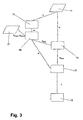
- FIG. 3 A development of the invention, which provides a more accurate control of the braking effect is in FIG. 3 schematically shown:
- the pivot angle ⁇ of the drawbar 7 is determined in the same manner as described above in the measured value detecting device 14.
- a time measurement is carried out and thus the angular velocity ⁇ of the drawbar 7 is calculated from the swivel angle ⁇ .
- the desired braking range is determined as a function of the sign of the angular velocity ⁇ and the stored in the storage device 21 angle ⁇ end I or ⁇ End III , where the range I or III begins, selected and transmitted to the subtraction device 15, where on the already described manner of remaining to the braking area residual angle ⁇ rest bestimm t is.
- the residual angle ⁇ residual is divided in the division device 17 by the angular velocity ⁇ determined in the computing device 19. This makes it possible to calculate the time t until reaching the braking range much more accurately than with the above-described method. In particular, a constant adjustment of the braking effect to a change in the angular velocity ⁇ can be made.
- the direction of the tiller movement (i.e., the sign of the angular velocity) flows in particular by determining whether the residual travel that the tiller has to travel until reaching a brake range is to be calculated in the range of I or III.
- the direction of the pivoting movement to the effect that the braking effect is chosen differently for movements of the drawbar to an approximately vertical end position than when moving to an approximately horizontal end position.
- the end point of the swivel angle ⁇ can also be used as the input value for the subtraction device 15. Then, when the brake area is reached, the truck will still have a residual speed, which in the interaction of parking brake device and Service brake device is dismantled. The resulting jerk makes it clear to the operator that the parking brake device is active, which may be desired in special cases.
Abstract
Description
Die Erfindung betrifft ein Flurförderzeug mit einer um eine horizontale Achse schwenkbaren Lenkdeichsel, einer Betriebsbremsvorrichtung und Mitteln zur stufenlosen Erfassung des Schwenkwinkels der Lenkdeichsel um die horizontale Achse.The invention relates to a truck with a pivotable about a horizontal axis steering handle, a service brake device and means for continuously detecting the pivot angle of the steering arm about the horizontal axis.
Deichselgeführte Flurförderzeuge, beispielsweise Hoch- oder Niederhubwagen und Kommissionierer, weisen als Lenkelement eine Deichsel auf, mit der durch Verschwenken um eine vertikale Achse das Fahrzeug gelenkt wird, während die Steuerung von Fahrtrichtung und -geschwindigkeit zumeist über Flügelschalter im Bereich des Deichselkopfes vorgenommen wird.Tiller-guided industrial trucks, for example, high or low pallet trucks and order pickers, have as a steering element on a drawbar, with the pivoting about a vertical axis the vehicle is steered, while the control of direction of travel and speed is usually made via wing switches in the tiller head.
Die Deichsel kann zudem von einer annähernd senkrechten Endstellung um eine horizontale Achse in eine annähernd waagerechte Endstellung verschwenkt werden, um die Deichsel an die Körpergröße des Benutzers anzupassen und um entweder einen großen Hebelarm zur Verfügung zu haben, der den Kraftaufwand beim Lenken des Fahrzeugs verringert, oder aber bei hochgestellter Deichsel den Platzbedarf des Fahrzeugs, insbesondere beim Rangieren, zu verringern.The drawbar can also be pivoted from an approximately vertical end position about a horizontal axis in an approximately horizontal end position to adapt the drawbar to the size of the user and to either have a large lever arm available, which reduces the effort when steering the vehicle, or with a raised drawbar to reduce the space requirement of the vehicle, especially when maneuvering.
Um die Sicherheit der Fahrzeuge zu erhöhen, ist die Deichsel zumeist derart mit einer Parkbremsvorrichtung des Fahrzeugs gekoppelt, dass eine Bremsung ausgelöst wird, wenn sich die Deichsel in der Nähe der annähernd senkrechten Endstellung, d.h. in dem so genannten oberen Bremsbereich, befindet. Weiterhin kann je nach Ausgestaltung des Fahrzeugs bei Annäherung an die annähernd waagerechte Endstellung der Deichsel, d.h. in einem so genannten unteren Bremsbereich, ebenfalls eine Bremsung ausgelöst werden. Um das Fahrzeug zum Stillstand zu bringen, muss die Bedienperson daher nur die Deichsel in einen der Bremsbereiche bringen, um die Parkbremsvorrichtung auszulösen.In order to increase the safety of the vehicles, the tiller is usually coupled to a parking brake device of the vehicle such that braking is triggered when the tiller is in the vicinity of the approximately vertical end position, i. in the so-called upper brake area, is located. Furthermore, depending on the design of the vehicle when approaching the approximately horizontal end position of the drawbar, i. in a so-called lower braking range, also a braking be triggered. Therefore, to bring the vehicle to a standstill, the operator only needs to bring the tiller into one of the braking areas to deploy the parking brake device.
Zusätzlich ist die Deichsel mit einem Federmechanismus versehen, der diese selbsttätig in die annähernd senkrechte Endstellung bringt und dort hält. Lässt die Bedienperson die während der Fahrt aus der senkrechten Endstellung ausgeschwenkte Deichsel los, wird diese nach oben geschwenkt und automatisch eine Bremsung eingeleitet. Damit wird zuverlässig vermieden, dass das Fahrzeug außer Kontrolle gerät. Gleichzeitig wirkt die Parkbremsvorrichtung auch als Park- oder Haltebremse, die das Fahrzeug im Stillstand sichert.In addition, the drawbar is provided with a spring mechanism that automatically brings them into the approximately vertical end position and holds there. Lets the operator while driving from the vertical end position swung drawbar los, this is pivoted upward and automatically initiated a braking. This reliably prevents the vehicle from getting out of control. At the same time, the parking brake device also acts as parking or holding brake, which secures the vehicle at a standstill.
Gemäß der geschilderten Verwendung weist die Parkbremsvorrichtung zwar eine gute Wirkung auf, ist aber schlecht dosierbar und mit hohem Verschleiß behaftet. Eine umsichtige Bedienperson wird daher im Normalbetrieb das Fahrzeug durch eine Abbremsung über den als Betriebsbremsvorrichtung wirkenden Fahrmotor zum Stillstand bringen, indem sie die Flügelschalter zur Steuerung von Fahrtrichtung und - geschwindigkeit auf Nullstellung oder in Gegenfahrtrichtung bringt.According to the described use, the parking brake device, although a good effect, but is poorly dosed and subject to high wear. A prudent operator will therefore bring the vehicle to a standstill in normal operation by decelerating over the traction motor acting as a service brake device by bringing the wing switches to control the direction and speed of travel to zero or in the opposite direction.
Deichselgeführte Flurförderzeuge werden jedoch - im Gegensatz beispielsweise zu Gegengewichtsgabelstaplern - häufig auch von unerfahrenen Bedienpersonen betrieben. Gerade diesen Bedienpersonen fällt es oft schwer, das Fahrverhalten des Fahrzeugs richtig einzuschätzen und die Bremsung so vorzunehmen, dass dieses rechtzeitig zum Stehen kommt. Daraus ergibt sich ein erhebliches Sicherheitsrisiko, das bei Fahrzeugen mit ausklappbarer oder fest installierter Fahrerplattform aufgrund der im Gegensatz zu reinen Mitgängerfahrzeugen häufig höheren Fahrgeschwindigkeiten nochmals höher ist.However, tiller-guided industrial trucks are often operated by inexperienced operators - in contrast to counterbalanced forklift trucks, for example. It is often difficult for these operators to correctly assess the driving behavior of the vehicle and to make the braking so that it comes to a standstill in time. This results in a significant safety risk, which is even higher for vehicles with fold-out or permanently installed driver's platform due to the often higher driving speeds, in contrast to pure pedestrian vehicles.
Wenn die Bedienperson bemerkt, dass die rechtzeitige Bremsung mit der Betriebsbremse nicht mehr möglich ist, wird sie versuchen, durch eine Bewegung der Deichsel zu einer der Endstellungen das Fahrzeug mit der maximalen Bremswirkung der Parkbremsvorrichtung zum Stillstand zu bringen. Dieses Verhalten bedingt einen erhöhten Verschleiß der Parkbremsvorrichtung. Ein weiteres Sicherheitsrisiko besteht darin, dass die Bremswirkung bei dieser Bremsung erst dann einsetzt, wenn die Deichsel einen der Bremsbereiche erreicht, d.h. deutlich später, als die Bedienperson dies beabsichtigt. Gefährlich ist dabei auch, dass bei Bremsungen mittels der Parkbremsvorrichtung die Bremswirkung beinahe schlagartig einsetzt, sobald die Deichsel in einen der Bremsbereiche gelangt. Dies erschwert es der Bedienperson erheblich, die Kontrolle über das Fahrzeug auszuüben.If the operator notices that the timely braking with the service brake is no longer possible, she will try to bring the vehicle with the maximum braking effect of the parking brake device by a movement of the drawbar to one of the end positions to a halt. This behavior causes increased wear of the parking brake device. Another safety risk is that the braking effect in this braking only starts when the drawbar reaches one of the braking areas, i. much later than the operator intended. It is also dangerous that during braking by means of the parking brake device, the braking effect begins almost suddenly, as soon as the drawbar passes into one of the braking areas. This makes it very difficult for the operator to exercise control over the vehicle.
Der Erfindung liegt daher die Aufgabe zugrunde, ein Flurförderzeug mit einer um eine horizontale Achse schwenkbaren Lenkdeichsel, einer Betriebsbremsvorrichtung und Mitteln zur stufenlosen Erfassung des Schwenkwinkels der Lenkdeichsel um die horizontale Achse zu schaffen, mit dem einfaches und sicheres Bremsen auch für ungeübte Bedienpersonen ermöglicht wird.The invention is therefore based on the object, an industrial truck with a pivotable about a horizontal axis steering handle, a service brake device and To provide means for continuously detecting the pivoting angle of the steering arm about the horizontal axis, with the simple and safe braking is made possible even for inexperienced operators.
Diese Aufgabe wird erfindungsgemäß dadurch gelöst, dass die Betriebsbremsvorrichtung derart ausgebildet ist, dass die Bremswirkung der Betriebsbremsvorrichtung in Abhängigkeit vom Schwenkwinkel und/oder der Schwenkgeschwindigkeit und/oder der Schwenkbeschleunigung der Deichsel um die horizontale Achse einstellbar ist. Die Winkelstellung der Deichsel lässt, ebenso wie deren Beschleunigung und Geschwindigkeit beim Verschwenken Rückschlüsse auf den Betriebszustand des Fahrzeugs und damit auf die gewünschte Bremswirkung zu. So ist beispielsweise bei schneller Bewegung der Deichsel davon auszugehen, dass eine schnelle Bremsung gewünscht ist. Ebenso ist bei einem Schwenkwinkel, bei dem eine erhöhte Gefahr für die Bedienperson anzunehmen ist - beispielsweise, wenn die Deichsel sich nahe des oberen Bremsbereichs befindet und daher die Bedienperson vermutlich nahe des Fahrzeugs steht - eine schnelle Bremsung eher vonnöten als bei einer Stellung, in der keine unmittelbare Gefahr droht.This object is achieved in that the service brake device is designed such that the braking effect of the service brake device in dependence on the pivot angle and / or the pivoting speed and / or the pivotal acceleration of the drawbar about the horizontal axis is adjustable. The angular position of the drawbar allows, as well as their acceleration and speed during pivoting conclusions about the operating condition of the vehicle and thus to the desired braking effect. Thus, for example, with rapid movement of the drawbar to assume that a rapid braking is desired. Likewise, with a swivel angle where there is an increased danger to the operator - for example, when the drawbar is near the upper brake area and therefore the operator is likely to be near the vehicle - quicker braking is needed rather than at a position where no immediate danger threatens.
Es ist zweckmäßig, wenn das Flurförderzeug mindestens einen Fahrmotor, insbesondere mindestens einen elektrischen Fahrmotor, aufweist und der Fahrmotor als Betriebsbremsvorrichtung ausgebildet ist. Damit wird keine eigenständige Betriebsbremsvorrichtung benötigt. Insbesondere elektrische Fahrmotoren bieten eine gute Dosierbarkeit der Bremswirkung, sind praktisch verschleißfrei und ermöglichen es, Energie beim Bremsen zurückzugewinnen.It is useful if the truck has at least one traction motor, in particular at least one electric traction motor, and the traction motor is designed as a service brake device. This does not require an independent service brake device. In particular, electric traction motors offer good metering of the braking effect, are virtually wear-free and make it possible to recover energy during braking.
Weiterhin ist es von besonderem Vorteil, wenn die Betriebsbremsvorrichtung derart ausgebildet ist, dass die Bremswirkung der Betriebsbremsvorrichtung in Abhängigkeit vom Schwenkwinkel und/oder der Schwenkgeschwindigkeit und/oder der Schwenkbeschleunigung der Deichsel um die horizontale Achse annähernd stufenlos einstellbar ist. Dadurch wird eine besonders feine Dosierbarkeit der Bremswirkung erzielt, die es ermöglicht, den Bremsvorgang optimal an äußere Gegebenheiten anzupassen. Als praktisch stufenlos wird dabei eine Stufung angesehen, die so fein ist, dass für die durchschnittliche Bedienperson der Unterschied zwischen zwei Stufen nicht mehr eindeutig wahrnehmbar ist.Furthermore, it is of particular advantage if the service brake device is designed such that the braking effect of the service brake device as a function of the swivel angle and / or the swivel speed and / or the swivel acceleration of the drawbar about the horizontal axis is approximately infinitely adjustable. As a result, a particularly fine dosing of the braking effect is achieved, which makes it possible to optimally adapt the braking process to external conditions. In this case, a gradation is considered to be virtually infinitely variable, which is so fine that the difference between two levels is no longer clearly perceptible to the average operator.
Vorteilhafterweise ist die Betriebsbremsvorrichtung derart ausgebildet, dass die Bremswirkung der Betriebsbremsvorrichtung annähernd proportional zum Schwenkwinkel und/oder der Schwenkgeschwindigkeit und/oder der Schwenkbeschleunigung der Deichsel einstellbar. Dadurch kann beispielsweise bei schnellen Deichselbewegungen, die auf eine besondere Gefahrensituation schließen lassen, die Bremswirkung größer gewählt werden als bei einem langsamen Anheben, bei dem die Bedienperson wahrscheinlich das Fahrzeug ausrollen lassen will, um dann bei Erreichen des Haltepunkts die Parkbremsvorrichtung als Haltebremse zu aktivieren. Oder die Bremswirkung kann mit abnehmendem Schwenkwinkel, d.h. Annäherung an die senkrechte Endstellung, erhöht werden, um bei zunehmend näher am Fahrzeug befindlichem Fahrer die Sicherheit zu erhöhen.Advantageously, the service brake device is designed such that the braking effect of the service brake device approximately proportional to the swivel angle and / or the swivel speed and / or the pivot acceleration of the drawbar adjustable. As a result, for example, in fast tiller movements that suggest a particular danger situation, the braking effect be chosen to be greater than a slow lifting, in which the operator probably wants to roll out the vehicle, then to activate the parking brake device as a holding brake when the breakpoint. Or the braking effect can with decreasing swivel angle, i. Approaching the vertical end position, increased to increase safety with increasingly closer to the vehicle driver.
Es ist besonders vorteilhaft, wenn die Betriebsbremsvorrichtung derart ausgebildet ist, dass die Größe der Bremswirkung derart einstellbar ist, dass bei Erreichen mindestens einer Endstellung und/oder eines Bremsbereichs, vorzugsweise der oberen Endstellung beziehungsweise des oberen Bremsbereichs der Deichsel das Flurförderzeug annähernd stillsteht. Dadurch wird die Parkbremsvorrichtung nicht mehr benötigt, um das Fahrzeug abzubremsen, womit sich deren Verschleiß reduziert. Zudem kann diese, wenn ihre Wirkung nur im Stillstand benötigt wird, kleiner dimensioniert werden als bei einem Fahrzeug nach dem Stand der Technik.It is particularly advantageous if the service brake device is designed such that the size of the braking effect is adjustable so that when reaching at least one end position and / or a braking range, preferably the upper end position or the upper braking range of the drawbar the truck is almost stationary. As a result, the parking brake device is no longer needed to decelerate the vehicle, which reduces their wear. In addition, this can, if their effect is needed only at a standstill, be dimensioned smaller than in a vehicle according to the prior art.
Es ist ebenfalls von Vorteil, wenn die Abhängigkeit der Bremswirkung der Betriebsbremsvorrichtung vom Schwenkwinkel und/oder der Schwenkgeschwindigkeit und/oder der Schwenkbeschleunigung der Deichsel um die horizontale Achse in Form einer Kennlinie und/oder eines Kennfeldes vorgegeben ist. Eine Kennlinie und/oder ein Kennfeld ermöglichen eine besonders genaue Abstimmung des Bremsverhaltens auf die Bewegung der Deichsel. Insbesondere bei einem Kennfeld, das die Bremswirkung in Abhängigkeit von mehreren Größen, beispielsweise der Deichselposition und - geschwindigkeit, vorgibt, ist dies sehr genau möglich.It is also advantageous if the dependence of the braking effect of the service brake device on the swivel angle and / or the swivel speed and / or the swivel acceleration of the drawbar about the horizontal axis in the form of a characteristic and / or a characteristic field is predetermined. A characteristic and / or a map allow a particularly accurate coordination of the braking behavior on the movement of the drawbar. In particular, in the case of a characteristic diagram which specifies the braking effect as a function of a plurality of variables, for example the drawbar position and speed, this is possible very precisely.
Eine vorteilhafte Weiterbildung der Erfindung besteht darin, dass die in dem Kennfeld verwendeten Eingangsgrößen mindestens eine das Bremsverhalten des Flurförderzeugs beeinflussende Größe, insbesondere eine der im Folgenden aufgezählten Größen, umfassen: Schwenkwinkel der Deichsel, Schwenkgeschwindigkeit der Deichsel, Schwenkbeschleunigung der Deichsel, Fahrtrichtung des Fahrzeugs, Fahrgeschwindigkeit des Fahrzeugs, Fahrbeschleunigung des Fahrzeugs, Lenkwinkel, Gewicht des Fahrzeugs und/oder der Last. Damit ist sichergestellt, dass das Bremsverhalten auf den Betriebszustand und die Einsatzbedingungen des Fahrzeugs bestmöglich abgestimmt werden kann und weder eine unnötig starke und zu erhöhtem Verschleiß führende noch eine zu schwache und damit sicherheitsgefährdende Bremswirkung eingestellt wird.An advantageous development of the invention consists in that the input variables used in the characteristic field comprise at least one variable influencing the braking behavior of the industrial truck, in particular one of the variables enumerated below: pivoting angle of the drawbar, pivoting speed of the drawbar, swinging acceleration of the drawbar, Driving direction of the vehicle, driving speed of the vehicle, driving acceleration of the vehicle, steering angle, weight of the vehicle and / or the load. This ensures that the braking behavior on the operating condition and the conditions of use of the vehicle can be optimally tuned and neither an unnecessarily strong and leading to increased wear is still set too weak and thus safety-damaging braking effect.
Es ist von Vorteil, wenn die Mittel zur stufenlosen Erfassung des Schwenkwinkels und/oder der Schwenkgeschwindigkeit und/oder der Schwenkbeschleunigung der Deichsel um die horizontale Achse mindestens ein Potentiometer umfassen. Potentiometer sind einfache und kompakte Bauteile, die im Bereich der Schwenkachse leicht positioniert werden können und deren Signal leicht ausgewertet und in eine stufenlose Winkelinformation umgesetzt werden kann.It is advantageous if the means for continuous detection of the swivel angle and / or the swivel speed and / or the swivel acceleration of the drawbar about the horizontal axis comprise at least one potentiometer. Potentiometers are simple and compact components that can be easily positioned in the area of the swivel axis and whose signal can be easily evaluated and converted into stepless angle information.
Weitere Vorteile und Einzelheiten der Erfindung werden im Folgenden anhand des in der Zeichnung dargestellten Ausführungsbeispiels näher erläutert. Gleiche beziehungsweise funktional gleiche Teile sind mit gleichen Bezugszeichen gekennzeichnet. Dabei zeigt
Figur 1- einen Niederhubwagen mit vier verschiedenen Stellungen der Deichsel als Beispiel eines erfindungsgemäßen Flurförderzeugs,
Figur 2- die Geschwindigkeit des Fahrzeugs als Funktion der Zeit für zwei verschiedene Schwenkwinkel der Deichsel.
Figur 3- ein Schemabild zur Berechnung der Bremswirkung der Betriebsbremse
- FIG. 1
- a pallet truck with four different positions of the drawbar as an example of a truck according to the invention,
- FIG. 2
- the speed of the vehicle as a function of time for two different swivel angles of the drawbar.
- FIG. 3
- a schematic for calculating the braking effect of the service brake
In
Weiterhin ist die Deichsel 7 um eine horizontale Schwenkachse 11 beweglich gelagert. Dadurch kann die Deichsel 7 an die Größe der Bedienperson angepasst und beim Rangieren auf engem Raum durch Hochstellen der Deichsel 7 der Platzbedarf des Hubwagens 1 reduziert werden. Ein im Deichselfuß 12 angeordnetes, hier nicht dargestelltes Schwenkgelenk ist mit einem ebenfalls nicht dargestellten Potentiometer gekoppelt, das seinen Widerstand in Abhängigkeit vom Schwenkwinkel α der Deichsel 7 um die horizontale Schwenkachse 11 ändert. Diese Änderung wird in der Steuerung 13 des Hubwagens 1 erfasst und daraus der Schwenkwinkel α berechnet.Furthermore, the
Der Hubwagen 1 wird über das Antriebsrad 4 nicht nur angetrieben und gelenkt, sondern auch abgebremst. Hierzu ist beim gezeigten Hubwagen 1 wie auch bei Fahrzeugen nach dem Stand der Technik der nicht dargestellte elektrische Fahrantriebsmotor als Betriebsbremsvorrichtung sowie eine ebenfalls nicht dargestellte davon unabhängige Parkbremsvorrichtung vorgesehen. Die Parkbremsvorrichtung arbeitet nach elektromagnetischem Wirkprinzip und wird abhängig von der Deichselstellung aktiviert. Der Schwenkbereich der Deichsel 7 ist dazu in drei Bereiche unterteilt: Befindet sich die Deichsel im Bereich I oder im Bereich III wird automatisch die Parkbremsvorrichtung mit voller Bremskraft aktiviert. Im Bereich II ist normaler Fahrbetrieb möglich und die Parkbremsvorrichtung gelöst.The
Im Deichselfuß 12 ist weiterhin ein hier nicht dargestellter Federmechanismus angeordnet, der die Deichsel 7 selbsttätig in eine annähernd senkrechte Stellung bringt beziehungsweise dort hält. Dies hat zur Folge, dass, sobald die Bedienperson die Deichsel 7 loslässt, diese in den Bereich I bewegt und der Hubwagen 1 durch Aktivierung der Parkbremsvorrichtung selbsttätig abgebremst wird. Im Bereich II ist nur die Betriebsbremsvorrichtung aktivierbar. Dies geschieht, indem die Bedienperson die Flügelschalter 9a, mit denen die Fahrgeschwindigkeit und -richtung eingestellt wird, entweder loslässt, um eine geringe Bremswirkung zu erzielen, oder in Gegenrichtung auslenkt, um eine große Bremswirkung zu erzielen.In the pole base 12 a spring mechanism, not shown here, is also arranged, which brings the
Bei Fahrzeugen nach dem Stand der Technik wird durch die Stellung des Flügelschalters 9a eine Sollgeschwindigkeit vorgegeben und die elektrische Steuerung 13 des Fahrmotors steuert diesen so an, dass die Sollgeschwindigkeit in einem vorgegebenen Zeitraum erreicht wird, d.h. es wird intern eine Geschwindigkeitsrampe vorgegeben und das Moment des Fahrmotors so angesteuert, dass das Fahrzeug 1 sich entsprechend dieser Rampe verhält. Befindet sich der erfindungsgemäße Hubwagen 1 im Bremsmodus, d.h. ist der Flügelschalter 9a in Neutralstellung oder in die zur augenblicklichen Fahrtrichtung entgegengesetzte Richtung ausgelenkt, wird die Bremswirkung des Fahrmotors in Abhängigkeit von der Position der Deichsel 7 beziehungsweise der daraus ableitbaren Größen eingestellt.In vehicles according to the prior art, a target speed is given by the position of the
Eine einfache Verkörperung der Erfindung ist schematisch in
Eine Weiterbildung der Erfindung, die eine genauere Steuerung der Bremswirkung bietet, ist in
In einer Auswahlvorrichtung 20 wird abhängig vom Vorzeichen der Winkelgeschwindigkeit ω der angestrebte Bremsbereich ermittelt und der in der Speichervorrichtung 21 abgelegte Winkel αEnd I beziehungsweise αEnd III, an dem der Bereich I beziehungsweise III beginnt, ausgewählt und an die Subtraktionsvorrichtung 15 übermittelt, wo auf die bereits geschilderte Weise der bis zum Bremsbereich zurückzulegenden Restwinkel αRest bestimm t wird.In a
Der Restwinkel αRest wird in der Divisionsvorrichtung 17 durch die in der Berechnungsvorrichtung 19 ermittelte Winkelgeschwindigkeit ω dividiert. Damit ist es möglich, die Zeit t bis zum Erreichen des Bremsbereichs wesentlich genauer als mit dem oben geschilderten Verfahren zu berechnen. Insbesondere kann eine ständige Anpassung der Bremswirkung an eine Änderung der Winkelgeschwindigkeit ω vorgenommen werden.The residual angle α residual is divided in the
Neben den geschilderten Ausführungsformen sind auch weitere Ausbildungen der Erfindung denkbar. Selbstverständlich könne anstelle eines Potentiometers und der Berechnungsvorrichtung 19 auch andere geeignete Vorrichtungen zur Ermittlung der Winkelposition α und/oder der Winkelgeschwindigkeit ω und/oder der Winkelbeschleunigung der Deichsel 7 Verwendung finden. Ebenso können beispielsweise die einzelnen Komponenten, die zur Ermittlung der Bremswirkung gemäß den
Weiterhin ist insbesondere eine direkte Koppelung der Bremswirkung an die Stellung der Deichsel 7 denkbar, bei der die Bremswirkung mit abnehmendem Winkel d. h. mit Annäherung der Deichsel 7 an die senkrechte Position beziehungsweise den Bremsbereich I, zunimmt. Dabei wird von der Annahme ausgegangen, dass sich mit Annäherung der Deichsel 7 an die senkrechte Position auch die Bedienperson zunehmend näher am Fahrzeug 1 befindet und daher die Gefahr für die Bedienperson auch zunimmt.Furthermore, in particular, a direct coupling of the braking effect to the position of the
Ebenso sind Ausführungsformen denkbar, bei denen unabhängig von der Stellung der Flügelschalter 9a die Betriebsbremse aktiviert wird, wenn einen bestimmte Winkelgeschwindigkeit und/oder -beschleunigung bei der Schwenkbewegung der Deichsel 7 um die horizontale Schwenkachse 11 überschritten wird. Eine ungeübte Bedienperson wird nämlich bei Auftreten einer gefährlichen Situation oft nicht geistesgegenwärtig genug sein, gleichzeitig die Flügelschalter 9a loszulassen und die Deichsel 7 senkrecht zu stellen, beziehungsweise bei dem Versuch, das Fahrzeug 1 mittels der Parkbremsvorrichtung abzustoppen, die Deichsel 7 fest umfassen und dabei möglicherweise versehentlich die Flügelschalter 9a in ungewünschter Weise betätigen.Likewise, embodiments are conceivable in which regardless of the position of the
Bei den gezeigten Ausführungsbeispielen fließt die Richtung der Deichselbewegung (d.h. das Vorzeichen der Winkelgeschwindigkeit) vor allem dadurch ein, dass festgelegt wird, ob der Restweg, den die Deichsel bis zum Erreichen eines Bremsbereichs zurückzulegen hat, hinsichtlich des Bereichs I oder III zu berechnen ist. Es ist jedoch auch denkbar, die Richtung der Schwenkbewegung dahingehend zu berücksichtigen, dass die Bremswirkung für Bewegungen der Deichsel zu einer annähernd senkrechten Endstellung hin anders gewählt wird als bei einer Bewegung zu einer annähernd waagerechten Endstellung hin.In the illustrated embodiments, the direction of the tiller movement (i.e., the sign of the angular velocity) flows in particular by determining whether the residual travel that the tiller has to travel until reaching a brake range is to be calculated in the range of I or III. However, it is also conceivable to take into account the direction of the pivoting movement to the effect that the braking effect is chosen differently for movements of the drawbar to an approximately vertical end position than when moving to an approximately horizontal end position.
Auch ist eine Berücksichtigung zusätzlicher, nicht von der Deichselbewegung abhängiger Größen, wie beispielsweise der Fahrgeschwindigkeit und -richtung denkbar, die beispielsweise in einem Kennfeld zusammen mit ersteren abgelegt sein können. So ist es möglicherweise sinnvoll, bei einer Bewegung des Fahrzeugs in Richtung des Antriebsteils 3 generell eine größere Bremswirkung vorzusehen als bei einer Bewegung in Richtung des Lastteils 5. Damit wird der im ersten Fall größeren Gefahr für die Bedienperson durch das sich auf sie zu bewegende Fahrzeug 1 sicher begegnet, während bei einem von der Bedienperson sich wegbewegenden Fahrzeug 1 eine schonendere Bremsung vorgenommen wird.A consideration of additional, not dependent on the drawbar movement sizes, such as the driving speed and direction is conceivable that can be stored, for example, in a map along with the former. Thus, it may be useful to provide a greater braking effect in a movement of the vehicle in the direction of the
Anstelle des Beginns des angestrebten Bremsbereichs, d.h. von Bereich I beziehungsweise III, kann auch der Endpunktes des Schwenkwinkels α als Eingangswert für die Subtraktionsvorrichtung 15 verwendet werden. Dann wird mit Erreichen des Bremsbereichs das Flurförderzeug noch eine Restgeschwindigkeit aufweisen, die im Zusammenwirken von Parkbremsvorrichtung und Betriebsbremsvorrichtung abgebaut wird. Der dabei auftretende Ruck macht der Bedienperson deutlich, dass die Parkbremsvorrichtung aktiv ist, was in Sonderfällen gewünscht sein kann.Instead of the beginning of the desired braking range, ie of region I or III, the end point of the swivel angle α can also be used as the input value for the
Claims (8)
Applications Claiming Priority (1)
| Application Number | Priority Date | Filing Date | Title |
|---|---|---|---|
| DE102006061069A DE102006061069A1 (en) | 2006-12-22 | 2006-12-22 | Tiller-guided industrial truck |
Publications (2)
| Publication Number | Publication Date |
|---|---|
| EP1935838A1 true EP1935838A1 (en) | 2008-06-25 |
| EP1935838B1 EP1935838B1 (en) | 2012-02-29 |
Family
ID=39168057
Family Applications (1)
| Application Number | Title | Priority Date | Filing Date |
|---|---|---|---|
| EP07023263A Not-in-force EP1935838B1 (en) | 2006-12-22 | 2007-11-30 | Industrial truck lead by a drawbar |
Country Status (3)
| Country | Link |
|---|---|
| EP (1) | EP1935838B1 (en) |
| AT (1) | ATE547376T1 (en) |
| DE (1) | DE102006061069A1 (en) |
Cited By (3)
| Publication number | Priority date | Publication date | Assignee | Title |
|---|---|---|---|---|
| EP2511145A3 (en) * | 2011-04-12 | 2013-09-04 | Jungheinrich Aktiengesellschaft | Industrial truck with a mechanical brake and method for adjusting a holding torque of an industrial truck |
| EP2647557A3 (en) * | 2012-04-02 | 2015-03-25 | Jungheinrich Aktiengesellschaft | Industrial truck with a drawbar pivoting about a horizontal axis |
| CN112793635A (en) * | 2021-01-30 | 2021-05-14 | 上海电机学院 | Anti-collision damaged lithium ion battery transfer device |
Families Citing this family (5)
| Publication number | Priority date | Publication date | Assignee | Title |
|---|---|---|---|---|
| DE102008012626A1 (en) * | 2008-02-28 | 2009-09-03 | GEMÜ Gebr. Müller Apparatebau GmbH & Co. KG | Manual lift truck for transporting goods, has lift mechanism actuated by drawbar, and safety device preventing movement of running wheel in traction direction when drawbar stands perpendicularly |
| DE102009004042A1 (en) | 2009-01-08 | 2010-07-15 | Allconsult Ltd. | Truck |
| DE102011014768A1 (en) | 2011-03-23 | 2012-09-27 | Jungheinrich Aktiengesellschaft | Tiller-guided conveyor |
| DE102011016635A1 (en) * | 2011-04-09 | 2012-10-11 | Jungheinrich Aktiengesellschaft | Actuator for a truck |
| US11352243B2 (en) | 2018-09-13 | 2022-06-07 | Crown Equipment Corporation | System and method for controlling a maximum vehicle speed for an industrial vehicle based on a calculated load |
Citations (5)
| Publication number | Priority date | Publication date | Assignee | Title |
|---|---|---|---|---|
| US2645297A (en) * | 1948-05-07 | 1953-07-14 | Wennberg Olov Carl Gustav | Handle control for electrically driven lift trucks |
| US3791474A (en) * | 1971-04-02 | 1974-02-12 | Crown Controls Corp | Motion selector device for a lift truck |
| EP1013602A1 (en) | 1998-12-23 | 2000-06-28 | Crown Gabelstapler GmbH | Floor conveyor |
| EP1264759A1 (en) | 2001-06-08 | 2002-12-11 | Still & Saxby S.à.r.l. | Hand-guided fork lift truck |
| US20030029647A1 (en) | 2001-08-09 | 2003-02-13 | Trego Allen T. | Supplemental walk along control for walkie/rider pallet trucks |
-
2006
- 2006-12-22 DE DE102006061069A patent/DE102006061069A1/en not_active Withdrawn
-
2007
- 2007-11-30 AT AT07023263T patent/ATE547376T1/en active
- 2007-11-30 EP EP07023263A patent/EP1935838B1/en not_active Not-in-force
Patent Citations (5)
| Publication number | Priority date | Publication date | Assignee | Title |
|---|---|---|---|---|
| US2645297A (en) * | 1948-05-07 | 1953-07-14 | Wennberg Olov Carl Gustav | Handle control for electrically driven lift trucks |
| US3791474A (en) * | 1971-04-02 | 1974-02-12 | Crown Controls Corp | Motion selector device for a lift truck |
| EP1013602A1 (en) | 1998-12-23 | 2000-06-28 | Crown Gabelstapler GmbH | Floor conveyor |
| EP1264759A1 (en) | 2001-06-08 | 2002-12-11 | Still & Saxby S.à.r.l. | Hand-guided fork lift truck |
| US20030029647A1 (en) | 2001-08-09 | 2003-02-13 | Trego Allen T. | Supplemental walk along control for walkie/rider pallet trucks |
Cited By (3)
| Publication number | Priority date | Publication date | Assignee | Title |
|---|---|---|---|---|
| EP2511145A3 (en) * | 2011-04-12 | 2013-09-04 | Jungheinrich Aktiengesellschaft | Industrial truck with a mechanical brake and method for adjusting a holding torque of an industrial truck |
| EP2647557A3 (en) * | 2012-04-02 | 2015-03-25 | Jungheinrich Aktiengesellschaft | Industrial truck with a drawbar pivoting about a horizontal axis |
| CN112793635A (en) * | 2021-01-30 | 2021-05-14 | 上海电机学院 | Anti-collision damaged lithium ion battery transfer device |
Also Published As
| Publication number | Publication date |
|---|---|
| EP1935838B1 (en) | 2012-02-29 |
| ATE547376T1 (en) | 2012-03-15 |
| DE102006061069A1 (en) | 2008-06-26 |
Similar Documents
| Publication | Publication Date | Title |
|---|---|---|
| EP1935838B1 (en) | Industrial truck lead by a drawbar | |
| DE60026654T2 (en) | Safety system for a vehicle with outrigger | |
| DE69722977T2 (en) | Drive system for a passenger elevator with vertical mast | |
| EP1985576B1 (en) | Method and device for preventing a counterweight forklift tipping over | |
| DE3316129A1 (en) | DEVICE FOR Raising And Lowering An Air Baffle | |
| EP0466065A1 (en) | Load handling vehicle | |
| DE102014202230A1 (en) | Method and apparatus for preventing tipping of a steerable vehicle | |
| EP1925513B1 (en) | Industrial truck with a device for removing an energy supply unit laterally | |
| DE112011103062T5 (en) | Motor control for forklift | |
| DE10127905A1 (en) | Drawbar-controlled industrial truck | |
| EP2899318A1 (en) | Self-propelled street construction machine, in particular road roller, and a method for driving a street construction machine | |
| EP0465838A1 (en) | Load pick-up vehicle with anti-tip security device | |
| DE102018010151A1 (en) | Method for height adjustment of a side plate of a floor milling machine and floor milling machine | |
| EP2918483B1 (en) | Method for manoeuvring a dual axle trailer by means of a manoeuvring drive and manoeuvring drive | |
| DE102016106459A1 (en) | Work vehicle with articulated steering and load-dependent steering angle limitation | |
| EP0382231B1 (en) | Method and arrangement for the limitation of the displacement area of a crane | |
| EP1700767A2 (en) | Towbar guided industrial truck | |
| EP1927516B1 (en) | Industrial truck with a driver retaining device moveable in front of an operating device | |
| EP2072364B1 (en) | Device for semi-automatic support for vehicle parking | |
| EP3214035A1 (en) | Method for operating an industrial truck | |
| DE19607976C2 (en) | Travel encoder for a hand-held industrial truck powered by a motor | |
| EP3115332A1 (en) | Method for controlling an industrial truck | |
| EP1710148B1 (en) | Steering system for a floor conveyor | |
| DE2946931C2 (en) | ||
| WO2004016540A1 (en) | Method for controlling the operation of a trolley |
Legal Events
| Date | Code | Title | Description |
|---|---|---|---|
| PUAI | Public reference made under article 153(3) epc to a published international application that has entered the european phase |
Free format text: ORIGINAL CODE: 0009012 |
|
| AK | Designated contracting states |
Kind code of ref document: A1 Designated state(s): AT BE BG CH CY CZ DE DK EE ES FI FR GB GR HU IE IS IT LI LT LU LV MC MT NL PL PT RO SE SI SK TR |
|
| AX | Request for extension of the european patent |
Extension state: AL BA HR MK RS |
|
| RIN1 | Information on inventor provided before grant (corrected) |
Inventor name: FERREIRA, PAULO Inventor name: BROUART, FRANCOIS |
|
| 17P | Request for examination filed |
Effective date: 20081031 |
|
| 17Q | First examination report despatched |
Effective date: 20081218 |
|
| AKX | Designation fees paid |
Designated state(s): AT BE BG CH CY CZ DE DK EE ES FI FR GB GR HU IE IS IT LI LT LU LV MC MT NL PL PT RO SE SI SK TR |
|
| GRAP | Despatch of communication of intention to grant a patent |
Free format text: ORIGINAL CODE: EPIDOSNIGR1 |
|
| RIC1 | Information provided on ipc code assigned before grant |
Ipc: B60T 7/10 20060101ALI20110930BHEP Ipc: B62D 51/04 20060101ALI20110930BHEP Ipc: B62D 51/00 20060101ALI20110930BHEP Ipc: B66F 9/24 20060101AFI20110930BHEP |
|
| GRAS | Grant fee paid |
Free format text: ORIGINAL CODE: EPIDOSNIGR3 |
|
| GRAA | (expected) grant |
Free format text: ORIGINAL CODE: 0009210 |
|
| AK | Designated contracting states |
Kind code of ref document: B1 Designated state(s): AT BE BG CH CY CZ DE DK EE ES FI FR GB GR HU IE IS IT LI LT LU LV MC MT NL PL PT RO SE SI SK TR |
|
| REG | Reference to a national code |
Ref country code: GB Ref legal event code: FG4D Free format text: NOT ENGLISH Ref country code: CH Ref legal event code: EP |
|
| REG | Reference to a national code |
Ref country code: AT Ref legal event code: REF Ref document number: 547376 Country of ref document: AT Kind code of ref document: T Effective date: 20120315 |
|
| REG | Reference to a national code |
Ref country code: IE Ref legal event code: FG4D Free format text: LANGUAGE OF EP DOCUMENT: GERMAN |
|
| REG | Reference to a national code |
Ref country code: DE Ref legal event code: R096 Ref document number: 502007009360 Country of ref document: DE Effective date: 20120426 |
|
| REG | Reference to a national code |
Ref country code: SE Ref legal event code: TRGR |
|
| REG | Reference to a national code |
Ref country code: NL Ref legal event code: VDEP Effective date: 20120229 |
|
| LTIE | Lt: invalidation of european patent or patent extension |
Effective date: 20120229 |
|
| PG25 | Lapsed in a contracting state [announced via postgrant information from national office to epo] |
Ref country code: NL Free format text: LAPSE BECAUSE OF FAILURE TO SUBMIT A TRANSLATION OF THE DESCRIPTION OR TO PAY THE FEE WITHIN THE PRESCRIBED TIME-LIMIT Effective date: 20120229 Ref country code: IS Free format text: LAPSE BECAUSE OF FAILURE TO SUBMIT A TRANSLATION OF THE DESCRIPTION OR TO PAY THE FEE WITHIN THE PRESCRIBED TIME-LIMIT Effective date: 20120629 Ref country code: LT Free format text: LAPSE BECAUSE OF FAILURE TO SUBMIT A TRANSLATION OF THE DESCRIPTION OR TO PAY THE FEE WITHIN THE PRESCRIBED TIME-LIMIT Effective date: 20120229 |
|
| PG25 | Lapsed in a contracting state [announced via postgrant information from national office to epo] |
Ref country code: PT Free format text: LAPSE BECAUSE OF FAILURE TO SUBMIT A TRANSLATION OF THE DESCRIPTION OR TO PAY THE FEE WITHIN THE PRESCRIBED TIME-LIMIT Effective date: 20120629 Ref country code: FI Free format text: LAPSE BECAUSE OF FAILURE TO SUBMIT A TRANSLATION OF THE DESCRIPTION OR TO PAY THE FEE WITHIN THE PRESCRIBED TIME-LIMIT Effective date: 20120229 Ref country code: GR Free format text: LAPSE BECAUSE OF FAILURE TO SUBMIT A TRANSLATION OF THE DESCRIPTION OR TO PAY THE FEE WITHIN THE PRESCRIBED TIME-LIMIT Effective date: 20120530 Ref country code: LV Free format text: LAPSE BECAUSE OF FAILURE TO SUBMIT A TRANSLATION OF THE DESCRIPTION OR TO PAY THE FEE WITHIN THE PRESCRIBED TIME-LIMIT Effective date: 20120229 |
|
| REG | Reference to a national code |
Ref country code: IE Ref legal event code: FD4D |
|
| PG25 | Lapsed in a contracting state [announced via postgrant information from national office to epo] |
Ref country code: CY Free format text: LAPSE BECAUSE OF FAILURE TO SUBMIT A TRANSLATION OF THE DESCRIPTION OR TO PAY THE FEE WITHIN THE PRESCRIBED TIME-LIMIT Effective date: 20120229 |
|
| PG25 | Lapsed in a contracting state [announced via postgrant information from national office to epo] |
Ref country code: PL Free format text: LAPSE BECAUSE OF FAILURE TO SUBMIT A TRANSLATION OF THE DESCRIPTION OR TO PAY THE FEE WITHIN THE PRESCRIBED TIME-LIMIT Effective date: 20120229 Ref country code: DK Free format text: LAPSE BECAUSE OF FAILURE TO SUBMIT A TRANSLATION OF THE DESCRIPTION OR TO PAY THE FEE WITHIN THE PRESCRIBED TIME-LIMIT Effective date: 20120229 Ref country code: EE Free format text: LAPSE BECAUSE OF FAILURE TO SUBMIT A TRANSLATION OF THE DESCRIPTION OR TO PAY THE FEE WITHIN THE PRESCRIBED TIME-LIMIT Effective date: 20120229 Ref country code: CZ Free format text: LAPSE BECAUSE OF FAILURE TO SUBMIT A TRANSLATION OF THE DESCRIPTION OR TO PAY THE FEE WITHIN THE PRESCRIBED TIME-LIMIT Effective date: 20120229 Ref country code: SI Free format text: LAPSE BECAUSE OF FAILURE TO SUBMIT A TRANSLATION OF THE DESCRIPTION OR TO PAY THE FEE WITHIN THE PRESCRIBED TIME-LIMIT Effective date: 20120229 Ref country code: IE Free format text: LAPSE BECAUSE OF FAILURE TO SUBMIT A TRANSLATION OF THE DESCRIPTION OR TO PAY THE FEE WITHIN THE PRESCRIBED TIME-LIMIT Effective date: 20120229 Ref country code: RO Free format text: LAPSE BECAUSE OF FAILURE TO SUBMIT A TRANSLATION OF THE DESCRIPTION OR TO PAY THE FEE WITHIN THE PRESCRIBED TIME-LIMIT Effective date: 20120229 |
|
| PG25 | Lapsed in a contracting state [announced via postgrant information from national office to epo] |
Ref country code: SK Free format text: LAPSE BECAUSE OF FAILURE TO SUBMIT A TRANSLATION OF THE DESCRIPTION OR TO PAY THE FEE WITHIN THE PRESCRIBED TIME-LIMIT Effective date: 20120229 |
|
| PLBE | No opposition filed within time limit |
Free format text: ORIGINAL CODE: 0009261 |
|
| STAA | Information on the status of an ep patent application or granted ep patent |
Free format text: STATUS: NO OPPOSITION FILED WITHIN TIME LIMIT |
|
| 26N | No opposition filed |
Effective date: 20121130 |
|
| REG | Reference to a national code |
Ref country code: DE Ref legal event code: R097 Ref document number: 502007009360 Country of ref document: DE Effective date: 20121130 |
|
| PG25 | Lapsed in a contracting state [announced via postgrant information from national office to epo] |
Ref country code: ES Free format text: LAPSE BECAUSE OF FAILURE TO SUBMIT A TRANSLATION OF THE DESCRIPTION OR TO PAY THE FEE WITHIN THE PRESCRIBED TIME-LIMIT Effective date: 20120609 |
|
| BERE | Be: lapsed |
Owner name: STILL SAS Effective date: 20121130 |
|
| REG | Reference to a national code |
Ref country code: CH Ref legal event code: PL |
|
| GBPC | Gb: european patent ceased through non-payment of renewal fee |
Effective date: 20121130 |
|
| PG25 | Lapsed in a contracting state [announced via postgrant information from national office to epo] |
Ref country code: BG Free format text: LAPSE BECAUSE OF FAILURE TO SUBMIT A TRANSLATION OF THE DESCRIPTION OR TO PAY THE FEE WITHIN THE PRESCRIBED TIME-LIMIT Effective date: 20120529 Ref country code: LI Free format text: LAPSE BECAUSE OF NON-PAYMENT OF DUE FEES Effective date: 20121130 Ref country code: CH Free format text: LAPSE BECAUSE OF NON-PAYMENT OF DUE FEES Effective date: 20121130 |
|
| PG25 | Lapsed in a contracting state [announced via postgrant information from national office to epo] |
Ref country code: BE Free format text: LAPSE BECAUSE OF NON-PAYMENT OF DUE FEES Effective date: 20121130 |
|
| PG25 | Lapsed in a contracting state [announced via postgrant information from national office to epo] |
Ref country code: GB Free format text: LAPSE BECAUSE OF NON-PAYMENT OF DUE FEES Effective date: 20121130 Ref country code: MT Free format text: LAPSE BECAUSE OF FAILURE TO SUBMIT A TRANSLATION OF THE DESCRIPTION OR TO PAY THE FEE WITHIN THE PRESCRIBED TIME-LIMIT Effective date: 20120229 |
|
| REG | Reference to a national code |
Ref country code: AT Ref legal event code: MM01 Ref document number: 547376 Country of ref document: AT Kind code of ref document: T Effective date: 20121130 |
|
| PG25 | Lapsed in a contracting state [announced via postgrant information from national office to epo] |
Ref country code: AT Free format text: LAPSE BECAUSE OF NON-PAYMENT OF DUE FEES Effective date: 20121130 |
|
| REG | Reference to a national code |
Ref country code: DE Ref legal event code: R082 Ref document number: 502007009360 Country of ref document: DE Representative=s name: GEIRHOS & WALLER PATENT- UND RECHTSANWAELTE, DE |
|
| REG | Reference to a national code |
Ref country code: DE Ref legal event code: R082 Ref document number: 502007009360 Country of ref document: DE Representative=s name: PATENTSHIP PATENTANWALTSGESELLSCHAFT MBH, DE Effective date: 20140225 Ref country code: DE Ref legal event code: R081 Ref document number: 502007009360 Country of ref document: DE Owner name: OM CARRELLI ELEVATORI S.P.A., IT Free format text: FORMER OWNER: STILL SAS, MARNE LA VALLEE, FR Effective date: 20140225 Ref country code: DE Ref legal event code: R082 Ref document number: 502007009360 Country of ref document: DE Representative=s name: GEIRHOS & WALLER PATENT- UND RECHTSANWAELTE, DE Effective date: 20140225 Ref country code: DE Ref legal event code: R081 Ref document number: 502007009360 Country of ref document: DE Owner name: OM CARRELLI ELEVATORI S.P.A., IT Free format text: FORMER OWNER: STILL SAS, MARNE LA VALLEE, CEDEX 4, FR Effective date: 20140225 |
|
| PG25 | Lapsed in a contracting state [announced via postgrant information from national office to epo] |
Ref country code: MC Free format text: LAPSE BECAUSE OF NON-PAYMENT OF DUE FEES Effective date: 20121130 Ref country code: TR Free format text: LAPSE BECAUSE OF FAILURE TO SUBMIT A TRANSLATION OF THE DESCRIPTION OR TO PAY THE FEE WITHIN THE PRESCRIBED TIME-LIMIT Effective date: 20120229 |
|
| PG25 | Lapsed in a contracting state [announced via postgrant information from national office to epo] |
Ref country code: LU Free format text: LAPSE BECAUSE OF NON-PAYMENT OF DUE FEES Effective date: 20121130 |
|
| PG25 | Lapsed in a contracting state [announced via postgrant information from national office to epo] |
Ref country code: HU Free format text: LAPSE BECAUSE OF FAILURE TO SUBMIT A TRANSLATION OF THE DESCRIPTION OR TO PAY THE FEE WITHIN THE PRESCRIBED TIME-LIMIT Effective date: 20071130 |
|
| REG | Reference to a national code |
Ref country code: FR Ref legal event code: TP Owner name: OM CARRELLI ELEVATORI S.P.A., IT Effective date: 20150218 |
|
| REG | Reference to a national code |
Ref country code: FR Ref legal event code: PLFP Year of fee payment: 9 |
|
| REG | Reference to a national code |
Ref country code: FR Ref legal event code: PLFP Year of fee payment: 10 |
|
| REG | Reference to a national code |
Ref country code: DE Ref legal event code: R082 Ref document number: 502007009360 Country of ref document: DE Representative=s name: PATENTSHIP PATENTANWALTSGESELLSCHAFT MBH, DE |
|
| REG | Reference to a national code |
Ref country code: DE Ref legal event code: R082 Ref document number: 502007009360 Country of ref document: DE Representative=s name: PATENTSHIP PATENTANWALTSGESELLSCHAFT MBH, DE |
|
| REG | Reference to a national code |
Ref country code: FR Ref legal event code: PLFP Year of fee payment: 11 |
|
| PGFP | Annual fee paid to national office [announced via postgrant information from national office to epo] |
Ref country code: DE Payment date: 20171124 Year of fee payment: 11 Ref country code: FR Payment date: 20171124 Year of fee payment: 11 |
|
| PGFP | Annual fee paid to national office [announced via postgrant information from national office to epo] |
Ref country code: SE Payment date: 20171124 Year of fee payment: 11 Ref country code: IT Payment date: 20171122 Year of fee payment: 11 |
|
| REG | Reference to a national code |
Ref country code: DE Ref legal event code: R119 Ref document number: 502007009360 Country of ref document: DE |
|
| REG | Reference to a national code |
Ref country code: SE Ref legal event code: EUG |
|
| PG25 | Lapsed in a contracting state [announced via postgrant information from national office to epo] |
Ref country code: SE Free format text: LAPSE BECAUSE OF NON-PAYMENT OF DUE FEES Effective date: 20181201 |
|
| PG25 | Lapsed in a contracting state [announced via postgrant information from national office to epo] |
Ref country code: DE Free format text: LAPSE BECAUSE OF NON-PAYMENT OF DUE FEES Effective date: 20190601 Ref country code: FR Free format text: LAPSE BECAUSE OF NON-PAYMENT OF DUE FEES Effective date: 20181130 Ref country code: IT Free format text: LAPSE BECAUSE OF NON-PAYMENT OF DUE FEES Effective date: 20181130 |