EP1935743A1 - Eisenbahngüterwagen mit seitlichen Schiebewänden - Google Patents
Eisenbahngüterwagen mit seitlichen Schiebewänden Download PDFInfo
- Publication number
- EP1935743A1 EP1935743A1 EP07024091A EP07024091A EP1935743A1 EP 1935743 A1 EP1935743 A1 EP 1935743A1 EP 07024091 A EP07024091 A EP 07024091A EP 07024091 A EP07024091 A EP 07024091A EP 1935743 A1 EP1935743 A1 EP 1935743A1
- Authority
- EP
- European Patent Office
- Prior art keywords
- steel
- profiles
- railway freight
- side wall
- freight wagon
- Prior art date
- Legal status (The legal status is an assumption and is not a legal conclusion. Google has not performed a legal analysis and makes no representation as to the accuracy of the status listed.)
- Granted
Links
Images


Classifications
-
- B—PERFORMING OPERATIONS; TRANSPORTING
- B61—RAILWAYS
- B61D—BODY DETAILS OR KINDS OF RAILWAY VEHICLES
- B61D19/00—Door arrangements specially adapted for rail vehicles
- B61D19/003—Door arrangements specially adapted for rail vehicles characterised by the movements of the door
- B61D19/005—Door arrangements specially adapted for rail vehicles characterised by the movements of the door sliding
- B61D19/007—The doors being wall panels enabling complete opening of the wagon sides, e.g. for quick loading or unloading
-
- B—PERFORMING OPERATIONS; TRANSPORTING
- B61—RAILWAYS
- B61D—BODY DETAILS OR KINDS OF RAILWAY VEHICLES
- B61D17/00—Construction details of vehicle bodies
- B61D17/04—Construction details of vehicle bodies with bodies of metal; with composite, e.g. metal and wood body structures
- B61D17/08—Sides
Definitions
- the invention relates to a railway freight wagon with lateral sliding walls, which have a vertical, lower and an inwardly angled, upper side wall part and lie in the closed position in a common plane and by an actuator either in a lying in front of the common plane, parallel to this sliding plane are movable and displaceable in the vehicle longitudinal direction.
- Such a railway freight car is from the DE 28 32 353 A1 known.
- the sliding sidewall parts consist of a load-bearing structure made of aluminum profiles.
- the free fields are covered with aluminum sheets joined together with the profiles by means of discontinuous welding processes (spot or step welding and / or plugging methods and permanently elastic sealing means for sealing the joints between profiles and sheets.) Sealing welds at all joints between the edge profiles and the sheets Due to the material properties of the material aluminum, in particular with thin sheets and the formation of the previously used profiles technologically not possible or not with economically justifiable effort ..
- the currently available permanently elastic sealants lose over the years experience their sealing properties, causing moisture damage to the load occur and frequent Repairs to the trolley are necessary, and repairs to the aluminum side wall are technically difficult and time-consuming due to the material.
- the side wall parts have a self-supporting framework / structure of steel square sections.
- the free surfaces between the profiles should preferably be covered by tarpaulins.
- the problem of ensuring the tightness of the combination steel profiles plus tarpaulin / sheet metal in the shock and connection areas remains unresolved. Also requirements for a laterally higher loadable side wall in this construction are difficult to meet.
- the invention is therefore an object of the invention to improve a generic rail freight cars such that the cargo space better protected against the ingress of moisture into the car via the side wall / sliding wall of known training, ease of repair and the high Beiastungsanfordept, the alternatives to tarpaulins / cover plates require, is taken into account.
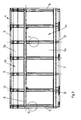
- a railway freight wagon 1 has a lower frame 2, fixed end walls 3, a narrow roof section and displaceable side walls 4 with lower side wall part 4a (vertical area) and upper side wall part 4b (inclined area).
- the side walls 4 are made of the material steel, in particular stainless steel, in particular ferritic stainless steel, in particular grade 1.4003, which can remain unpainted.
- the side wall part 4a has a closed steel sheet metal panel 5a and the upper side wall part 4b has a closed steel sheet metal panel 5b.
- the steel sheet metal panels 5a and 5b are at the vertical wall ends by vertical steel edge profiles 6 (detail D in FIG. 4 ).
- the lower steel plate 5a is at the lower longitudinal edge by a lower longitudinal steel profile 7 (detail C in FIG. 5 ) and at the upper longitudinal edge to the angled, upper side wall part 4b or steel sheet metal panel 5b by a steel Eckholmprofil 8 (detail B in FIG. 5 ).
- the upper side wall part 4b or the upper steel sheet metal panel 5b is at the top by a steel end profile 9 (detail A in FIG. 5 ) and bordered below by the aforementioned steel Eckholmprofil 8 or limited.
- the steel cross-sections 10 are mounted on the lower steel panel 5a and the steel cross-sections 11 are mounted on the upper steel panel.
- the steel cross-sections 10, 11 are preferably connected by laser or spot welding to the steel sheet panels 5a and 5b.
- the steel cross-sections 10, 11 are integrally formed as so-called hat profiles, with a belt, two lateral webs and each right and left on the webs a molded flange.
- the webs can be vertical or inclined.
- the flanges can be horizontal or angled.
- the steel Eckholm profile 8 the steel edge profiles 6 and the lower longitudinal steel profile 7 are also formed as hat profiles or modified hat profiles with one-sided lugs 6a, 7a on a belt.
- the end profile 9 is formed as a Z-profile. Overall, it should be noted that it is all in the shape of the profiles 6, 7, 8, 9, 10, 11 are inexpensive to produce, open profiles. These can be produced and designed as bending profiles (bending bench) or as hot or cold-profiled profiles (rolling or profile line).
- the steel sheet metal panels 5a and 5b are formed as a full-surface board on which the profiles 6, 7, 8, 9, 10, 11 mounted and fixedly connected to these, in particular welded, whereby a stable supporting structure is formed.
- the steel edge profiles 6 are formed as Hutprofile with one-sided, the steel sheet metal field 5 frontally superior, inwardly open U-shaped projection 6a.
- the lower longitudinal steel profile 7 is designed as a hat profile with at the lower flange, the car interior inclined step approach 7a.
- the lower longitudinal steel profile 7 is reinforced at the force application points to the steel cross sections 10 by tethered caps 13.
- the steel Eckholmprofil 8 between the upper and lower side wall portion 4a, 4b is formed as a hat profile with the upper side wall portion 4b angled towards first flange 8a, wherein the arrangement of the kink is merged with the transition to the angled upper steel sheet metal panel 5b and thereby this Area stiffened or strengthened.
- the second flange 8b is preferably angled inwardly at right angles to the adjacent web, which allows a more favorable connection to the steel cross-sections 10 and whereby a channel is formed.
- An arrangement with an outwardly angled flange 8b is executable.
- the steel sheet metal panel 5 is connected to the steel edge profile 6 by means of a continuous weld seam (full seam) or a discontinuous weld seam (partial seam, eg by spot or step welding).
- the lower steel sheet metal panel 5a is connected to the lower steel longitudinal profile 7 by means of a continuous weld seam (full seam) or a discontinuous weld seam (partial seam, eg by spot or step welding).
- the steel sheet metal panels 5a, 5b are connected to the steel corner spar profile 8 by means of a continuous weld seam (full seam) or a discontinuous weld seam (partial seam, eg by spot or step welding).
- the upper steel sheet metal panel 5b is with the steel end profile 9 by means of continuous weld (full seam) or discontinuous weld seam, z. B. connected by spot or step welding.
- the modern laser welding methods are also suitable for full or partial seam welding.
- steel sheet metal fields 5 is suitable steel sheet with a thickness of about 0.6 to 1.0 mm.
- sheets with a sheet thickness of 0.8 mm are used.
- the lower side wall portion 4 a (vertical area) and the upper side wall portion 4 b (oblique area) are connected by a mounting weld to the side wall / sliding wall 4.
- the upper side wall portion 4b (oblique area) has at least one, usually two longitudinal crease line (s) on which the upper cross sections 1 1 are interrupted and at which the upper side wall portion 4b is bent / folded.
- the open end faces of the upper transverse profiles 11 on the at least one bending line of the upper side wall part 4b are connected or covered by molded parts 12.
- a thin, suitably angled support plate (14) can be deposited and fastened from the inside in the region of the bend lines.
- the starting point is a flat sheet metal plate which is folded without training in the form of steel cross sections 11 on which the adapted, angled, prefabricated steel cross sections 11 are fastened. This training saves the use of moldings 12 ( Fig. 7 ).
- the inventive design of the side wall / sliding wall 4 for closed rail freight cars it is possible to create a side wall / sliding wall 4, which withstands the required loads and has no or only a small excess weight compared to a comparable aluminum side wall, but this many advantages that are there: use an economical material, even for smaller series; good weldability with many methods; Economical repair possibility, avoidance of leaks, because at risk of failure bonding and sealing - as with the aluminum side wall on the edge profiles necessary - not used or not necessary.
Landscapes
- Engineering & Computer Science (AREA)
- Mechanical Engineering (AREA)
- Life Sciences & Earth Sciences (AREA)
- Wood Science & Technology (AREA)
- Body Structure For Vehicles (AREA)
- Butt Welding And Welding Of Specific Article (AREA)
Abstract
Description
- Die Erfindung betrifft einen Eisenbahngüterwagen mit seitlichen Schiebewänden, die ein vertikales, unteres und ein nach innen abgewinkeltes, oberes Seitenwandteil aufweisen und die in Schließstellung in einer gemeinsamen Ebene liegen und durch eine Betätigungseinrichtung wahlweise in eine vor der gemeinsamen Ebene liegende, parallel zu dieser befindlichen Schiebeebene bewegbar und in Fahrzeuglängsrichtung verschiebbar sind.
- Ein derartiger Eisenbahngüterwagen ist aus der
DE 28 32 353 A1 bekannt. Die verschiebbaren Seitewandteile bestehen aus einem belastbaren Tragwerk aus Aluminiumprofilen. Die freien Felder sind mit Aluminiumblechen bedeckt, die mit den Profilen zusammen mittels diskontinuierlicher Schweißverfahren (Punkt- oder Schrittschweißverfahren und/oder Steckverfahren und dauerelastischen Dichtmitteln zur Abdichtung der Fugen zwischen Profilen und Blechen verbunden sind. Abdichtende Schweißnähte an allen Fügestellen zwischen den Randprofilen und den Blechen sind aufgrund der Materialgegebenheiten beim Werkstoff Aluminium, insbesondere bei dünnen Blechen und der Ausbildung der bisher verwendeten Profile technologisch nicht oder nicht mit wirtschaftlich vertretbarem Aufwand möglich. Die derzeit verfügbaren dauerelastischen Dichtmittel verlieren über die Jahre erfahrungsgemäß ihre dichtenden Eigenschaften, womit Feuchtigkeitsschaden am Ladegut auftreten und häufige Reparaturen an den Wagen notwendig sind. Auch Reparaturen an der Aluminium-Seitenwand sind werkstoffbedingt technisch schwierig und aufwändig. - Aus der
DE 298 13 340 U1 ist ein weiterer Eisenbahngüterwagen mit Schiebewänden bekannt, dessen Seitenwandteile ein selbstragendes Fachwerk/Tragwerk aus Stahl-Vierkantprofilen aufweisen. Die freien Flächen zwischen den Profilen sollen bevorzugt durch Planen abgedeckt werden. Weiter ist eine zweite Lösung zur Abdeckung mit dünnen Metallblechen, vorzugsweise Aluminiumblechen angegeben. Allerdings bleibt das Problem der Sicherstellung der Dichtheit der Kombination Stahlprofile plus Plane/Metallblech in den Stoß- und Anbindungsbereichen ungelöst. Auch sind Anforderungen nach einer in Querrichtung höher belastbaren Seitenwand bei dieser Bauweise schwer zu erfüllen. - Der Erfindung liegt daher die Aufgabe zugrunde, einen gattungsgemäßen Eisenbahngüterwagen derart zu verbessern, dass der Laderaum besser gegen das Eindringen von Feuchtigkeit in das Wageninnere über die Seitenwand/Schiebewand bekannter Ausbildung geschützt, die Reparaturfreundlichkeit verbessert und den hohen Beiastungsanfordungen, die Alternativen zu Abdeckplanen/Abdeckblechen erfordern, Rechnung getragen ist.
- Diese Aufgabe wird durch die im Anspruch 1 angegebenen Merkmale gelöst.
- Zweckmäßige Weiterbildungen sind in den Unteransprüchen angegeben.
- Durch die Ausbildung des Eisenbahngüterwagens gemäß den kennzeichnenden Merkmalen des Anspruchs 1 ist eine Verbesserung der Dichtigkeit bekannter Seitenwände gegen das Eindringen von Feuchtigkeit in das Wageninnere gegeben. Damit ist eine potenzielle Schädigung der Ladung vermeidbar, weil nunmehr vollflächige Platinen aus Stahlblech mit wirtschaftlich verschweißbaren offenen Stahl-Profilen auch ohne elastische Dichtmittel an den Anbindungsstellen zwischen Stahl-Profilen und Stahlblech ein praktisch feuchtigkeitsdichtes, oberes und unteres Seitenwandteil ausbilden. Die Verwendung des günstig verfügbaren und leicht bearbeitbaren Werkstoffs Stahl gegenüber Aluminium ist deutlich wirtschaftlicher und die Reparaturfreundlichkeit des Werkstoffs Stahl gegenüber Aluminium, insbesondere gegenüber den bisher verwendeten Alu-Strangpress-Profilen, macht eine wirtschaftliche Reparatur auch außerhalb von Spezialwerkstätten möglich. Durch die Ausbildung und Anordnung der Stahl-Profile und deren Verbindung mit den Stahl-Blechfeldern der oberen und unteren Seitenwandteile wird ein wirtschaftlich herzustellendes Tragwerk geschaffen, das den Gewichts- und Belastungsanforderungen voll genügt.
- Die Erfindung ist nachfolgend mit Bezug auf die Zeichnung näher beschrieben. Es zeigt:
- Fig. 1
- einen Eisenbahngüterwagen in Seitenansicht;
- Fig. 2
- eine einzelne Schiebewand des Eisenbahngüterwagens gem.
Fig. 1 in Seitenansicht; - Fig. 3
- die Schiebewand in Stirnansicht (Querschnittsansicht);
- Fig. 4
- die Einzelheiten D und E in der Darstellung gemäß
Fig. 2 im vergrößerten Maßstab; - Fig. 5
- die Einzelheiten A, B und C in der Darstellung gemäß
Fig. 3 im vergrößerten Maßstab; - Fig. 6
- das obere Seitenwandteil mit Stahl-Abschlussprofil und Knicklinien und
- Fig. 7
- ein zweites Ausführungsbeispiel des oberen Seitenwandteils mit Stahl-Abschlussprofil und Knicklinien.
- Ein erfindungsgemäßer Eisenbahngüterwagen 1 weist ein Untergestell 2, feste Stirnwände 3, einen schmalen Dachabschnitt sowie verschiebbare Seitenwände 4 mit unterem Seitenwandteil 4a (Vertikalbereich) und oberem Seitenwandteil 4b (Schrägbereich) auf. Die Seitenwände 4 bestehen aus dem Werkstoff Stahl, insbesondere Edelstahl, insbesondere ferritischem Edelstahl, insbesondere der Güte 1.4003, der unlackiert bleiben kann. Das Seitenwandteil 4 a weist ein geschlossenes Stahl-Blechfeld 5a und das obere Seitenwandteil 4b ein geschlossenes Stahl-Blechfeld 5b auf.
- Die Stahl-Blechfelder 5a und 5b sind an den vertikalen Wandenden durch vertikale Stahl-Randprofile 6 (Einzelheit D in
Figur 4 ) eingefasst. Das untere Stahl-Blechfeld 5a ist am unteren Längsrand durch ein unteres Stahl-Längsprofil 7 (Einzelheit C inFigur 5 ) und am oberen Längsrand zum abgewinkelten, oberen Seitenwandteil 4b bzw. Stahl-Blechfeld 5b durch ein Stahl-Eckholmprofil 8 (Einzelheit B inFigur 5 ) eingefasst. - Das obere Seitenwandteil 4b bzw. das obere Stahl-Blechfeld 5b ist oben durch ein Stahl-Abschlussprofil 9 (Einzelheit A in
Figur 5 ) und unten durch das vorgenannte Stahl-Eckholmprofil 8 eingefasst bzw. begrenzt. - Innerhalb der Blechfelder sind vertikal zu den Längsprofilen angeordnete Stahl-Querprofile 10, 11 auf den Stahl-Blechfeldern 5a und 5b angeordnet (Einzelheit E in
Figur 4 ) und dort befestigt. Im einzelnen sind die Stahl-Querprofile 10 auf dem unteren Stahl-Blechfeld 5a und die Stahl-Querprofile 11 auf dem oberen Stahl-Blechfeld befestigt. Die Stahl-Querprofile 10, 11 sind vorzugsweise mittels Laser-oder Punktschweißung mit dem Stahl-Blechfeldern 5a und 5b verbunden. - Die Stahl-Querprofile 10, 11 sind als sogenannte Hutprofile einstückig ausgebildet, mit einem Gurt, zwei seitlichen Stegen und jeweils rechts und links an den Stegen einem angeformten Flansch. Die Stege können senkrecht oder geneigt verlaufen. Die Flansche können horizontal oder abgewinkelt verlaufen.
- Das Stahl-Eckholm-Profil 8, die Stahl-Randprofile 6 und das untere Stahl-Längsprofil 7 sind gleichfalls als Hutprofile oder modifizierte Hutprofile mit einseitigen Ansätzen 6a, 7a an einem Gurt ausgebildet.
- Das Abschlussprofil 9 ist als Z-Profil ausgebildet. Übergreifend ist festzuhalten, dass es sich bei der Gestalt der Profile 6, 7, 8, 9, 10, 11 sämtlich um preiswert herzustellende, offene Profile handelt. Diese können als Abkantprofile (Abkantbank) oder als warm- oder kaltprofilierte Profile (Walz- oder Profilstraße) erzeugt und ausgebildet sein.
- Die Stahl-Blechfelder 5a und 5b sind als vollflächige Platine ausgebildet, auf die die Profile 6, 7, 8, 9, 10, 11 aufgesetzt und mit diesen fest verbunden, insbesondere verschweißt sind, womit ein stabiles Tragwerk gebildet ist.
- Die Stahl-Randprofile 6 sind als Hutprofile mit einseitigem, das Stahl-Blechfeld 5 stirnseitig überragenden, nach innen geöffnetem U-förmigem Ansatz 6a ausgebildet sind.
- Das untere Stahl-Längsprofil 7 ist als Hutprofil mit am unteren Flansch, zum Wageninneren geneigtem Stufenansatz 7a ausgebildet ist. Das untere Stahl-Längsprofil 7 ist an den Kraftansatzpunkten zu den Stahl-Querprofilen 10 durch angebundene Kappen 13 verstärkt.
- Das Stahl-Eckholmprofil 8 zwischen oberen und unterem Seitenwandteil 4a, 4b als Hutprofil mit zum oberen Seitenwandteil 4b hin abgewinkeltem, erstem Flansch 8a ausgebildet ist, wobei die Anordnung der Knickstelle mit dem Übergang zum abgewinkeltem, oberen Stahl-Blechfeld 5b zusammengelegt ist und dadurch diesen Bereich versteift bzw. verstärkt. Der zweite Flansch 8b ist vorzugsweise im rechten Winkel zum benachbarten Steg nach innen abgewinkelt, was eine günstigere Anbindung an die Stahl-Querprofile 10 ermöglicht und wodurch eine Rinne gebildet ist. Auch eine Anordnung mit nach aussen abgewinkeltem Flansch 8b ist ausführbar.
- Das Stahl-Blechfeld 5 ist mit dem Stahl- Randprofil 6 mittels kontinuierlicher Schweißnaht (Vollnaht) oder diskontinuierlicher Schweißnaht (Teilnaht, z. B. durch Punkt- oder Schrittschweißung) verbunden.
- Das untere Stahl-Blechfeld 5a ist mit dem unteren Stahl-Längsprofil 7 mittels kontinuierlicher Schweißnaht (Vollnaht) oder diskontinuierlicher Schweißnaht (Teilnaht, z. B. durch Punkt- oder Schrittschweißung) verbunden.
- Die Stahl-Blechfelder 5a, 5b sind mit dem Stahl-Eckholmprofil 8 mittels kontinuierlicher Schweißnaht (Vollnaht) oder diskontinuierlicher Schweißnaht (Teilnaht, z. B. durch Punkt- oder Schrittschweißung) verbunden.
- Das obere Stahl-Blechfeld 5b ist mit dem Stahl-Abschlussprofil 9 mittels kontinuierlicher Schweißnaht (Vollnaht) oder diskontinuierlicher Schweißnaht Teilnaht, z. B. durch Punkt- oder Schrittschweißung verbunden.
- Grundsätzlich eignen sich zur Voll- oder Teilnahtschweißung auch die neuzeitlichen Laserschweißverfahren.
- Für die Stahl-Blechfelder 5 eignet sich Stahlblech mit einer Blechdicken von etwa 0,6 bis 1,0 mm. Vorzugsweise werden Bleche mit der Blechdicke 0,8 mm verwendet.
- Für die Stahl-Profile 6, 7, 8 ,9, 10, 11 sind Materialstärken im Bereich von etwa 1,0 bis 2,0 mm vorgesehen, wobei die vorgenannten Stahlprofile in diesem Bereich mit unterschiedlicher Materialstärke ausgebildet sein können. D.h. zur belastungsangepassten, optimierten Auslegung der Seitenwand/Schiebewand 4 können Stahlprofile unterschiedlicher Materialstärke kombiniert eingesetzt sein.
- Das untere Seitenwandteil 4 a (Vertikalbereich) und das obere Seitenwandteil 4b (Schrägbereich) sind durch eine Montageschweißung zur Seitenwand/Schiebewand 4 verbunden sind.
- Das obere Seitenwandteil 4b (Schrägbereich) weist mindestens eine, im Regelfall zwei längslaufende Knicklinie(n) auf, an der die oberen Querprofile 1 1 unterbrochen sind und an der das obere Seitenwandteil 4b abgeknickt/abgekantet ist.
- Die offenen Stirnseiten der oberen Querprofile 11 an der mindestens einen Knicklinie des oberes Seitenwandteils 4b sind durch Formteile 12 verbunden bzw. abgedeckt sind.
- Bei dieser Lösung zur Herstellung des oberen Seitenwandteils 4b wird von einem eben Blechfeld 5b ausgegangen, das nach dem Aufsetzen und Befestigen der an den vorgesehen Knicklinien unterbrochenen Blech-Querprofile 11 das obere Seitenwandteil 4b in die benötigte, abgewinkelte Form gekantet wird (
Fig. 6 ). - Nach der Kantung werden in die entstandenen Zwischenräume zwischen benachbarten Stahl-Querprofilen 11 an deren Stirnseiten im Bereich der Knicklinien Formteile 12 eingefügt, die die Form des oberen Seitenwandteils 4b stabilisieren und die Stirnseiten der Stahl-Querprofile 11 abdecken.
- Zur Stabilisierung des oberen Seitenwandteils 4b kann im Bereich der Knicklinien ein dünnes, angepasst abgewinkeltes Stützblech (14) von innen hinterlegt und befestigt sein.
- In einem zweiten Ausführungsbeispiel zur Erzeugung des oberen Seitenwandteils 4b wird von einer ebenen Blechplatine ausgegangen, die ohne Stahl-Querprofile 11 ausbildungsgemäß abgekantet wird/ist, auf die die angepassten, abgewinkelten, vorgefertigte Stahl-Querprofile 11 befestigt werden/sind. Diese Ausbildung erspart die Verwendung von Formteilen 12 (
Fig. 7 ). - Durch die erfindungsgemäße Ausbildung der Seitenwand/Schiebewand 4 für geschlossene Eisenbahngüterwagen ist es möglich eine Seitenwand/Schiebewand 4 zu schaffen, die den geforderten Belastungen Stand hält und die kein oder nur ein geringes Mehrgewicht gegenüber einer vergleichbaren Aluminium-Seitenwand aufweist, aber dieser gegenüber viele Vorteile aufweist, die da sind: Verwendung eines wirtschaftlichen Werkstoffes, auch für kleinere Serien; gute Schweißbarkeit mit vielen Verfahren; wirtschaftliche Reparaturmöglichkeit, Vermeidung von Undichtigkeiten, weil versagensgefährdete Klebungen und Abdichtungen - wie bei der Aluminium-Seitenwand an den Randprofilen notwendig- nicht verwendet bzw. nicht nötig sind.
-
- 1
- Eisenbahngüterwagen/Wagen
- 2
- Untergestell
- 3
- Stirnwand
- 4
- Seitenwand/Schiebewand
- 4a
- unteres Seitenwandteil (Vertikalbereich)
- 4b
- oberes Seitenwandteil (Schrägbereich)
- 5
- Stahl-Blechfeld
- 5a
- unteres Stahl-Blechfeld (Vertikalbereich)
- 5b
- oberes Stahl-Blechfeld (Schrägbereich)
- 6
- Stahl-Randprofil
- 6a
- u-förmiger Ansatz
- 7
- Stahl-Längsprofil
- 7a
- Stufen-Ansatz
- 8
- Stahl-Eckholmprofil
- 8a
- abgewinkelter, erster Flansch
- 8b
- abgewinkelter, zweiter Flansch
- 9
- Stahl-Abschlussprofil
- 10
- Stahl-Querprofil
- 1 1
- oberes Stahl-Querprofil
- 12
- Formteil
- 13
- Kappe
- 14
- Stützblech
Claims (22)
- Eisenbahngüterwagen (1) mit seitlichen Schiebewänden (4), die ein vertikales, unteres Seitenwandteil (4a) und ein nach innen abgewinkeltes, oberes Seitenwandteil (4b) aufweisen und die in Schließstellung in einer gemeinsamen Ebene liegen und durch eine Betätigungseinrichtung wahlweise in eine vor der gemeinsamen Ebene liegende, parallel zu dieser befindlichen Schiebeebene bewegbar und in Fahrzeuglängsrichtung verschiebbar sind, dadurch gekennzeichnet, dass die Schiebewände (4) aus dem Werkstoff Stahl sind, dass das untere Seitenwandteil (4a) ein unteres, geschlossenes Stahl-Blechfeld (5a) und das obere Seitenwandteil (4b) ein oberes, geschlossenes Stahl-Blechfeld (5b) aufweist, die an den vertikalen Wandenden durch vertikale Stahl-Randprofile (6) eingefasst sind, dass das untere Stahlblechfeld (5a) am unteren Längsrand durch ein unteres Stahl-Längsprofil (7) und am oberen Längsrand zum abgewinkelten, oberen Seitenwandteil (4b) durch ein oberes Stahl-Eckholmprofil (8) und das obere Stahl-Blechfeld (5b) durch ein Stahl-Abschlussprofil (9) eingefasst sind, wobei die vorgenannten Stahl-Profile (6, 7, 8, 9) als offene Profile ausgebildet sind, dass innerhalb der Blechfelder vertikal zu den Längsprofilen angeordnete Stahl-Querprofile (10, 11) auf den Stahl-Blechfeldern (5a und 5b) befestigt sind und dass die Stahl-Querprofile (10, 11) als Hutprofile ausgebildet sind, die zusammen mit den, die offene Seite der Hutprofile abdeckenden Stahl-Blechfeldern (5a, 5b) ein geschlossenes Profil ausbilden.
- Eisenbahngüterwagen nach Anspruch 1, dadurch gekennzeichnet, dass das Stahl-Eckholmprofil (8), die Stahl-Randprofile (6) und das untere Stahl-Längsprofil (7) als Hutprofile oder modifizierte Hutprofile mit einseitigen Ansätzen (6a, 7a) ausgebildet sind.
- Eisenbahngüterwagen nach Anspruch 1 oder 2, dadurch gekennzeichnet, dass die Stahl-Randprofile (6) als Hutprofile mit einseitigem, das Stahl-Blechfeld (5) stirnseitig überragenden, nach innen geöffnetem U-förmigem Ansatz (6a) ausgebildet sind.
- Eisenbahngüterwagen nach Anspruch 1 oder 2, dadurch gekennzeichnet, dass das untere Stahl-Längsprofil (7) als Hutprofil mit am unteren Steg, zum Wageninneren geneigtem Stufenansatz (7a) ausgebildet ist.
- Eisenbahngüterwagen nach Anspruch 4, dadurch gekennzeichnet, dass das untere Stahl-Längsprofil (7) an den Kraftansatzpunkten zu den Stahl-Querprofilen (10) durch angebundene Kappen (13) verstärkt ist .
- Eisenbahngüterwagen nach Anspruch 1 oder 2, dadurch gekennzeichnet, dass das Stahl-Eckholmprofil (8) zwischen oberen und unterem Seitenwandteil (4a, 4b) als Hutprofil mit einem zum oberen Seitenwandteil (4b) hin abgewinkelten, ersten Flansch (8a) und einem im rechten Winkel zum benachbarten Steg nach innen abgewinkelten, zweiten Flansch (8b) ausgebildet ist.
- Eisenbahngüterwagen nach einem oder mehreren der Ansprüche 1 bis 6, dadurch gekennzeichnet, dass die Stahlprofile (6, 7, 8, 9, 10, 11) als Abkontprofile ausgebildet sind.
- Eisenbahngüterwagen nach einem oder mehreren der Ansprüche 1 bis 6, dadurch gekennzeichnet, dass die Stahlprofile (6, 7, 8, 9, 10, 11) kaltprofilierte Profile sind.
- Eisenbahngüterwagen nach einem oder mehreren der Ansprüche 1 bis 8, dadurch gekennzeichnet, dass die Stahlprofile (6, 7, 8 , 9, 10, 11) und die Stahl-Blechfelder (5) aus Edelstahl, insbesondere ferritischem Edelstahl bestehen.
- Eisenbahngüterwagen nach einem oder mehreren der Ansprüche 1 bis 9, dadurch gekennzeichnet, dass das Stahl-Blechfeld (5) mit dem Stahl-Randprofil (6) mittels kontinuierlicher Schweißnaht (Vollnaht) oder diskontinuierlicher Schweißnaht (Teilnaht, z. B. durch Punkt- oder Schrittschweißung) verbunden ist.
- Eisenbahngüterwagen nach einem oder mehreren der Ansprüche 1 bis 9, dadurch gekennzeichnet, dass das untere Stahl-Blechfeld (4a) mit dem unteren Stahl-Längsprofil (7) mittels kontinuierlicher Schweißnaht (Vollnaht) oder diskontinuierlicher Schweißnaht (Teilnaht, z. B. durch Punkt- oder Schrittschweißung) verbunden ist.
- Eisenbahngüterwagen nach einem oder mehreren der Ansprüche 1 bis 9, dadurch gekennzeichnet, dass die Stahl-Blechfelder (5a, 5b) mit dem Stahl-Eckholmprofil (8) mittels kontinuierlicher Schweißnaht (Vollnaht) oder diskontinuierlicher Schweißnaht (Teilnaht, z. B. durch Punkt- oder Schrittschweißung) verbunden ist.
- Eisenbahngüterwagen nach einem oder mehreren der Ansprüche 1 bis 9, dadurch gekennzeichnet, dass das obere Stahl-Blechfeld (5b) mit dem Stahl-Abschlussprofil (9) mittels kontinuierlicher Schweißnaht (Vollnaht) oder diskontinuierlicher Schweißnaht (Teilnaht, z. B. durch Punkt- oder Schrittschweißung) verbunden ist.
- Eisenbahngüterwagen nach einem oder mehreren der Ansprüche 1 bis 13, dadurch gekennzeichnet, dass das/die Stahl-Blechfeld/er (5) eine Blechdicke von etwa 0,6 bis 1,0 mm, vorzugsweise 0,8 mm aufweist/aufweisen.
- Eisenbahngüterwagen nach einem oder mehreren der Ansprüche 1 bis 14, dadurch gekennzeichnet, dass die Stahl-Profile (6, 7, 8 ,9, 10, 11) eine Materialstärke von etwa 1,0 bis 2,0 mm aufweisen.
- Eisenbahngüterwagen nach einem oder mehreren der Ansprüche 1 bis 15, dadurch gekennzeichnet, dass das untere Seitenwandteil (4 a) (Vertikalbereich) und das obere Seitenwandteil (4b) (Schrägbereich) durch eine Montageschweißung zur Seitenwand/Schiebewand (4) verbunden sind.
- Eisenbahngüterwagen nach einem oder mehreren der Ansprüche 1 bis 16, dadurch gekennzeichnet, dass das oberes Seitenwandteil (4b) (Schrägbereich) mindestens eine längslaufende Knicklinie aufweist, an der die oberen Querprofile (11) unterbrochen sind und an der das obere Seitenwandteil (4b) abgeknickt/abgekantet ist.
- Eisenbahngüterwagen nach Anspruche 17, dadurch gekennzeichnet, dass die offenen Stirnseiten der oberen Querprofile (11) an der mindestens einen Knicklinie des oberes Seitenwandteils (4b) durch Formteile (12) verbunden bzw. abgedeckt sind.
- Eisenbahngüterwagen nach einem oder mehreren der Ansprüche 1 bis 18, dadurch gekennzeichnet, dass das oberes Seitenwandteil (4b) (Schrägbereich) mindestens eine längslaufende Knicklinie aufweist, an der die einstückig ausgebildeten, oberen Querprofile (11) entsprechend den Winkelvorgaben angepasst abgewinkelt sind und mit dem entsprechend gekanteten, oberen Stahl-Blechfeld (5b) verbunden sind.
- Eisenbahngüterwagen nach Anspruch 17, 18 oder 19, dadurch gekennzeichnet, dass das obere Seitenwandteil (4b) im Bereich der mindestens einen Knicklinie durch ein dünnes, angepasst abgewinkeltes Stützblech (14) von innen hinterlegt und befestigt ist.
- Eisenbahngüterwagen nach einem oder mehreren der Ansprüche 1 bis 20, dadurch gekennzeichnet, dass die Stahl-Blechfelder (5a, 5b) als vollflächige Platinen ausgebildet sind, auf die die Profile (6, 7, 8, 9, 10, 11) aufgesetzt und mit diesen verbunden, insbesondere verschweißt sind.
- Eisenbahngüterwagen nach einem oder mehreren der Ansprüche 1 bis 21, dadurch gekennzeichnet, dass die Stahl-Querprofile (10, 11) mittels Laser- oder Punktschweißung mit dem Stahl-Blechfeld (5) verbunden sind.
Priority Applications (1)
| Application Number | Priority Date | Filing Date | Title |
|---|---|---|---|
| PL07024091T PL1935743T3 (pl) | 2006-12-21 | 2007-12-12 | Kolejowy wagon towarowy z bocznymi ścianami przesuwnymi |
Applications Claiming Priority (1)
| Application Number | Priority Date | Filing Date | Title |
|---|---|---|---|
| DE102006060545A DE102006060545A1 (de) | 2006-12-21 | 2006-12-21 | Eisenbahngüterwagen mit seitlichen Schiebewänden, die ein vertikales, unteres und ein nach innen abgewinkeltes, oberes Seitenwandteil aufweisen und die in Schließstellung in einer gemeinsamen Ebene liegen und durch eine Betätigungseinrichtung wahlweise in eine vor der gemeinsamen Ebene liegende, parallel zu dieser befindlichen Schiebeebene bewegbar und in Fahrzeuglängsrichtung verschiebbar sind |
Publications (2)
| Publication Number | Publication Date |
|---|---|
| EP1935743A1 true EP1935743A1 (de) | 2008-06-25 |
| EP1935743B1 EP1935743B1 (de) | 2012-06-13 |
Family
ID=39307917
Family Applications (1)
| Application Number | Title | Priority Date | Filing Date |
|---|---|---|---|
| EP07024091A Active EP1935743B1 (de) | 2006-12-21 | 2007-12-12 | Eisenbahngüterwagen mit seitlichen Schiebewänden |
Country Status (4)
| Country | Link |
|---|---|
| EP (1) | EP1935743B1 (de) |
| DE (1) | DE102006060545A1 (de) |
| ES (1) | ES2387541T3 (de) |
| PL (1) | PL1935743T3 (de) |
Cited By (2)
| Publication number | Priority date | Publication date | Assignee | Title |
|---|---|---|---|---|
| EP2431247A3 (de) * | 2010-09-15 | 2013-01-23 | Bombardier Transportation GmbH | Fahrzeugkastenstruktur und Fahrzeug |
| CN110001786A (zh) * | 2019-03-04 | 2019-07-12 | 威海顺丰专用车制造股份有限公司 | 一种全承载轻量一体化半挂车车体 |
Families Citing this family (1)
| Publication number | Priority date | Publication date | Assignee | Title |
|---|---|---|---|---|
| PL2246234T3 (pl) | 2009-04-02 | 2017-07-31 | Wbn Waggonbau Niesky Gmbh | Boczny przesuwny element ścienny dla wagonu towarowego |
Citations (4)
| Publication number | Priority date | Publication date | Assignee | Title |
|---|---|---|---|---|
| DE2832353A1 (de) * | 1978-07-22 | 1980-02-07 | Waggon Union Gmbh | Gedeckter eisenbahngueterwagen |
| EP0412794A2 (de) * | 1989-08-09 | 1991-02-13 | Hitachi, Ltd. | Wagenkasten für Schienenfahrzeug |
| EP0573351A1 (de) | 1992-06-03 | 1993-12-08 | Gec Alsthom Transport Sa | Wagenkasten aus rostfreiem Stahl für Schienenfahrzeug |
| DE202004015077U1 (de) | 2004-09-28 | 2004-11-25 | Greenbrier Germany Gmbh | Schiebewand für Eisenbahngüterwagen |
Family Cites Families (1)
| Publication number | Priority date | Publication date | Assignee | Title |
|---|---|---|---|---|
| CA2316148A1 (en) * | 2000-08-16 | 2002-02-16 | Glenn Macdonald | Horizontal seam boxcar side wall |
-
2006
- 2006-12-21 DE DE102006060545A patent/DE102006060545A1/de not_active Withdrawn
-
2007
- 2007-12-12 PL PL07024091T patent/PL1935743T3/pl unknown
- 2007-12-12 ES ES07024091T patent/ES2387541T3/es active Active
- 2007-12-12 EP EP07024091A patent/EP1935743B1/de active Active
Patent Citations (4)
| Publication number | Priority date | Publication date | Assignee | Title |
|---|---|---|---|---|
| DE2832353A1 (de) * | 1978-07-22 | 1980-02-07 | Waggon Union Gmbh | Gedeckter eisenbahngueterwagen |
| EP0412794A2 (de) * | 1989-08-09 | 1991-02-13 | Hitachi, Ltd. | Wagenkasten für Schienenfahrzeug |
| EP0573351A1 (de) | 1992-06-03 | 1993-12-08 | Gec Alsthom Transport Sa | Wagenkasten aus rostfreiem Stahl für Schienenfahrzeug |
| DE202004015077U1 (de) | 2004-09-28 | 2004-11-25 | Greenbrier Germany Gmbh | Schiebewand für Eisenbahngüterwagen |
Cited By (2)
| Publication number | Priority date | Publication date | Assignee | Title |
|---|---|---|---|---|
| EP2431247A3 (de) * | 2010-09-15 | 2013-01-23 | Bombardier Transportation GmbH | Fahrzeugkastenstruktur und Fahrzeug |
| CN110001786A (zh) * | 2019-03-04 | 2019-07-12 | 威海顺丰专用车制造股份有限公司 | 一种全承载轻量一体化半挂车车体 |
Also Published As
| Publication number | Publication date |
|---|---|
| PL1935743T3 (pl) | 2012-09-28 |
| EP1935743B1 (de) | 2012-06-13 |
| DE102006060545A1 (de) | 2008-06-26 |
| ES2387541T3 (es) | 2012-09-25 |
Similar Documents
| Publication | Publication Date | Title |
|---|---|---|
| EP0778194B1 (de) | Fahrzeug, insbesondere Strassen- oder Schienenfahrzeug, mit einem Skelett | |
| EP3849924A1 (de) | Schüttgutcontainer | |
| EP0964807B1 (de) | Rahmen zum befestigen von flächenelementen | |
| EP1935743B1 (de) | Eisenbahngüterwagen mit seitlichen Schiebewänden | |
| DE102010011568A1 (de) | Wagenkasten eines Schienenfahrzeugs und Verfahren zu seiner Herstellung | |
| EP2483123B1 (de) | Grosskomponente für schienenfahrzeuge | |
| EP1621675A1 (de) | Element für Lärmschutzwände | |
| DE19807747B4 (de) | Karosserieabschnitt eines Kraftfahrzeuges | |
| EP1640236B1 (de) | Schiebewand für Eisenbahngüterwagen | |
| EP2246234B1 (de) | Seitliches Schiebewandelement für Eisenbahngüterwagen | |
| DE202006019248U1 (de) | Eisenbahngüterwagen mit seitlichen Schiebewänden | |
| EP3016829B1 (de) | Fahrzeug, insbesondere schienenfahrzeug, mit einem hochflur- und einem niederflurbereich | |
| DE102013216821B4 (de) | Karosseriestruktur für ein Fahrzeug | |
| DE19607755A1 (de) | Bordwandeinrichtung für Lastfahrzeuge | |
| EP2431247B1 (de) | Fahrzeugkastenstruktur und Fahrzeug | |
| EP1686033B1 (de) | Untergestell eines Fahrwerkmoduls für Niederflur-Schienenfahrzeuge | |
| DE4447399C2 (de) | Firstträger für Eisenbahngüterwagen | |
| DE754836C (de) | Selbsttragender Wagenkasten aus Metall fuer Fahrzeuge, insbesondere Schienenfahrzeuge | |
| EP1806259B1 (de) | Plattform für eine Hubladebühne für Lastkraftfahrzeuge | |
| DE19537770A1 (de) | Wagenkastenaufbau für Fahrzeuge, insbesondere Schienenfahrzeuge | |
| DE4102476A1 (de) | Selbsttragende haube fuer fahrzeuge | |
| EP4341146A1 (de) | Seitenwand für ein schienenfahrzeug | |
| AT293470B (de) | Türblatt für Güterwagenschiebetüren | |
| DE19903722A1 (de) | Wagenkastenseitenwand für Großraumfahrzeuge, insbesondere Omnibusse | |
| EP3590795A1 (de) | Paneelstrukturelement eines aufbaus eines nutzfahrzeugs sowie kofferaufbau und nutzfahrzeug |
Legal Events
| Date | Code | Title | Description |
|---|---|---|---|
| PUAI | Public reference made under article 153(3) epc to a published international application that has entered the european phase |
Free format text: ORIGINAL CODE: 0009012 |
|
| AK | Designated contracting states |
Kind code of ref document: A1 Designated state(s): AT BE BG CH CY CZ DE DK EE ES FI FR GB GR HU IE IS IT LI LT LU LV MC MT NL PL PT RO SE SI SK TR |
|
| AX | Request for extension of the european patent |
Extension state: AL BA HR MK RS |
|
| 17P | Request for examination filed |
Effective date: 20081209 |
|
| 17Q | First examination report despatched |
Effective date: 20090113 |
|
| AKX | Designation fees paid |
Designated state(s): AT BE BG CH CY CZ DE DK EE ES FI FR GB GR HU IE IS IT LI LT LU LV MC MT NL PL PT RO SE SI SK TR |
|
| RAP1 | Party data changed (applicant data changed or rights of an application transferred) |
Owner name: ALSTOM TRANSPORT DEUTSCHLAND GMBH |
|
| GRAP | Despatch of communication of intention to grant a patent |
Free format text: ORIGINAL CODE: EPIDOSNIGR1 |
|
| RIN1 | Information on inventor provided before grant (corrected) |
Inventor name: BOEHM, WOLFGANG Inventor name: BEIER, GUENTER |
|
| GRAS | Grant fee paid |
Free format text: ORIGINAL CODE: EPIDOSNIGR3 |
|
| GRAA | (expected) grant |
Free format text: ORIGINAL CODE: 0009210 |
|
| AK | Designated contracting states |
Kind code of ref document: B1 Designated state(s): AT BE BG CH CY CZ DE DK EE ES FI FR GB GR HU IE IS IT LI LT LU LV MC MT NL PL PT RO SE SI SK TR |
|
| REG | Reference to a national code |
Ref country code: GB Ref legal event code: FG4D Free format text: NOT ENGLISH |
|
| REG | Reference to a national code |
Ref country code: AT Ref legal event code: REF Ref document number: 561849 Country of ref document: AT Kind code of ref document: T Effective date: 20120615 Ref country code: CH Ref legal event code: EP |
|
| REG | Reference to a national code |
Ref country code: IE Ref legal event code: FG4D Free format text: LANGUAGE OF EP DOCUMENT: GERMAN |
|
| REG | Reference to a national code |
Ref country code: DE Ref legal event code: R096 Ref document number: 502007010030 Country of ref document: DE Effective date: 20120816 |
|
| REG | Reference to a national code |
Ref country code: NL Ref legal event code: T3 |
|
| REG | Reference to a national code |
Ref country code: ES Ref legal event code: FG2A Ref document number: 2387541 Country of ref document: ES Kind code of ref document: T3 Effective date: 20120925 |
|
| REG | Reference to a national code |
Ref country code: PL Ref legal event code: T3 |
|
| PG25 | Lapsed in a contracting state [announced via postgrant information from national office to epo] |
Ref country code: LT Free format text: LAPSE BECAUSE OF FAILURE TO SUBMIT A TRANSLATION OF THE DESCRIPTION OR TO PAY THE FEE WITHIN THE PRESCRIBED TIME-LIMIT Effective date: 20120613 Ref country code: FI Free format text: LAPSE BECAUSE OF FAILURE TO SUBMIT A TRANSLATION OF THE DESCRIPTION OR TO PAY THE FEE WITHIN THE PRESCRIBED TIME-LIMIT Effective date: 20120613 Ref country code: SE Free format text: LAPSE BECAUSE OF FAILURE TO SUBMIT A TRANSLATION OF THE DESCRIPTION OR TO PAY THE FEE WITHIN THE PRESCRIBED TIME-LIMIT Effective date: 20120613 Ref country code: CY Free format text: LAPSE BECAUSE OF FAILURE TO SUBMIT A TRANSLATION OF THE DESCRIPTION OR TO PAY THE FEE WITHIN THE PRESCRIBED TIME-LIMIT Effective date: 20120613 |
|
| REG | Reference to a national code |
Ref country code: LT Ref legal event code: MG4D Effective date: 20120613 |
|
| PG25 | Lapsed in a contracting state [announced via postgrant information from national office to epo] |
Ref country code: GR Free format text: LAPSE BECAUSE OF FAILURE TO SUBMIT A TRANSLATION OF THE DESCRIPTION OR TO PAY THE FEE WITHIN THE PRESCRIBED TIME-LIMIT Effective date: 20120914 Ref country code: LV Free format text: LAPSE BECAUSE OF FAILURE TO SUBMIT A TRANSLATION OF THE DESCRIPTION OR TO PAY THE FEE WITHIN THE PRESCRIBED TIME-LIMIT Effective date: 20120613 Ref country code: SI Free format text: LAPSE BECAUSE OF FAILURE TO SUBMIT A TRANSLATION OF THE DESCRIPTION OR TO PAY THE FEE WITHIN THE PRESCRIBED TIME-LIMIT Effective date: 20120613 |
|
| PG25 | Lapsed in a contracting state [announced via postgrant information from national office to epo] |
Ref country code: SK Free format text: LAPSE BECAUSE OF FAILURE TO SUBMIT A TRANSLATION OF THE DESCRIPTION OR TO PAY THE FEE WITHIN THE PRESCRIBED TIME-LIMIT Effective date: 20120613 Ref country code: IS Free format text: LAPSE BECAUSE OF FAILURE TO SUBMIT A TRANSLATION OF THE DESCRIPTION OR TO PAY THE FEE WITHIN THE PRESCRIBED TIME-LIMIT Effective date: 20121013 Ref country code: CZ Free format text: LAPSE BECAUSE OF FAILURE TO SUBMIT A TRANSLATION OF THE DESCRIPTION OR TO PAY THE FEE WITHIN THE PRESCRIBED TIME-LIMIT Effective date: 20120613 Ref country code: RO Free format text: LAPSE BECAUSE OF FAILURE TO SUBMIT A TRANSLATION OF THE DESCRIPTION OR TO PAY THE FEE WITHIN THE PRESCRIBED TIME-LIMIT Effective date: 20120613 Ref country code: EE Free format text: LAPSE BECAUSE OF FAILURE TO SUBMIT A TRANSLATION OF THE DESCRIPTION OR TO PAY THE FEE WITHIN THE PRESCRIBED TIME-LIMIT Effective date: 20120613 |
|
| PG25 | Lapsed in a contracting state [announced via postgrant information from national office to epo] |
Ref country code: PT Free format text: LAPSE BECAUSE OF FAILURE TO SUBMIT A TRANSLATION OF THE DESCRIPTION OR TO PAY THE FEE WITHIN THE PRESCRIBED TIME-LIMIT Effective date: 20121015 |
|
| PLBE | No opposition filed within time limit |
Free format text: ORIGINAL CODE: 0009261 |
|
| STAA | Information on the status of an ep patent application or granted ep patent |
Free format text: STATUS: NO OPPOSITION FILED WITHIN TIME LIMIT |
|
| PG25 | Lapsed in a contracting state [announced via postgrant information from national office to epo] |
Ref country code: DK Free format text: LAPSE BECAUSE OF FAILURE TO SUBMIT A TRANSLATION OF THE DESCRIPTION OR TO PAY THE FEE WITHIN THE PRESCRIBED TIME-LIMIT Effective date: 20120613 |
|
| 26N | No opposition filed |
Effective date: 20130314 |
|
| BERE | Be: lapsed |
Owner name: ALSTOM TRANSPORT DEUTSCHLAND G.M.B.H. Effective date: 20121231 |
|
| REG | Reference to a national code |
Ref country code: DE Ref legal event code: R097 Ref document number: 502007010030 Country of ref document: DE Effective date: 20130314 |
|
| PG25 | Lapsed in a contracting state [announced via postgrant information from national office to epo] |
Ref country code: BG Free format text: LAPSE BECAUSE OF FAILURE TO SUBMIT A TRANSLATION OF THE DESCRIPTION OR TO PAY THE FEE WITHIN THE PRESCRIBED TIME-LIMIT Effective date: 20120913 Ref country code: MC Free format text: LAPSE BECAUSE OF NON-PAYMENT OF DUE FEES Effective date: 20121231 |
|
| REG | Reference to a national code |
Ref country code: IE Ref legal event code: MM4A |
|
| PG25 | Lapsed in a contracting state [announced via postgrant information from national office to epo] |
Ref country code: BE Free format text: LAPSE BECAUSE OF NON-PAYMENT OF DUE FEES Effective date: 20121231 |
|
| PG25 | Lapsed in a contracting state [announced via postgrant information from national office to epo] |
Ref country code: IE Free format text: LAPSE BECAUSE OF NON-PAYMENT OF DUE FEES Effective date: 20121212 |
|
| PG25 | Lapsed in a contracting state [announced via postgrant information from national office to epo] |
Ref country code: MT Free format text: LAPSE BECAUSE OF FAILURE TO SUBMIT A TRANSLATION OF THE DESCRIPTION OR TO PAY THE FEE WITHIN THE PRESCRIBED TIME-LIMIT Effective date: 20120613 |
|
| PG25 | Lapsed in a contracting state [announced via postgrant information from national office to epo] |
Ref country code: TR Free format text: LAPSE BECAUSE OF FAILURE TO SUBMIT A TRANSLATION OF THE DESCRIPTION OR TO PAY THE FEE WITHIN THE PRESCRIBED TIME-LIMIT Effective date: 20120613 |
|
| PG25 | Lapsed in a contracting state [announced via postgrant information from national office to epo] |
Ref country code: LU Free format text: LAPSE BECAUSE OF NON-PAYMENT OF DUE FEES Effective date: 20121212 |
|
| PG25 | Lapsed in a contracting state [announced via postgrant information from national office to epo] |
Ref country code: HU Free format text: LAPSE BECAUSE OF FAILURE TO SUBMIT A TRANSLATION OF THE DESCRIPTION OR TO PAY THE FEE WITHIN THE PRESCRIBED TIME-LIMIT Effective date: 20071212 |
|
| REG | Reference to a national code |
Ref country code: FR Ref legal event code: PLFP Year of fee payment: 9 |
|
| REG | Reference to a national code |
Ref country code: FR Ref legal event code: PLFP Year of fee payment: 10 |
|
| REG | Reference to a national code |
Ref country code: FR Ref legal event code: PLFP Year of fee payment: 11 |
|
| PGFP | Annual fee paid to national office [announced via postgrant information from national office to epo] |
Ref country code: FR Payment date: 20201223 Year of fee payment: 14 Ref country code: GB Payment date: 20201223 Year of fee payment: 14 Ref country code: AT Payment date: 20201222 Year of fee payment: 14 Ref country code: CH Payment date: 20201221 Year of fee payment: 14 Ref country code: DE Payment date: 20201211 Year of fee payment: 14 |
|
| PGFP | Annual fee paid to national office [announced via postgrant information from national office to epo] |
Ref country code: PL Payment date: 20201204 Year of fee payment: 14 |
|
| PGFP | Annual fee paid to national office [announced via postgrant information from national office to epo] |
Ref country code: NL Payment date: 20201221 Year of fee payment: 14 |
|
| PGFP | Annual fee paid to national office [announced via postgrant information from national office to epo] |
Ref country code: IT Payment date: 20201224 Year of fee payment: 14 |
|
| PGFP | Annual fee paid to national office [announced via postgrant information from national office to epo] |
Ref country code: ES Payment date: 20210222 Year of fee payment: 14 |
|
| REG | Reference to a national code |
Ref country code: DE Ref legal event code: R119 Ref document number: 502007010030 Country of ref document: DE |
|
| REG | Reference to a national code |
Ref country code: CH Ref legal event code: PL |
|
| REG | Reference to a national code |
Ref country code: NL Ref legal event code: MM Effective date: 20220101 |
|
| REG | Reference to a national code |
Ref country code: AT Ref legal event code: MM01 Ref document number: 561849 Country of ref document: AT Kind code of ref document: T Effective date: 20211212 |
|
| GBPC | Gb: european patent ceased through non-payment of renewal fee |
Effective date: 20211212 |
|
| PG25 | Lapsed in a contracting state [announced via postgrant information from national office to epo] |
Ref country code: NL Free format text: LAPSE BECAUSE OF NON-PAYMENT OF DUE FEES Effective date: 20220101 |
|
| PG25 | Lapsed in a contracting state [announced via postgrant information from national office to epo] |
Ref country code: GB Free format text: LAPSE BECAUSE OF NON-PAYMENT OF DUE FEES Effective date: 20211212 Ref country code: DE Free format text: LAPSE BECAUSE OF NON-PAYMENT OF DUE FEES Effective date: 20220701 Ref country code: AT Free format text: LAPSE BECAUSE OF NON-PAYMENT OF DUE FEES Effective date: 20211212 |
|
| PG25 | Lapsed in a contracting state [announced via postgrant information from national office to epo] |
Ref country code: FR Free format text: LAPSE BECAUSE OF NON-PAYMENT OF DUE FEES Effective date: 20211231 |
|
| PG25 | Lapsed in a contracting state [announced via postgrant information from national office to epo] |
Ref country code: LI Free format text: LAPSE BECAUSE OF NON-PAYMENT OF DUE FEES Effective date: 20211231 Ref country code: CH Free format text: LAPSE BECAUSE OF NON-PAYMENT OF DUE FEES Effective date: 20211231 |
|
| PG25 | Lapsed in a contracting state [announced via postgrant information from national office to epo] |
Ref country code: IT Free format text: LAPSE BECAUSE OF NON-PAYMENT OF DUE FEES Effective date: 20211212 |
|
| REG | Reference to a national code |
Ref country code: ES Ref legal event code: FD2A Effective date: 20230222 |
|
| PG25 | Lapsed in a contracting state [announced via postgrant information from national office to epo] |
Ref country code: ES Free format text: LAPSE BECAUSE OF NON-PAYMENT OF DUE FEES Effective date: 20211213 |