EP1932017B1 - Procede et dispositif de prise de vue de distances - Google Patents
Procede et dispositif de prise de vue de distances Download PDFInfo
- Publication number
- EP1932017B1 EP1932017B1 EP06806876A EP06806876A EP1932017B1 EP 1932017 B1 EP1932017 B1 EP 1932017B1 EP 06806876 A EP06806876 A EP 06806876A EP 06806876 A EP06806876 A EP 06806876A EP 1932017 B1 EP1932017 B1 EP 1932017B1
- Authority
- EP
- European Patent Office
- Prior art keywords
- light
- correlation function
- light pulses
- time
- values
- Prior art date
- Legal status (The legal status is an assumption and is not a legal conclusion. Google has not performed a legal analysis and makes no representation as to the accuracy of the status listed.)
- Active
Links
- 238000000034 method Methods 0.000 title claims description 16
- 238000005314 correlation function Methods 0.000 claims abstract description 26
- 230000006870 function Effects 0.000 claims description 7
- 238000003384 imaging method Methods 0.000 claims 2
- 230000010354 integration Effects 0.000 description 24
- 238000010586 diagram Methods 0.000 description 12
- 238000005516 engineering process Methods 0.000 description 5
- 238000011156 evaluation Methods 0.000 description 5
- 230000004907 flux Effects 0.000 description 5
- 238000012544 monitoring process Methods 0.000 description 5
- 230000000630 rising effect Effects 0.000 description 4
- 230000003111 delayed effect Effects 0.000 description 3
- 238000005259 measurement Methods 0.000 description 3
- 230000006978 adaptation Effects 0.000 description 2
- 238000004140 cleaning Methods 0.000 description 2
- 238000001514 detection method Methods 0.000 description 2
- 239000011521 glass Substances 0.000 description 2
- 230000003287 optical effect Effects 0.000 description 2
- 230000001681 protective effect Effects 0.000 description 2
- 238000012935 Averaging Methods 0.000 description 1
- 230000003213 activating effect Effects 0.000 description 1
- 230000002411 adverse Effects 0.000 description 1
- 238000007664 blowing Methods 0.000 description 1
- 239000002800 charge carrier Substances 0.000 description 1
- 238000011109 contamination Methods 0.000 description 1
- 230000001419 dependent effect Effects 0.000 description 1
- 238000009795 derivation Methods 0.000 description 1
- 238000011161 development Methods 0.000 description 1
- 230000018109 developmental process Effects 0.000 description 1
- 239000000428 dust Substances 0.000 description 1
- 230000007613 environmental effect Effects 0.000 description 1
- 239000002689 soil Substances 0.000 description 1
- 238000009736 wetting Methods 0.000 description 1
Images


Classifications
-
- G—PHYSICS
- G01—MEASURING; TESTING
- G01S—RADIO DIRECTION-FINDING; RADIO NAVIGATION; DETERMINING DISTANCE OR VELOCITY BY USE OF RADIO WAVES; LOCATING OR PRESENCE-DETECTING BY USE OF THE REFLECTION OR RERADIATION OF RADIO WAVES; ANALOGOUS ARRANGEMENTS USING OTHER WAVES
- G01S17/00—Systems using the reflection or reradiation of electromagnetic waves other than radio waves, e.g. lidar systems
- G01S17/88—Lidar systems specially adapted for specific applications
- G01S17/89—Lidar systems specially adapted for specific applications for mapping or imaging
-
- G—PHYSICS
- G01—MEASURING; TESTING
- G01S—RADIO DIRECTION-FINDING; RADIO NAVIGATION; DETERMINING DISTANCE OR VELOCITY BY USE OF RADIO WAVES; LOCATING OR PRESENCE-DETECTING BY USE OF THE REFLECTION OR RERADIATION OF RADIO WAVES; ANALOGOUS ARRANGEMENTS USING OTHER WAVES
- G01S17/00—Systems using the reflection or reradiation of electromagnetic waves other than radio waves, e.g. lidar systems
- G01S17/02—Systems using the reflection of electromagnetic waves other than radio waves
- G01S17/06—Systems determining position data of a target
- G01S17/08—Systems determining position data of a target for measuring distance only
- G01S17/10—Systems determining position data of a target for measuring distance only using transmission of interrupted, pulse-modulated waves
- G01S17/18—Systems determining position data of a target for measuring distance only using transmission of interrupted, pulse-modulated waves wherein range gates are used
-
- G—PHYSICS
- G01—MEASURING; TESTING
- G01S—RADIO DIRECTION-FINDING; RADIO NAVIGATION; DETERMINING DISTANCE OR VELOCITY BY USE OF RADIO WAVES; LOCATING OR PRESENCE-DETECTING BY USE OF THE REFLECTION OR RERADIATION OF RADIO WAVES; ANALOGOUS ARRANGEMENTS USING OTHER WAVES
- G01S7/00—Details of systems according to groups G01S13/00, G01S15/00, G01S17/00
- G01S7/48—Details of systems according to groups G01S13/00, G01S15/00, G01S17/00 of systems according to group G01S17/00
- G01S7/483—Details of pulse systems
- G01S7/486—Receivers
- G01S7/4865—Time delay measurement, e.g. time-of-flight measurement, time of arrival measurement or determining the exact position of a peak
-
- G—PHYSICS
- G01—MEASURING; TESTING
- G01S—RADIO DIRECTION-FINDING; RADIO NAVIGATION; DETERMINING DISTANCE OR VELOCITY BY USE OF RADIO WAVES; LOCATING OR PRESENCE-DETECTING BY USE OF THE REFLECTION OR RERADIATION OF RADIO WAVES; ANALOGOUS ARRANGEMENTS USING OTHER WAVES
- G01S7/00—Details of systems according to groups G01S13/00, G01S15/00, G01S17/00
- G01S7/48—Details of systems according to groups G01S13/00, G01S15/00, G01S17/00 of systems according to group G01S17/00
- G01S7/483—Details of pulse systems
- G01S7/486—Receivers
- G01S7/487—Extracting wanted echo signals, e.g. pulse detection
-
- G—PHYSICS
- G01—MEASURING; TESTING
- G01S—RADIO DIRECTION-FINDING; RADIO NAVIGATION; DETERMINING DISTANCE OR VELOCITY BY USE OF RADIO WAVES; LOCATING OR PRESENCE-DETECTING BY USE OF THE REFLECTION OR RERADIATION OF RADIO WAVES; ANALOGOUS ARRANGEMENTS USING OTHER WAVES
- G01S7/00—Details of systems according to groups G01S13/00, G01S15/00, G01S17/00
- G01S7/48—Details of systems according to groups G01S13/00, G01S15/00, G01S17/00 of systems according to group G01S17/00
- G01S7/497—Means for monitoring or calibrating
- G01S2007/4975—Means for monitoring or calibrating of sensor obstruction by, e.g. dirt- or ice-coating, e.g. by reflection measurement on front-screen
Definitions
- the invention relates to a device for recording distance images with a light pulse emitting light source and a light receiver, which integrates the light flow of a light pulse over a time window whose time interval is variable to the emission of a light pulse to a plurality of light quantity values, and with a the evaluation unit connected downstream of the light receiver, which determines the distance of the object area on the basis of the correlation function formed by the light quantity values.
- the invention further relates to a method for recording distance images, in which a correlation function between a light pulse reflected back at an object area and a time window of the light transit time measuring device is determined with the aid of a light-time measuring device with short-time integration.
- Such a device and method are known from WO 03/016944 A2 known.
- light pulses are transmitted from a light source to an object surface and thrown back there.
- the light reflected back on the object surface passes to a CMOS imager which has a plurality of light receivers in which the incident light flux can generate charge carriers when the light receiver is activated.
- the light receivers can be activated during a variable time window.
- the amount of charge present in the light receiver at the end of the time window is a measure of the amount of light that has been detected by the light receiver during the time window.
- the light receiver therefore integrates the incident luminous flux during the time window.
- a correlation function between the light pulse and the time window can be determined. If the duration of the light pulses is equal to the duration of the time window, the correlation function has a pronounced maximum. The maximum of the correlation function is at a time value corresponding to the light transit time of the light pulse from the light source to the light receiver. Therefore, from the maximum of the correlation function directly the light transit time can be determined. The distance between the object surface and the device can then be calculated from the light transit time.
- the known device and the known method can be used in the field of automotive technology, navigation or building, safety and automation technology.
- a disadvantage of the known device and the known method is that partially concealed objects, for example a vehicle behind a fence or a shrubbery, are not recognized correctly. Likewise, dust or other dirt on the optics can lead to incorrect measurements. Because in the known method and the known device in partially concealed objects, a mean distance value is displayed, which results from the averaging of different distance values.
- a cloud altimeter is described in which the output signals of a light receiver are integrated in a time window, wherein the time window is shifted stepwise relative to the emitted light pulses.
- a cloud altimeter microprocessor forms a smoothed function of the signals, derives the function and calculates maxima and minima.
- the invention is therefore the object of an apparatus and a method to create distance images that are multi-objective.
- extreme values of the slope in the correlation function are determined and from these the distances of differently removed object areas are determined. Because light pulses, which are reflected at differently distant object areas, arrive delayed at the respective light receiver. They therefore only contribute to the light quantity signal if the respective light pulse lies in the respective time window used. A stepwise increase in the correlation function can therefore be attributed to the detection of additional light pulses. The light transit time of the light pulses reflected at different object areas can then be determined from the slope maxima. In this respect, the device and the method are multi-target capable.
- the duration of the light pulses emitted by the light source is chosen to be less than or equal to the light transit time for a distance difference to be resolved.
- the duration of the light pulses should be understood to mean the half-life of the light pulses. With this duration of the light pulses, it is possible to resolve the desired distance distance.
- the slope maxima are preferably determined on the basis of a derivative function of the correlation function. In this case, the determination of the slope maxima can be attributed to a search of local extreme values.
- the slope function is preferably determined by determining the difference between two light quantity values having a time interval in the range of the pulse duration. This reduces the susceptibility to noise and noise typical of calculating a derivative function.
- the light quantity values recorded by a light receiver can be temporarily stored in a buffer.
- the derivation can then be calculated on the basis of the light quantity values stored in the buffer.
- all light receivers may be directed to different object areas and thus contribute to the full spatial resolution.
- the additional location information is used to increase the spatial resolution of the distance image.
- the distance values of the neighboring picture elements of the distance picture can be used for this purpose by assigning different distance values to sub-areas of a picture element corresponding to the distance values of the neighboring picture elements.
- the distance image can be generated by adaptation to the known object. This is particularly advantageous in monitoring tasks when known objects in motion are to be detected and the objects to be detected are partially covered by other structures.
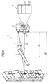
- FIG. 1 shows a recording device 1 for distance images.
- the recording device 1 comprises a laser light source 2 which transmits light pulses 3 to a foreground object 4 and a background object 5.
- the light pulses 6 thrown back by the foreground object 4 and by the background object 5 are detected by a camera 7, which comprises a light sensor 8 fabricated in CMOS technology with a multiplicity of sensor elements 9.
- the reflected light pulses 6 can both be reflected back and scattered back.
- the foreground object 4 is located at the distance d1 to the camera 7, while the background object 5 is at a distance d2 from the camera 7.
- the foreground object 4 and the background object 5 are imaged onto the sensor elements 9.
- the rest of the sensor element 9 is occupied by an image 12 of the background object 5.
- the relevant sensor element 9 therefore receives both light pulses coming from the foreground object 4 and light pulses which have been reflected by the background object 5.
- delayed light pulses 6 therefore arrive at different time intervals.
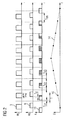
- FIG. 2 a sequence of light pulses 3 emitted by the laser light source 2, reflected-back light pulses 6 and a sequence of integration windows 13 and a correlation function 14 resulting from the measurement are shown in timing diagrams.
- the luminous fluxes ⁇ S are shown in each case.
- the luminous fluxes ⁇ R of the reflected light pulses 6 are shown in the time diagram which reflects the reflected light pulses 6.
- the thrown back light pulses 6 are delayed according to the time required for the path to the object and back to the camera 7 by a period of time T d .
- the sensor elements 9 are activated for the duration of the integration window 13.
- the integration windows 13 have a time duration T I 'and are shifted in the individual measuring operations in each case a time period T V0 to T VN .
- the integration of the luminous flux of the thrown back light pulse 6 finds only within the integration window 13 instead. In this case, the amount of light Q of the reflected light pulses 6 is determined, which strikes the respective sensor element 9 in the integration window 13.
- the light quantity values 15 are proportional to the charge quantity or voltage U read out of the sensor elements. The light quantity values 15 thus determined form a correlation curve 14.
- the maximum can, for example, be determined from the maximum Correlation curve 14, the delay due to the delay T d of the light pulse are determined. However, this presupposes that the integration duration T I of the integration window 13 is approximately equal to the pulse duration T PW of the light pulse 3.
- FIG. 3 Now the situation is shown that the emitted light pulse 3 is thrown back on the foreground 4 and the other on the background object 5 on the one hand. Therefore, two time-shifted light pulses 6 strike the sensor element 9.
- the sensor element 9 Only the second, reflected at the background object 5 light pulse 6 is detected by the sensor element 9, since at the time of arrival of the light reflected on the background object 5 light pulse 6, the relevant sensor element 9 is activated.
- the FIG. 3 illustrated timing diagrams relate to the delay time T V5 .
- FIG. 4 the situation is shown at the delay time T V7 .
- the time interval between the emitted light pulse 3 and the integration window 13 has been further shortened.
- the integration window 13 detects not only the reflected light pulse 6 at the background object 5, but at least partially also the light pulse 6 reflected at the foreground object 4.
- FIG. 5 the conditions at the delay time T V9 are shown.
- the time interval between the emitted light pulse 3 and the integration window 13 is now so small that both reflected light pulses 6 are within the integration window 13 and detected.
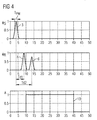
- FIG. 6 shows the resulting in the resolution of the individual reflected back light pulses 6 correlation curve 16.
- the correlation curve 16 has at the rising end between 0 and the delay time T V5 a stage 17 and between the delay time T V5 and the delay time T V9, a further stage 18. At the descending end, the correlation curve 16 has descending steps 19 and 20 corresponding to the rising steps 17 and 18. By detecting the reversal points of the steps 17 and 18 and also 19 and 20, the light transit time of the light pulses 6 reflected at the foreground object 4 and the background object 5 can be determined.
- the illustrated correlation curve 16 was recorded on the basis of a multiple scene with a foreground object 4 and background object 5, which were 150 cm apart, with a pulse width T PW of 2 ns and an integration time T I of 30 ns.
- the determination of the reversal points is advantageously carried out on the basis of a FIG. 7
- the rising levels 17 and 18 are assigned local maxima 22 and 23, respectively, while the falling steps 19 and 20 in the difference curve 21 each have a minimum 24 and 25 corresponds.
- the number and the distance of the extreme values of the difference curve 21 determine the number and the distance of the different object levels.
- FIG. 8 shows a block diagram of an operation of the recording device 1 from FIG. 1
- the circuit 26 includes a control unit 27, which acts on the laser light source 2 with a trigger signal 28.
- the trigger signal 28 is also sent through a delay unit 29 and controls the light sensor 8.
- the rising edge of the trigger signal 28 can be used to trigger in the laser light source 2 a light pulse 3, which is sent to a scene 30 to be examined is thrown back there and arrives at the light sensor 8 as reflected light pulse 6. While the trigger signal 28 assumes a high level, the light sensor 8 remains activated.
- the amount of charge generated in the individual sensor elements 9 is read out, digitized and stored in a buffer 31.
- An evaluation unit 32 connected downstream of the intermediate memory 31 then calculates the difference curve 21 on the basis of the correlation curve 16 stored in the intermediate memory 31. From the difference curve 21, the evaluation unit 32 can determine the number and the spacing of the image planes.
- the buffer 31 and the evaluation unit 32 are also supplied with control signals 33 from the control unit 27.
- FIG. 9 shows a block diagram of another circuit 34, which can be used for the recording device 1.
- the trigger signal 28 generated by the control unit 27 of the circuit 34 is guided at the circuit 34 on the way to the laser light source 2 via a delay unit 35. This is easily possible because ultimately it just matters that the time interval between the emission of the light pulses 3 by the laser light source 2 and the integration window 13 can be varied.
- the trigger signal 28 acts on the sensor elements 9, with pairs of adjacent sensor elements 9 operating in a delay unit 36 with time-shifted integration windows 13 due to a delay of the trigger signal 28.
- the evaluation unit 32 can then determine the number and the distance of the object planes on the basis of the position and the number of local extreme values.
- the same light pulse 6 is always integrated in both integration windows 13. This increases the accuracy of measurement, since the typical reset noise for CMOS technology-based light sensors 8 is largely eliminated.
- the variation of the pulse duration T PW of the light pulses 3 has no influence on the values of the difference curve 21.
- the pickup device 1 is also capable of detecting soils and moisture on the optical device.
- a protective glass is mounted in front of the laser light source 2 and the camera 7, through which both the light of the emitted light pulses 3 and the light pulses 6 reflected by the scene 30 pass. Dirt or moisture on the outside of the protective glass causes part of the emitted light pulse 3 to be thrown back towards the camera 7. The other part of the emitted light pulse, however, reaches the scene 30 and is reflected by the scene 30.
- the temporally successive incoming light pulses 6 can be detected on the basis of the correlation curve 16. This makes it possible to respond early to contamination or wetting of the optical device, for example by activating a cleaning device becomes.
- a cleaning device may be, for example, a windshield wiper or a blowing device, by means of which the function of the receiving device 1 can be maintained even under adverse environmental conditions.
- the recording device 1 it is possible with the recording device 1 to achieve a lateral spatial resolution, which is not limited by the lateral extent of the sensor elements 9.
- a lateral spatial resolution which is not limited by the lateral extent of the sensor elements 9.
- a distance image 38 of low resolution can be converted into a distance image 39 with increased resolution by dividing pixels 40 that represent multiple targets with multiple object planes and therefore can not be assigned a unique distance value and by allocating corresponding spacing values from adjacent pixels 41 to the partial areas ,
- the distance image is generated by adaptation to the known model. This is particularly advantageous in monitoring tasks when known moving objects are to be detected in three-dimensional space and the objects to be detected are partially hidden by other structures.
- the objects to be monitored can be detected by the multi-target recording device 1 despite a partial occlusion. Because the model knowledge can be used to assign the distance value from the actual object to a picture element.
- Such monitoring tasks represent, for example, the recognition that counting and the tracking of persons and vehicles.
- the platform monitoring can also represent such a monitoring task.
Landscapes
- Engineering & Computer Science (AREA)
- Physics & Mathematics (AREA)
- Computer Networks & Wireless Communication (AREA)
- General Physics & Mathematics (AREA)
- Radar, Positioning & Navigation (AREA)
- Remote Sensing (AREA)
- Electromagnetism (AREA)
- Optical Radar Systems And Details Thereof (AREA)
- Measurement Of Optical Distance (AREA)
Abstract
Claims (11)
- Dispositif destiné à enregistrer des images d'espacement comprenant une source de lumière (2) émettant des impulsions de lumière (3) et un capteur de lumière (8) doté d'une pluralité d'éléments capteurs (9), qui reçoivent des impulsions de lumière (6) renvoyées sur une zone d'objet (4, 5) étendue dans l'espace au moyen de fenêtres temporelles (13), dont l'espacement dans le temps par rapport à l'opération d'émission des impulsions de lumière (3) peut être modifié, et d'une unité d'analyse (32) montée en aval des éléments capteurs (9), unité à laquelle sert la formation d'une fonction de corrélation (14, 16) à partir de la lumière reçue sur l'élément capteur concerné dans différentes fenêtres temporelles pour déterminer des valeurs d'espacement par rapport à des zones d'objet (4, 5), caractérisé en ce que l'unité d'analyse (32) détermine des valeurs extrêmes de la pente (22 à 25) dans la fonction de corrélation (16), fonction de laquelle résultent les espacements de plusieurs zones d'objet (4, 5) éloignées différemment, et l'unité d'analyse (32) divise des éléments d'image (40), qui représentent plusieurs zones d'objet (4, 5) espacées différemment, et attribue les zones partielles aux éléments d'image (41, 42) voisins en fonction de leurs valeurs d'espacement.
- Dispositif selon la revendication 1, la durée des impulsions de lumière (3) émises étant inférieure au temps dont la lumière a besoin pour parcourir une différence d'espacement à résoudre.
- Dispositif selon la revendication 1 ou 2, l'espace de temps entre l'opération d'émission de l'impulsion lumineuse (3) et la fenêtre temporelle (13) pouvant être modifié de laps de temps qui sont inférieurs à la durée de demi-valeur des impulsions lumineuses (3) émises.
- Dispositif selon l'une des revendications 1 à 3, l'unité d'analyse (32) déterminant la position des valeurs extrêmes de la pente à l'aide de la dérivée (21) de la fonction de corrélation (16).
- Dispositif selon la revendication 4, la dérivée (21) contenant les différences entre une valeur définie de la fonction de corrélation (16) et une valeur voisine de la fonction de corrélation (16).
- Dispositif selon la revendication 5, l'espace de temps entre la valeur définie et la valeur voisine de la fonction de corrélation (16) étant inférieur à la double durée de demi-valeur des impulsions lumineuses (3) émises.
- Dispositif selon la revendication 5 ou 6, l'espace de temps entre la valeur définie et la valeur voisine de la fonction de corrélation (16) étant supérieur ou égal à la demi-durée de demi-valeur des impulsions lumineuses (3) émises.
- Dispositif selon l'une des revendications 1 à 7, le dispositif présentant une mémoire intermédiaire (31), dans laquelle les valeurs de la fonction de corrélation (16) pour le traitement par l'unité d'analyse (32) peuvent être déposées.
- Dispositif selon l'une des revendication 1 à 8, des éléments capteurs (9) voisins présentant des fenêtres temporelles (13) décalées à chaque fois par paires et une unité de formation de différence (37) montée en aval de la paire respective d'éléments capteurs (9) voisins, déterminant les valeurs de la dérivée (21).
- Procédé destiné à enregistrer des images d'espacement, dans lequel des impulsions lumineuses (6) renvoyées sur une zone d'objet (4, 5) étendue dans l'espace sont reçues à l'aide d'une source de lumière (2) émettant des impulsions lumineuses (3) et avec un capteur de lumière (8) doté d'une pluralité d'éléments capteurs (9) sur des fenêtres temporelles (13), dont l'espacement temporel par rapport à l'opération d'émission des impulsions de lumière (3) peut être modifié, et une fonction de corrélation (14, 16) étant formée à partir de la lumière reçue sur l'élément capteur respectif dans différentes fenêtres temporelles pour déterminer des valeurs d'espacement de zones d'objet (4, 5), caractérisé en ce que les espacements à des zones d'objet (4, 5) éloignées différemment sont déterminés à l'aide de valeurs extrêmes de la pente de la fonction de corrélation (16), et des éléments d'image (40), qui représentent plusieurs zones d'objet (4, 5) espacées différemment, sont divisés et les zones partielles sont attribuées aux éléments d'image (41, 42) voisins en fonction de leurs valeurs d'espacement.
- Procédé selon la revendication 10, les valeurs extrêmes de la pente de la fonction de corrélation (16) étant déterminées à l'aide de valeurs extrêmes d'une fonction de différence (21) déduite de la fonction de corrélation (16).
Applications Claiming Priority (2)
| Application Number | Priority Date | Filing Date | Title |
|---|---|---|---|
| DE102005046950A DE102005046950B3 (de) | 2005-09-30 | 2005-09-30 | Vorrichtung und Verfahren zur Aufnahme von Abstandsbildern |
| PCT/EP2006/066855 WO2007036557A1 (fr) | 2005-09-30 | 2006-09-28 | Procede et dispositif de prise de vue de distances |
Publications (2)
| Publication Number | Publication Date |
|---|---|
| EP1932017A1 EP1932017A1 (fr) | 2008-06-18 |
| EP1932017B1 true EP1932017B1 (fr) | 2012-05-16 |
Family
ID=37433652
Family Applications (1)
| Application Number | Title | Priority Date | Filing Date |
|---|---|---|---|
| EP06806876A Active EP1932017B1 (fr) | 2005-09-30 | 2006-09-28 | Procede et dispositif de prise de vue de distances |
Country Status (4)
| Country | Link |
|---|---|
| US (1) | US7791714B2 (fr) |
| EP (1) | EP1932017B1 (fr) |
| DE (1) | DE102005046950B3 (fr) |
| WO (1) | WO2007036557A1 (fr) |
Families Citing this family (7)
| Publication number | Priority date | Publication date | Assignee | Title |
|---|---|---|---|---|
| JP5804467B2 (ja) * | 2010-03-31 | 2015-11-04 | 北陽電機株式会社 | 信号処理装置、及び走査式測距装置 |
| DE102011010102B4 (de) * | 2011-02-01 | 2012-09-13 | Diehl Bgt Defence Gmbh & Co. Kg | Verfahren zum Messen einer Entfernung und Vorrichtung zur Durchführung des Verfahrens |
| JP5785753B2 (ja) * | 2011-03-25 | 2015-09-30 | 京セラ株式会社 | 電子機器、制御方法および制御プログラム |
| DE102014117097B3 (de) * | 2014-11-21 | 2016-01-21 | Odos Imaging Ltd. | Abstandsmessvorrichtung und Verfahren zum Bestimmen eines Abstands |
| JPWO2016208318A1 (ja) * | 2015-06-24 | 2018-04-19 | コニカミノルタ株式会社 | 距離画像処理装置、距離画像処理方法、距離画像処理プログラムおよび記録媒体 |
| WO2019064062A1 (fr) * | 2017-09-26 | 2019-04-04 | Innoviz Technologies Ltd. | Systèmes et procédés de détection et localisation par la lumière |
| CN110389351B (zh) * | 2018-04-16 | 2021-03-26 | 宁波飞芯电子科技有限公司 | Tof距离传感器、传感阵列及基于tof距离传感器的测距方法 |
Citations (1)
| Publication number | Priority date | Publication date | Assignee | Title |
|---|---|---|---|---|
| US4722599A (en) * | 1984-12-27 | 1988-02-02 | Frank Fruengel | Device for measuring cloud height |
Family Cites Families (5)
| Publication number | Priority date | Publication date | Assignee | Title |
|---|---|---|---|---|
| JPS62929A (ja) * | 1985-06-27 | 1987-01-06 | Matsushita Electric Ind Co Ltd | カメラの自動焦点調節装置 |
| JP3860412B2 (ja) * | 1997-12-23 | 2006-12-20 | シーメンス アクチエンゲゼルシヤフト | 3次元距離画像を撮影するための方法及び装置 |
| DE19833207A1 (de) | 1998-07-23 | 2000-02-17 | Siemens Ag | Verfahren und Vorrichtung zur Aufnahme eines dreidimensionalen Abstandsbildes |
| DE10116599A1 (de) * | 2001-04-03 | 2003-02-06 | Heidenhain Gmbh Dr Johannes | Optische Positionsmesseinrichtung |
| EP1423731B1 (fr) * | 2001-08-06 | 2006-10-04 | Siemens Aktiengesellschaft | Procede et dispositif pour acquerir une image telemetrique tridimensionnelle |
-
2005
- 2005-09-30 DE DE102005046950A patent/DE102005046950B3/de not_active Expired - Fee Related
-
2006
- 2006-09-28 US US11/991,981 patent/US7791714B2/en active Active
- 2006-09-28 EP EP06806876A patent/EP1932017B1/fr active Active
- 2006-09-28 WO PCT/EP2006/066855 patent/WO2007036557A1/fr active Application Filing
Patent Citations (1)
| Publication number | Priority date | Publication date | Assignee | Title |
|---|---|---|---|---|
| US4722599A (en) * | 1984-12-27 | 1988-02-02 | Frank Fruengel | Device for measuring cloud height |
Also Published As
| Publication number | Publication date |
|---|---|
| US7791714B2 (en) | 2010-09-07 |
| WO2007036557A1 (fr) | 2007-04-05 |
| US20090135405A1 (en) | 2009-05-28 |
| EP1932017A1 (fr) | 2008-06-18 |
| DE102005046950B3 (de) | 2006-12-21 |
Similar Documents
| Publication | Publication Date | Title |
|---|---|---|
| EP3418766B1 (fr) | Capteur optoélectronique et procédé de mesure de la distance par rapport à un objet | |
| EP1932017B1 (fr) | Procede et dispositif de prise de vue de distances | |
| EP2486370B1 (fr) | Télémètre optique avec dispositif d'étalonnage | |
| DE102017113675B4 (de) | Optoelektronischer Sensor und Verfahren zur Messung der Entfernung zu einem Objekt | |
| EP2541273B1 (fr) | Détection et détermination de distance d'objets | |
| DE4411713B4 (de) | Optische Entfernungsmeßvorrichtung und Verwendung derselben | |
| DE102016221049A1 (de) | Vorrichtung und Verfahren zum Empfangen eines reflektierten Lichtpulses in einem Lidar-System | |
| EP2558883B1 (fr) | Appareil de mesure de distance à évaluation de mesure à effet homogénéisant | |
| EP1722191B1 (fr) | Détermination de distance | |
| DE60313429T2 (de) | Dreidimensionales Bilderzeugungssytem | |
| EP0122609B1 (fr) | Méthode et dispositif pour contrôler l'énergie émise dans un appareil mesurant la hauteur des nuages | |
| EP2479586B1 (fr) | Procédé destiné à l'évaluation d'un degré d'impureté d'un disque frontal d'un dispositif de saisie optique et dispositif de saisie optique | |
| EP1303768B1 (fr) | Procede pour determiner la distance de visibilite | |
| DE202013101039U1 (de) | Optoelektronischer Sensor zur Entfernungsmessung | |
| DE10353348A1 (de) | Verfahren zur Verfolgung von Objekten | |
| DE102015217912A1 (de) | Verfahren zur Laufzeitkalibrierung eines Lidarsensors | |
| DE102014117705B3 (de) | Abstandsmessvorrichtung und Verfahren zum Bestimmen eines Abstands | |
| DE4005919C2 (de) | Verfahren und Anordnung zum Ermitteln der Sichtweite für Autofahrer beim Auftreten von Nebel | |
| DE3030229A1 (de) | Verfahren zur erkennung und identifikation von sich bewegenden objekten sowie zur ermittlung ihrer geschwindigkeit | |
| EP3602124A1 (fr) | Système lidar à base de spad (photodiodes avalanche à photon unique) | |
| EP3671276B1 (fr) | Capteur optoélectronique et procédé de détection d'un objet | |
| DE102004026090A1 (de) | Messsystem zur dreidimensionalen Bilderfassung | |
| EP3994481A1 (fr) | Dispositif de lecture et dispositif de mesure lidar | |
| DE602004003912T2 (de) | Vorrichtung und Verfahren zur Messung der Sichtweite | |
| DE102015004903A1 (de) | Optoelektronische Messvorrichtung |
Legal Events
| Date | Code | Title | Description |
|---|---|---|---|
| PUAI | Public reference made under article 153(3) epc to a published international application that has entered the european phase |
Free format text: ORIGINAL CODE: 0009012 |
|
| 17P | Request for examination filed |
Effective date: 20080307 |
|
| AK | Designated contracting states |
Kind code of ref document: A1 Designated state(s): DE FR IT |
|
| 17Q | First examination report despatched |
Effective date: 20080707 |
|
| DAX | Request for extension of the european patent (deleted) | ||
| RBV | Designated contracting states (corrected) |
Designated state(s): DE FR IT |
|
| RAP1 | Party data changed (applicant data changed or rights of an application transferred) |
Owner name: ODOS IMAGING LTD |
|
| REG | Reference to a national code |
Ref country code: DE Ref legal event code: R079 Ref document number: 502006011459 Country of ref document: DE Free format text: PREVIOUS MAIN CLASS: G01S0017100000 Ipc: G01S0007487000 |
|
| GRAP | Despatch of communication of intention to grant a patent |
Free format text: ORIGINAL CODE: EPIDOSNIGR1 |
|
| RIC1 | Information provided on ipc code assigned before grant |
Ipc: G01S 7/487 20060101AFI20111208BHEP Ipc: G01S 17/10 20060101ALI20111208BHEP Ipc: G01S 17/89 20060101ALI20111208BHEP Ipc: G01S 7/497 20060101ALI20111208BHEP |
|
| GRAS | Grant fee paid |
Free format text: ORIGINAL CODE: EPIDOSNIGR3 |
|
| GRAA | (expected) grant |
Free format text: ORIGINAL CODE: 0009210 |
|
| AK | Designated contracting states |
Kind code of ref document: B1 Designated state(s): DE FR IT |
|
| REG | Reference to a national code |
Ref country code: DE Ref legal event code: R096 Ref document number: 502006011459 Country of ref document: DE Effective date: 20120712 |
|
| PLBE | No opposition filed within time limit |
Free format text: ORIGINAL CODE: 0009261 |
|
| STAA | Information on the status of an ep patent application or granted ep patent |
Free format text: STATUS: NO OPPOSITION FILED WITHIN TIME LIMIT |
|
| 26N | No opposition filed |
Effective date: 20130219 |
|
| REG | Reference to a national code |
Ref country code: DE Ref legal event code: R097 Ref document number: 502006011459 Country of ref document: DE Effective date: 20130219 |
|
| REG | Reference to a national code |
Ref country code: FR Ref legal event code: PLFP Year of fee payment: 11 |
|
| REG | Reference to a national code |
Ref country code: FR Ref legal event code: PLFP Year of fee payment: 12 |
|
| REG | Reference to a national code |
Ref country code: FR Ref legal event code: PLFP Year of fee payment: 13 |
|
| REG | Reference to a national code |
Ref country code: DE Ref legal event code: R082 Ref document number: 502006011459 Country of ref document: DE Representative=s name: GRUENECKER PATENT- UND RECHTSANWAELTE PARTG MB, DE |
|
| P01 | Opt-out of the competence of the unified patent court (upc) registered |
Effective date: 20230404 |
|
| PGFP | Annual fee paid to national office [announced via postgrant information from national office to epo] |
Ref country code: IT Payment date: 20230822 Year of fee payment: 18 |
|
| PGFP | Annual fee paid to national office [announced via postgrant information from national office to epo] |
Ref country code: FR Payment date: 20230822 Year of fee payment: 18 Ref country code: DE Payment date: 20230822 Year of fee payment: 18 |