EP1932017B1 - Device and method for recording distance images - Google Patents
Device and method for recording distance images Download PDFInfo
- Publication number
- EP1932017B1 EP1932017B1 EP06806876A EP06806876A EP1932017B1 EP 1932017 B1 EP1932017 B1 EP 1932017B1 EP 06806876 A EP06806876 A EP 06806876A EP 06806876 A EP06806876 A EP 06806876A EP 1932017 B1 EP1932017 B1 EP 1932017B1
- Authority
- EP
- European Patent Office
- Prior art keywords
- light
- correlation function
- light pulses
- time
- values
- Prior art date
- Legal status (The legal status is an assumption and is not a legal conclusion. Google has not performed a legal analysis and makes no representation as to the accuracy of the status listed.)
- Active
Links
- 238000000034 method Methods 0.000 title claims description 16
- 238000005314 correlation function Methods 0.000 claims abstract description 26
- 230000006870 function Effects 0.000 claims description 7
- 238000003384 imaging method Methods 0.000 claims 2
- 230000010354 integration Effects 0.000 description 24
- 238000010586 diagram Methods 0.000 description 12
- 238000005516 engineering process Methods 0.000 description 5
- 238000011156 evaluation Methods 0.000 description 5
- 230000004907 flux Effects 0.000 description 5
- 238000012544 monitoring process Methods 0.000 description 5
- 230000000630 rising effect Effects 0.000 description 4
- 230000003111 delayed effect Effects 0.000 description 3
- 238000005259 measurement Methods 0.000 description 3
- 230000006978 adaptation Effects 0.000 description 2
- 238000004140 cleaning Methods 0.000 description 2
- 238000001514 detection method Methods 0.000 description 2
- 239000011521 glass Substances 0.000 description 2
- 230000003287 optical effect Effects 0.000 description 2
- 230000001681 protective effect Effects 0.000 description 2
- 238000012935 Averaging Methods 0.000 description 1
- 230000003213 activating effect Effects 0.000 description 1
- 230000002411 adverse Effects 0.000 description 1
- 238000007664 blowing Methods 0.000 description 1
- 239000002800 charge carrier Substances 0.000 description 1
- 238000011109 contamination Methods 0.000 description 1
- 230000001419 dependent effect Effects 0.000 description 1
- 238000009795 derivation Methods 0.000 description 1
- 238000011161 development Methods 0.000 description 1
- 230000018109 developmental process Effects 0.000 description 1
- 239000000428 dust Substances 0.000 description 1
- 230000007613 environmental effect Effects 0.000 description 1
- 239000002689 soil Substances 0.000 description 1
- 238000009736 wetting Methods 0.000 description 1
Images


Classifications
-
- G—PHYSICS
- G01—MEASURING; TESTING
- G01S—RADIO DIRECTION-FINDING; RADIO NAVIGATION; DETERMINING DISTANCE OR VELOCITY BY USE OF RADIO WAVES; LOCATING OR PRESENCE-DETECTING BY USE OF THE REFLECTION OR RERADIATION OF RADIO WAVES; ANALOGOUS ARRANGEMENTS USING OTHER WAVES
- G01S17/00—Systems using the reflection or reradiation of electromagnetic waves other than radio waves, e.g. lidar systems
- G01S17/88—Lidar systems specially adapted for specific applications
- G01S17/89—Lidar systems specially adapted for specific applications for mapping or imaging
-
- G—PHYSICS
- G01—MEASURING; TESTING
- G01S—RADIO DIRECTION-FINDING; RADIO NAVIGATION; DETERMINING DISTANCE OR VELOCITY BY USE OF RADIO WAVES; LOCATING OR PRESENCE-DETECTING BY USE OF THE REFLECTION OR RERADIATION OF RADIO WAVES; ANALOGOUS ARRANGEMENTS USING OTHER WAVES
- G01S17/00—Systems using the reflection or reradiation of electromagnetic waves other than radio waves, e.g. lidar systems
- G01S17/02—Systems using the reflection of electromagnetic waves other than radio waves
- G01S17/06—Systems determining position data of a target
- G01S17/08—Systems determining position data of a target for measuring distance only
- G01S17/10—Systems determining position data of a target for measuring distance only using transmission of interrupted, pulse-modulated waves
- G01S17/18—Systems determining position data of a target for measuring distance only using transmission of interrupted, pulse-modulated waves wherein range gates are used
-
- G—PHYSICS
- G01—MEASURING; TESTING
- G01S—RADIO DIRECTION-FINDING; RADIO NAVIGATION; DETERMINING DISTANCE OR VELOCITY BY USE OF RADIO WAVES; LOCATING OR PRESENCE-DETECTING BY USE OF THE REFLECTION OR RERADIATION OF RADIO WAVES; ANALOGOUS ARRANGEMENTS USING OTHER WAVES
- G01S7/00—Details of systems according to groups G01S13/00, G01S15/00, G01S17/00
- G01S7/48—Details of systems according to groups G01S13/00, G01S15/00, G01S17/00 of systems according to group G01S17/00
- G01S7/483—Details of pulse systems
- G01S7/486—Receivers
- G01S7/4865—Time delay measurement, e.g. time-of-flight measurement, time of arrival measurement or determining the exact position of a peak
-
- G—PHYSICS
- G01—MEASURING; TESTING
- G01S—RADIO DIRECTION-FINDING; RADIO NAVIGATION; DETERMINING DISTANCE OR VELOCITY BY USE OF RADIO WAVES; LOCATING OR PRESENCE-DETECTING BY USE OF THE REFLECTION OR RERADIATION OF RADIO WAVES; ANALOGOUS ARRANGEMENTS USING OTHER WAVES
- G01S7/00—Details of systems according to groups G01S13/00, G01S15/00, G01S17/00
- G01S7/48—Details of systems according to groups G01S13/00, G01S15/00, G01S17/00 of systems according to group G01S17/00
- G01S7/483—Details of pulse systems
- G01S7/486—Receivers
- G01S7/487—Extracting wanted echo signals, e.g. pulse detection
-
- G—PHYSICS
- G01—MEASURING; TESTING
- G01S—RADIO DIRECTION-FINDING; RADIO NAVIGATION; DETERMINING DISTANCE OR VELOCITY BY USE OF RADIO WAVES; LOCATING OR PRESENCE-DETECTING BY USE OF THE REFLECTION OR RERADIATION OF RADIO WAVES; ANALOGOUS ARRANGEMENTS USING OTHER WAVES
- G01S7/00—Details of systems according to groups G01S13/00, G01S15/00, G01S17/00
- G01S7/48—Details of systems according to groups G01S13/00, G01S15/00, G01S17/00 of systems according to group G01S17/00
- G01S7/497—Means for monitoring or calibrating
- G01S2007/4975—Means for monitoring or calibrating of sensor obstruction by, e.g. dirt- or ice-coating, e.g. by reflection measurement on front-screen
Definitions
- the invention relates to a device for recording distance images with a light pulse emitting light source and a light receiver, which integrates the light flow of a light pulse over a time window whose time interval is variable to the emission of a light pulse to a plurality of light quantity values, and with a the evaluation unit connected downstream of the light receiver, which determines the distance of the object area on the basis of the correlation function formed by the light quantity values.
- the invention further relates to a method for recording distance images, in which a correlation function between a light pulse reflected back at an object area and a time window of the light transit time measuring device is determined with the aid of a light-time measuring device with short-time integration.
- Such a device and method are known from WO 03/016944 A2 known.
- light pulses are transmitted from a light source to an object surface and thrown back there.
- the light reflected back on the object surface passes to a CMOS imager which has a plurality of light receivers in which the incident light flux can generate charge carriers when the light receiver is activated.
- the light receivers can be activated during a variable time window.
- the amount of charge present in the light receiver at the end of the time window is a measure of the amount of light that has been detected by the light receiver during the time window.
- the light receiver therefore integrates the incident luminous flux during the time window.
- a correlation function between the light pulse and the time window can be determined. If the duration of the light pulses is equal to the duration of the time window, the correlation function has a pronounced maximum. The maximum of the correlation function is at a time value corresponding to the light transit time of the light pulse from the light source to the light receiver. Therefore, from the maximum of the correlation function directly the light transit time can be determined. The distance between the object surface and the device can then be calculated from the light transit time.
- the known device and the known method can be used in the field of automotive technology, navigation or building, safety and automation technology.
- a disadvantage of the known device and the known method is that partially concealed objects, for example a vehicle behind a fence or a shrubbery, are not recognized correctly. Likewise, dust or other dirt on the optics can lead to incorrect measurements. Because in the known method and the known device in partially concealed objects, a mean distance value is displayed, which results from the averaging of different distance values.
- a cloud altimeter is described in which the output signals of a light receiver are integrated in a time window, wherein the time window is shifted stepwise relative to the emitted light pulses.
- a cloud altimeter microprocessor forms a smoothed function of the signals, derives the function and calculates maxima and minima.
- the invention is therefore the object of an apparatus and a method to create distance images that are multi-objective.
- extreme values of the slope in the correlation function are determined and from these the distances of differently removed object areas are determined. Because light pulses, which are reflected at differently distant object areas, arrive delayed at the respective light receiver. They therefore only contribute to the light quantity signal if the respective light pulse lies in the respective time window used. A stepwise increase in the correlation function can therefore be attributed to the detection of additional light pulses. The light transit time of the light pulses reflected at different object areas can then be determined from the slope maxima. In this respect, the device and the method are multi-target capable.
- the duration of the light pulses emitted by the light source is chosen to be less than or equal to the light transit time for a distance difference to be resolved.
- the duration of the light pulses should be understood to mean the half-life of the light pulses. With this duration of the light pulses, it is possible to resolve the desired distance distance.
- the slope maxima are preferably determined on the basis of a derivative function of the correlation function. In this case, the determination of the slope maxima can be attributed to a search of local extreme values.
- the slope function is preferably determined by determining the difference between two light quantity values having a time interval in the range of the pulse duration. This reduces the susceptibility to noise and noise typical of calculating a derivative function.
- the light quantity values recorded by a light receiver can be temporarily stored in a buffer.
- the derivation can then be calculated on the basis of the light quantity values stored in the buffer.
- all light receivers may be directed to different object areas and thus contribute to the full spatial resolution.
- the additional location information is used to increase the spatial resolution of the distance image.
- the distance values of the neighboring picture elements of the distance picture can be used for this purpose by assigning different distance values to sub-areas of a picture element corresponding to the distance values of the neighboring picture elements.
- the distance image can be generated by adaptation to the known object. This is particularly advantageous in monitoring tasks when known objects in motion are to be detected and the objects to be detected are partially covered by other structures.
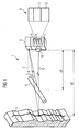
- FIG. 1 shows a recording device 1 for distance images.
- the recording device 1 comprises a laser light source 2 which transmits light pulses 3 to a foreground object 4 and a background object 5.
- the light pulses 6 thrown back by the foreground object 4 and by the background object 5 are detected by a camera 7, which comprises a light sensor 8 fabricated in CMOS technology with a multiplicity of sensor elements 9.
- the reflected light pulses 6 can both be reflected back and scattered back.
- the foreground object 4 is located at the distance d1 to the camera 7, while the background object 5 is at a distance d2 from the camera 7.
- the foreground object 4 and the background object 5 are imaged onto the sensor elements 9.
- the rest of the sensor element 9 is occupied by an image 12 of the background object 5.
- the relevant sensor element 9 therefore receives both light pulses coming from the foreground object 4 and light pulses which have been reflected by the background object 5.
- delayed light pulses 6 therefore arrive at different time intervals.
- FIG. 2 a sequence of light pulses 3 emitted by the laser light source 2, reflected-back light pulses 6 and a sequence of integration windows 13 and a correlation function 14 resulting from the measurement are shown in timing diagrams.
- the luminous fluxes ⁇ S are shown in each case.
- the luminous fluxes ⁇ R of the reflected light pulses 6 are shown in the time diagram which reflects the reflected light pulses 6.
- the thrown back light pulses 6 are delayed according to the time required for the path to the object and back to the camera 7 by a period of time T d .
- the sensor elements 9 are activated for the duration of the integration window 13.
- the integration windows 13 have a time duration T I 'and are shifted in the individual measuring operations in each case a time period T V0 to T VN .
- the integration of the luminous flux of the thrown back light pulse 6 finds only within the integration window 13 instead. In this case, the amount of light Q of the reflected light pulses 6 is determined, which strikes the respective sensor element 9 in the integration window 13.
- the light quantity values 15 are proportional to the charge quantity or voltage U read out of the sensor elements. The light quantity values 15 thus determined form a correlation curve 14.
- the maximum can, for example, be determined from the maximum Correlation curve 14, the delay due to the delay T d of the light pulse are determined. However, this presupposes that the integration duration T I of the integration window 13 is approximately equal to the pulse duration T PW of the light pulse 3.
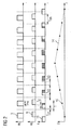
- FIG. 3 Now the situation is shown that the emitted light pulse 3 is thrown back on the foreground 4 and the other on the background object 5 on the one hand. Therefore, two time-shifted light pulses 6 strike the sensor element 9.
- the sensor element 9 Only the second, reflected at the background object 5 light pulse 6 is detected by the sensor element 9, since at the time of arrival of the light reflected on the background object 5 light pulse 6, the relevant sensor element 9 is activated.
- the FIG. 3 illustrated timing diagrams relate to the delay time T V5 .
- FIG. 4 the situation is shown at the delay time T V7 .
- the time interval between the emitted light pulse 3 and the integration window 13 has been further shortened.
- the integration window 13 detects not only the reflected light pulse 6 at the background object 5, but at least partially also the light pulse 6 reflected at the foreground object 4.
- FIG. 5 the conditions at the delay time T V9 are shown.
- the time interval between the emitted light pulse 3 and the integration window 13 is now so small that both reflected light pulses 6 are within the integration window 13 and detected.
- FIG. 6 shows the resulting in the resolution of the individual reflected back light pulses 6 correlation curve 16.
- the correlation curve 16 has at the rising end between 0 and the delay time T V5 a stage 17 and between the delay time T V5 and the delay time T V9, a further stage 18. At the descending end, the correlation curve 16 has descending steps 19 and 20 corresponding to the rising steps 17 and 18. By detecting the reversal points of the steps 17 and 18 and also 19 and 20, the light transit time of the light pulses 6 reflected at the foreground object 4 and the background object 5 can be determined.
- the illustrated correlation curve 16 was recorded on the basis of a multiple scene with a foreground object 4 and background object 5, which were 150 cm apart, with a pulse width T PW of 2 ns and an integration time T I of 30 ns.
- the determination of the reversal points is advantageously carried out on the basis of a FIG. 7
- the rising levels 17 and 18 are assigned local maxima 22 and 23, respectively, while the falling steps 19 and 20 in the difference curve 21 each have a minimum 24 and 25 corresponds.
- the number and the distance of the extreme values of the difference curve 21 determine the number and the distance of the different object levels.
- FIG. 8 shows a block diagram of an operation of the recording device 1 from FIG. 1
- the circuit 26 includes a control unit 27, which acts on the laser light source 2 with a trigger signal 28.
- the trigger signal 28 is also sent through a delay unit 29 and controls the light sensor 8.
- the rising edge of the trigger signal 28 can be used to trigger in the laser light source 2 a light pulse 3, which is sent to a scene 30 to be examined is thrown back there and arrives at the light sensor 8 as reflected light pulse 6. While the trigger signal 28 assumes a high level, the light sensor 8 remains activated.
- the amount of charge generated in the individual sensor elements 9 is read out, digitized and stored in a buffer 31.
- An evaluation unit 32 connected downstream of the intermediate memory 31 then calculates the difference curve 21 on the basis of the correlation curve 16 stored in the intermediate memory 31. From the difference curve 21, the evaluation unit 32 can determine the number and the spacing of the image planes.
- the buffer 31 and the evaluation unit 32 are also supplied with control signals 33 from the control unit 27.
- FIG. 9 shows a block diagram of another circuit 34, which can be used for the recording device 1.
- the trigger signal 28 generated by the control unit 27 of the circuit 34 is guided at the circuit 34 on the way to the laser light source 2 via a delay unit 35. This is easily possible because ultimately it just matters that the time interval between the emission of the light pulses 3 by the laser light source 2 and the integration window 13 can be varied.
- the trigger signal 28 acts on the sensor elements 9, with pairs of adjacent sensor elements 9 operating in a delay unit 36 with time-shifted integration windows 13 due to a delay of the trigger signal 28.
- the evaluation unit 32 can then determine the number and the distance of the object planes on the basis of the position and the number of local extreme values.
- the same light pulse 6 is always integrated in both integration windows 13. This increases the accuracy of measurement, since the typical reset noise for CMOS technology-based light sensors 8 is largely eliminated.
- the variation of the pulse duration T PW of the light pulses 3 has no influence on the values of the difference curve 21.
- the pickup device 1 is also capable of detecting soils and moisture on the optical device.
- a protective glass is mounted in front of the laser light source 2 and the camera 7, through which both the light of the emitted light pulses 3 and the light pulses 6 reflected by the scene 30 pass. Dirt or moisture on the outside of the protective glass causes part of the emitted light pulse 3 to be thrown back towards the camera 7. The other part of the emitted light pulse, however, reaches the scene 30 and is reflected by the scene 30.
- the temporally successive incoming light pulses 6 can be detected on the basis of the correlation curve 16. This makes it possible to respond early to contamination or wetting of the optical device, for example by activating a cleaning device becomes.
- a cleaning device may be, for example, a windshield wiper or a blowing device, by means of which the function of the receiving device 1 can be maintained even under adverse environmental conditions.
- the recording device 1 it is possible with the recording device 1 to achieve a lateral spatial resolution, which is not limited by the lateral extent of the sensor elements 9.
- a lateral spatial resolution which is not limited by the lateral extent of the sensor elements 9.
- a distance image 38 of low resolution can be converted into a distance image 39 with increased resolution by dividing pixels 40 that represent multiple targets with multiple object planes and therefore can not be assigned a unique distance value and by allocating corresponding spacing values from adjacent pixels 41 to the partial areas ,
- the distance image is generated by adaptation to the known model. This is particularly advantageous in monitoring tasks when known moving objects are to be detected in three-dimensional space and the objects to be detected are partially hidden by other structures.
- the objects to be monitored can be detected by the multi-target recording device 1 despite a partial occlusion. Because the model knowledge can be used to assign the distance value from the actual object to a picture element.
- Such monitoring tasks represent, for example, the recognition that counting and the tracking of persons and vehicles.
- the platform monitoring can also represent such a monitoring task.
Abstract
Description
Die Erfindung betrifft eine Vorrichtung zur Aufnahme von Abstandbildern mit einer Lichtpulse aussendenden Lichtquelle und einem Lichtempfänger, der den an einem Objektbereich zugeworfenen Lichtstrom eines Lichtpulses über ein Zeitfenster, dessen Zeitabstand zum Aussendevorgang eines Lichtpulses variierbar ist, zu einer Vielzahl von Lichtmengenwerte integriert, und mit einer dem Lichtempfänger nachgeschalteten Auswerteeinheit, die anhand der von den Lichtmengenwerte gebildeten Korrelationsfunktion den Abstand des Objektbereichs ermittelt.The invention relates to a device for recording distance images with a light pulse emitting light source and a light receiver, which integrates the light flow of a light pulse over a time window whose time interval is variable to the emission of a light pulse to a plurality of light quantity values, and with a the evaluation unit connected downstream of the light receiver, which determines the distance of the object area on the basis of the correlation function formed by the light quantity values.
Die Erfindung betrifft ferner ein Verfahren zur Aufnahme von Abstandsbildern, bei dem mit Hilfe einer Lichtlaufmessvorrichtung mit Kurzzeitintegration eine Korrelationsfunktion zwischen einem an einem Objektbereich zurückgeworfenen Lichtpuls und einem Zeitfenster der Lichtlaufzeitmessvorrichtung bestimmt wird.The invention further relates to a method for recording distance images, in which a correlation function between a light pulse reflected back at an object area and a time window of the light transit time measuring device is determined with the aid of a light-time measuring device with short-time integration.
Eine derartige Vorrichtung und derartiges Verfahren sind aus der
Durch Variation des Zeitabstands zwischen dem Aussendevorgang des Lichtpulses und des zur Integration verwendeten Zeitfensters kann eine Korrelationsfunktion zwischen dem Lichtpuls und dem Zeitfenster bestimmt werden. Wenn die Dauer der Lichtpulse gleich der Dauer des Zeitfensters ist, weist die Korrelationsfunktion ein ausgeprägtes Maximum auf. Das Maximum der Korrelationsfunktion liegt bei einem Zeitwert, der der Lichtlaufzeit des Lichtpulses von der Lichtquelle zum Lichtempfänger entspricht. Daher kann aus dem Maximum der Korrelationsfunktion unmittelbar die Lichtlaufzeit bestimmt werden. Aus der Lichtlaufzeit kann dann der Abstand zwischen Objektoberfläche und Vorrichtung berechnet werden.By varying the time interval between the emission of the light pulse and the time window used for integration, a correlation function between the light pulse and the time window can be determined. If the duration of the light pulses is equal to the duration of the time window, the correlation function has a pronounced maximum. The maximum of the correlation function is at a time value corresponding to the light transit time of the light pulse from the light source to the light receiver. Therefore, from the maximum of the correlation function directly the light transit time can be determined. The distance between the object surface and the device can then be calculated from the light transit time.
Die bekannte Vorrichtung und das bekannte Verfahren können im Bereich der Automobiltechnik, der Navigation oder der Gebäude-, Sicherheits- und Automatisierungstechnik verwendet werden.The known device and the known method can be used in the field of automotive technology, navigation or building, safety and automation technology.
Ein Nachteil der bekannten Vorrichtung und des bekannten Verfahrens ist, dass teilverdeckt liegende Objekte, zum Beispiel ein Fahrzeug hinter einem Zaun oder einem Gebüsch, nicht richtig erkannt werden. Ebenso können Staub oder sonstige Verschmutzungen auf der Optik zu Fehlmessungen führen. Denn bei dem bekannten Verfahren und der bekannten Vorrichtung wird bei teilverdeckt liegenden Objekten ein mittlerer Abstandswert angezeigt, der sich aus der Mittelung verschiedener Entfernungswerte ergibt.A disadvantage of the known device and the known method is that partially concealed objects, for example a vehicle behind a fence or a shrubbery, are not recognized correctly. Likewise, dust or other dirt on the optics can lead to incorrect measurements. Because in the known method and the known device in partially concealed objects, a mean distance value is displayed, which results from the averaging of different distance values.
In
Ausgehend von diesem Stand der Technik liegt der Erfindung daher die Aufgabe zugrunde, eine Vorrichtung und ein Verfahren zur Aufnahme von Abstandsbildern zu schaffen, die mehrzielfähig sind.Based on this prior art, the invention is therefore the object of an apparatus and a method to create distance images that are multi-objective.
Diese Aufgabe wird durch eine Vorrichtung und ein Verfahren mit den Merkmalen der unabhängigen Ansprüche gelöst. In den davon abhängigen Ansprüchen sind vorteilhafte Ausgestaltungen und Weiterbildungen angegeben.This object is achieved by an apparatus and a method having the features of the independent claims. In the dependent claims advantageous embodiments and developments are given.
Bei der Vorrichtung und dem Verfahren werden Extremwerte der Steigung in der Korrelationsfunktion bestimmt und daraus die Abstände von unterschiedlich entfernten Objektbereichen ermittelt. Denn Lichtpulse, die an unterschiedlich entfernten Objektbereichen reflektiert werden, treffen verzögert am jeweiligen Lichtempfänger ein. Sie tragen daher nur dann zum Lichtmengensignal bei, wenn der jeweilige Lichtpuls im jeweils verwendetem Zeitfenster liegt. Ein stufenförmiges Ansteigen der Korrelationsfunktion kann daher auf das Erfassen zusätzlicher Lichtpulse zurückgeführt werden. Aus den Steigungsmaxima kann dann die Lichtlaufzeit der an unterschiedlichen Objektbereichen zurückgeworfenen Lichtpulse bestimmt werden. Insofern sind die Vorrichtung und das Verfahren mehrzielfähig.In the device and the method, extreme values of the slope in the correlation function are determined and from these the distances of differently removed object areas are determined. Because light pulses, which are reflected at differently distant object areas, arrive delayed at the respective light receiver. They therefore only contribute to the light quantity signal if the respective light pulse lies in the respective time window used. A stepwise increase in the correlation function can therefore be attributed to the detection of additional light pulses. The light transit time of the light pulses reflected at different object areas can then be determined from the slope maxima. In this respect, the device and the method are multi-target capable.
Bei einer bevorzugten Ausführungsform wird die Dauer der von der Lichtquelle ausgesandten Lichtpulse kleiner gleich der Lichtlaufzeit für einen aufzulösenden Entfernungsunterschied gewählt. Unter der Dauer der Lichtpulse soll dabei die Halbwertsdauer der Lichtpulse verstanden werden. Bei dieser Dauer der Lichtpulse ist es möglich, den gewünschten Entfernungsabstand aufzulösen.In a preferred embodiment, the duration of the light pulses emitted by the light source is chosen to be less than or equal to the light transit time for a distance difference to be resolved. The duration of the light pulses should be understood to mean the half-life of the light pulses. With this duration of the light pulses, it is possible to resolve the desired distance distance.
Weiterhin werden die Steigungsmaxima vorzugsweise anhand einer Ableitungsfunktion der Korrelationsfunktion bestimmt. In diesem Fall kann die Bestimmung der Steigungsmaxima auf eine Suche von lokalen Extremwerten zurückgeführt werden.Furthermore, the slope maxima are preferably determined on the basis of a derivative function of the correlation function. In this case, the determination of the slope maxima can be attributed to a search of local extreme values.
Die Steigungsfunktion wird vorzugsweise bestimmt, indem die Differenz zwischen zwei Lichtmengenwerten bestimmt wird, die einen Zeitabstand im Bereich der Pulsdauer aufweisen. Dadurch wird die für eine Berechnung einer Ableitungsfunktion typische Anfälligkeit gegenüber Störungen und Rauschen reduziert.The slope function is preferably determined by determining the difference between two light quantity values having a time interval in the range of the pulse duration. This reduces the susceptibility to noise and noise typical of calculating a derivative function.
Die von einem Lichtempfänger aufgenommenen Lichtmengenwerte können in einem Zwischenspeicher zwischengespeichert werden. Die Berechnung der Ableitung kann dann anhand der im Zwischenspeicher gespeicherten Lichtmengenwerte erfolgen. Bei einer derartigen Ausführungsform können sämtliche Lichtempfänger auf unterschiedliche Objektbereiche gerichtet sein und damit zur vollen räumlichen Auflösung beitragen.The light quantity values recorded by a light receiver can be temporarily stored in a buffer. The derivation can then be calculated on the basis of the light quantity values stored in the buffer. at Such an embodiment, all light receivers may be directed to different object areas and thus contribute to the full spatial resolution.
Bei einer weiteren abgewandelten Ausführungsform werden jeweils zwei benachbarte Lichtempfänger mit versetzten Zeitfenstern betrieben und jeweils der Differenzwert ausgelesen. Diese Ausführungsform bietet den Vorteil, dass die Variation der Lichtpulse keinen Einfluss auf das Differenzsignal hat. Außerdem wird das für in CMOS-Technik hergestellte Lichtempfänger typische Reset-Rauschen weitgehend eliminiert.In a further modified embodiment, in each case two adjacent light receivers are operated with offset time windows and in each case the difference value is read out. This embodiment offers the advantage that the variation of the light pulses has no influence on the difference signal. In addition, the reset noise typical of photoreceivers fabricated in CMOS technology is largely eliminated.
Gemäß der Erfindung wird die zusätzliche Ortsinformation dazu verwendet, die räumliche Auflösung des Abstandsbildes zu erhöhen. Bei unbekannten Objekten können dazu die Abstandswerte der benachbarten Bildelemente des Abstandsbildes herangezogen werden, indem Teilbereichen eines Bildelements entsprechend den Abstandswerten der benachbarten Bildelemente unterschiedliche Abstandswerte zugewiesen werden.According to the invention, the additional location information is used to increase the spatial resolution of the distance image. In the case of unknown objects, the distance values of the neighboring picture elements of the distance picture can be used for this purpose by assigning different distance values to sub-areas of a picture element corresponding to the distance values of the neighboring picture elements.
Bei bekannten Objekten kann das Abstandsbild durch Anpassung an das bekannte Objekt erzeugt werden. Dies ist insbesondere bei Überwachungsaufgaben vorteilhaft, wenn sich in Bewegung befindende bekannte Objekte detektiert werden sollen und die zu detektierenden Objekte durch andere Strukturen teilweise verdeckt sind.For known objects, the distance image can be generated by adaptation to the known object. This is particularly advantageous in monitoring tasks when known objects in motion are to be detected and the objects to be detected are partially covered by other structures.
Weitere Vorteile und Eigenschaften der Erfindung gehen aus der nachfolgenden Beschreibung hervor, in der Ausführungsbeispiele der Erfindung im Einzelnen anhand der beigefügten Zeichnung erläutert werden. Es zeigen:
Figur 1- eine Ansicht einer Vorrichtung zur Erzeugung von Abstandsbildern;
Figur 2- zeitliche Diagramme der Lichtpulse, der zur Integration verwendeten Zeitfenster und der zurückge- worfenen Lichtpulse einschließlich der vom Sensor erfassten Anteile sowie eine Darstellung einer Korrelationsfunktion;
Figur 3- Zeitdiagramme mit dem ausgesendeten Lichtpuls,zwei zurückgeworfenen Lichtpulsen und einem Integrationsfenster, das einen der beiden zurückgeworfenen Lichtpulse erfasst;
Figur 4- Zeitdiagramme entsprechend
Figur 3 Figur 5- Zeitdiagrammen entsprechend
Figur 3 Figur 6- eine Darstellung einer Korrelationsfunktion bei Vorliegen von zwei zurückgeworfenen Lichtpulsen;
Figur 7- die Ableitung der Korrelationsfunktion aus
Figur 6 - Figur 8
- ein Blockschaltbild einer Vorrichtung zur Aufnahme von Abstandsbildern;
Figur 9- ein Blockschaltbild einer weiteren Vorrichtung zur Aufnahme von Abstandsbildern; und
Figur 10- eine Darstellung der Verwendung der zusätzlichen Abstandsinformation zur Erhöhung der Auflösung.
- FIG. 1
- a view of a device for generating distance images;
- FIG. 2
- chronological diagrams of the light pulses, the time windows used for the integration and the returned throwing light pulses including the components detected by the sensor as well as a representation of a correlation function;
- FIG. 3
- Time diagrams with the emitted light pulse, two reflected light pulses and an integration window, which detects one of the two reflected light pulses;
- FIG. 4
- Timing diagrams accordingly
FIG. 3 in which the integration window at least partially detects the second reflected light pulse; - FIG. 5
- Timing diagrams accordingly
FIG. 3 in which the integration window detects both light pulses; - FIG. 6
- a representation of a correlation function in the presence of two reflected light pulses;
- FIG. 7
- the derivative of the correlation function
FIG. 6 ; - FIG. 8
- a block diagram of a device for receiving distance images;
- FIG. 9
- a block diagram of another device for receiving distance images; and
- FIG. 10
- a representation of the use of the additional distance information to increase the resolution.
Es sei angemerkt, dass die zurückgeworfenen Lichtpulse 6 sowohl zurückreflektiert als auch zurückgestreut werden können.It should be noted that the reflected
Das Vordergrundobjekt 4 befindet sich in dem Abstand d1 zur Kamera 7, während sich das Hintergrundobjekt 5 in einem Abstand d2 zur Kamera 7 befindet. Durch eine Optik 10 der Kamera 7 werden das Vordergrundobjekt 4 und das Hintergrundobjekt 5 auf die Sensorelemente 9 abgebildet. Aufgrund der geringen räumlichen Auflösung des Lichtsensors 8 deckt ein Bild des Vordergrundobjekts 4 lediglich ein Teilbereich des Sensorelements 9 ab. Der Rest des Sensorelements 9 wird von einem Bild 12 des Hintergrundobjekts 5 eingenommen. Das betreffende Sensorelement 9 empfängt daher sowohl Lichtpulse, die vom Vordergrundobjekt 4, als auch Lichtpulse, die vom Hintergrundobjekt 5 zurückgeworfen worden sind. Bei einem betreffenden Sensorelement 9 treffen daher um unterschiedliche Zeitspannen verzögerte Lichtpulse 6 ein.The
In
In dem die Lichtpulse 3 enthaltenen Zeitdiagramms sind jeweils die Lichtströme ΦS dargestellt. In dem die zurückgeworfenen Lichtpulse 6 enthaltenen Zeitdiagramm sind die Lichtströme ΦR der zurückgeworfenen Lichtpulse 6 dargestellt. Die zurück geworfenen Lichtpulse 6 sind entsprechend der für den Weg zum Objekt und zurück zur Kamera 7 benötigten Zeit um eine Zeitspanne Td verzögert.In the time diagram contained in the
Die Sensorelemente 9 sind für die Dauer der Integrationsfenster 13 aktiviert. Die Integrationsfenstern 13 weisen eine Zeitdauer TI auf' und sind in den einzelnen Messvorgängen jeweils eine Zeitspanne TV0 bis TVN verschoben. Die Integration des Lichtstroms des zurück geworfenen Lichtpulses 6 findet nur innerhalb der Integrationsfenster 13 statt. Dabei wird die Lichtmenge Q der zurückgeworfenen Lichtpulse 6 bestimmt, die im Integrationsfenster 13 auf das jeweilige Sensorelement 9 trifft. Die Lichtmengenwerte 15 sind proportional der aus den Sensorelementen ausgelesenen Ladungsmenge oder Spannung U. Die so bestimmten Lichtmengenwerte 15 bilden eine Korrelationskurve 14. Da der Lichtmengenwert 15 maximal ist, wenn der zurückgeworfene Lichtpuls 6 vollständig in das Integrationsfenster 13 fällt, kann beispielsweise aus dem Maximum der Korrelationskurve 14 die laufzeitbedingte Verzögerung Td des Lichtpulses bestimmt werden. Dies setzt allerdings voraus, dass die Integrationsdauer TI des Integrationsfensters 13 in etwa gleich der Pulsdauer TPW des Lichtpulses 3 ist.The
In
In
In
Die in
Mit einer Pulsdauer von 0,1 ns kann auch noch Entfernungsunterschiede von etwa 1,5 cm aufgelöst werden.With a pulse duration of 0.1 ns, even distance differences of about 1.5 cm can be resolved.
Die Bestimmung der Umkehrpunkte erfolgt vorteilhafterweise anhand einer in
Die Differenzkurve 21 wird vorteilhafterweise gebildet, indem die Differenz eines bestimmten Werts der Korrelationskurve mit einem um einen Zeitabstand Δt versetzten Wert der Korrelationskurve 16 berechnet wird. Für den Wert der Differenzkurve 21 gilt dann: UDIFF = U(t)-U(t-Δt) wobei der Zeitabstand Δt vorteilhafterweise gleich der Pulsbreite TPW gewählt wird. Dadurch wird die bei der Berechnung der Differenzkurve 21 typische Anfälligkeit gegenüber Signalstörungen und Signalrauschen reduziert.The
Gemäß
Das von der Steuereinheit 27 der Schaltung 34 erzeugte Auslösesignal 28 wird bei der Schaltung 34 auf dem Weg zur Laserlichtquelle 2 über eine Verzögerungseinheit 35 geführt. Dies ist ohne weiteres möglich, da es letztlich nur darauf ankommt, dass' der Zeitabstand zwischen dem Aussenden der Lichtpulse 3 durch die Laserlichtquelle 2 und dem Integrationsfenster 13 variiert werden kann. Das Auslösesignal 28 beaufschlagt die Sensorelemente 9, wobei Paare von benachbarten Sensorelementen 9 aufgrund einer Verzögerung des Auslösesignal 28 in einer Verzögerungseinheit 36 mit zeitlich versetzten Integrationsfenstern 13 arbeiten. Demzufolge ist es möglich, bereits beim Auslösen der Sensorelemente 9 in einer Differenzbildungseinheit 37 die Werte der Differenzkurve 21 zu berechnen und im Zwischenspeicher 31 abzüspeichern. Die Auswerteeinheit 32 kann dann anhand der Lage und der Anzahl der lokalen Extremwerte die Anzahl und den Abstand der Objektebenen bestimmen.The
Durch die parallele Erfassung in den Sensorelementen 9 wird in beiden Integrationsfenstern 13 immer derselbe Lichtpuls 6 aufintegriert. Dadurch erhöht sich die Messgenauigkeit, da das für in CMOS-Technik gefertigte Lichtsensoren 8 typische Reset-Rauschen weitgehend eliminiert wird. Außerdem hat die Variation der Pulsdauer TPW der Lichtpulse 3 keinen Einfluss auf die Werte der Differenzkurve 21.Due to the parallel detection in the
Es sei darauf hingewiesen, dass die Aufnahmevorrichtung 1 auch dazu in der Lage ist, Verschmutzungen und Nässe auf der optischen Einrichtung zu detektieren. Vorteilhafterweise wird hierzu vor die Laserlichtquelle 2 und die Kamera 7 ein Schutzglas montiert, durch das sowohl das Licht der emittierten Lichtpulse 3 als auch die von der Szene 30 zurückgeworfenen Lichtpulse 6 hindurchtreten. Schmutz oder Nässe auf der Außenseite des Schutzglases führt dazu, dass ein Teil des ausgesandten Lichtpulses 3 in Richtung auf die Kamera 7 zurückgeworfen wird. Der andere Teil des ausgesandten Lichtpulses gelangt jedoch zur Szene 30 und wird von der Szene 30 zurückgeworfen. Die zeitlich hintereinander eintreffenden Lichtpulse 6 können anhand der Korrelationskurve 16 detektiert werden. Damit ist es möglich, frühzeitig auf eine Verschmutzung oder eine Benetzung der optischen Einrichtung zu reagieren, indem zum Beispiel eine Reinigungsvorrichtung aktiviert wird. Eine derartige Reinigungsvorrichtung kann zum Beispiel ein Scheibenwischer oder eine Blasvorrichtung sein, durch die die Funktion der Aufnahmevorrichtung 1 auch unter widrigen Umgebungsbedingungen aufrechterhalten werden kann.It should be noted that the
Ferner ist es mit der Aufnahmevorrichtung 1 möglich, eine laterale räumliche Auflösung zu erzielen, die nicht durch die seitliche Ausdehnung der Sensorelemente 9 beschränkt ist. Üblicherweise können Strukturen der zu untersuchenden Szene 30, deren Abbildung auf den Lichtsensor 8 die Größe eine Sensorelementes 9 unterschreitet, nicht erkannt werden. Durch die Auflösung des Abstands auf Grund der Mehrzielfähigkeit der Aufnahmevorrichtung 1 kann jedoch ein Abstandsbild mit erhöhter Auflösung erzeugt werden.Furthermore, it is possible with the
Wenn die zu untersuchende Szene 30 unbekannt ist, werden zum Erzeugen des Abstandsbildes erhöhter Auflösung die Abstandswerte der benachbarten Sensorelemente 9 herangezogen. So kann gemäß
Bei einer abgewandelten Ausführungsform wird das Abstandsbild durch Anpassung an das bekannte Modell erzeugt. Dies ist insbesondere bei Überwachungsaufgaben von Vorteil, wenn bekannte sich bewegende Objekte im dreidimensionalen Raum detektiert werden sollen und die zu detektierenden Objekte durch andere Strukturen teilweise verdeckt sind. Die zu überwachenden Objekte können trotz einer teilweisen Verdeckung durch die mehrzielfähige Aufnahmevorrichtung 1 detektiert werden. Denn über das Modellwissen kann der Abstandswert vom eigentlichen Objekt einem Bildelement zugeordnet werden.In a modified embodiment, the distance image is generated by adaptation to the known model. This is particularly advantageous in monitoring tasks when known moving objects are to be detected in three-dimensional space and the objects to be detected are partially hidden by other structures. The objects to be monitored can be detected by the
Derartige Überwachungsaufgaben stellen beispielsweise das Erkennen, dass Zählen und das Verfolgen von Personen und Fahrzeugen dar. Auch die Bahnsteigüberwachung kann eine derartige Überwachungsaufgabe darstellen.Such monitoring tasks represent, for example, the recognition that counting and the tracking of persons and vehicles. The platform monitoring can also represent such a monitoring task.
Claims (11)
- Device for acquiring distance images with a light source (2) emitting light pulses (3) and a light sensor (8) with a plurality of sensor elements (9), which receives light pulses (6) backreflected from a spatially extended object area (4, 5) within time gates (13), which time difference to the emission process of the light pulses (3) can be varied, and with a processing unit (32) downstream from the sensor elements (9), wherein the processing unit (32) acts for forming a correlation function (14, 16) by means of the light received at the respective sensor element at different time gates for determining distance values of object areas (4, 5), characterised in that the processing unit (32) determines extreme values of the slope (22 to 25) of the correlation function (16) from what the distances of multiple differently distant object areas (4, 5) result, and the processing unit (32) divides picture elements (40) imaging multiple differently distant object areas (4, 5) and assigns the partial areas to the adjacent picture elements (41, 42) according to their distance values.
- Device according to claim 1, wherein the duration of the emitted light pulses (3) is shorter than or equal to the time, which light takes for travelling a distance difference to be resolved.
- Device according to claim 1 or 2, wherein the time difference between the emission process of the light pulse (3) and the time gate (13) can be varied by time intervals, which are shorter than the full duration half maximum of the emitted light pulses (3).
- Device according to anyone of claims 1 to 3, wherein the processing unit (32) determines the location of the extreme values of the slope by means of the derivative (21) of the correlation function.
- Device according to claim 4, wherein the derivative (21) comprises the differences between a certain value of the correlation function (16) and an adjacent value of the correlation function (16).
- Device according to claim 5, wherein the time difference between the certain value and the adjacent value of the correlation function (16) is shorter than twice the full duration half maximum of the emitted light pulses (3).
- Device according to claim 5 or 6, wherein the time difference between the certain value and the adjacent value of the correlation function (16) is longer than or equal to half the full duration half maximum of the emitted light pulses (3).
- Device according to anyone of claims 1 to 7, wherein the device comprises a buffer memory (31), in which the values of the correlation function (16) can be stored for processing by the processing unit (32).
- Device according to anyone of the claims 1 to 8, wherein adjacent sensor elements (9) comprise pairwise respectively shifted time gates (13) and a difference forming unit (37) downstream of the respective pair of neighboured sensor elements (9) for calculating the values of the derivative (21).
- Method for acquiring distance images, at which by means of a light source (2) emitting light pulses (3) and a light sensor (8) with a plurality of sensor elements (9) light pulses (6) backreflected from a spatially extended object area (4, 5) are received within time gates (13), which time difference to the emission process of the light pulses (3) can be varied, and a correlation function (14, 16) is formed by means of the received light measured at the respective sensor element at different time gates for determining distance values of object areas (4, 5), characterised in that the distances of differently distant object areas (4, 5) are determined by means of extreme values of the slope of the correlation function (16), and the picture elements (40) imaging multiple differently distant object areas (4, 5) are divided and the partial areas are assigned to the adjacent picture elements (41, 42) according to their distance values.
- Method according to claim 10, wherein the extreme values of the slope of the correlation function (16) are determined by means of extreme values of a difference function (21) derived from the correlation function (16).
Applications Claiming Priority (2)
| Application Number | Priority Date | Filing Date | Title |
|---|---|---|---|
| DE102005046950A DE102005046950B3 (en) | 2005-09-30 | 2005-09-30 | Device for recording spacer images used in automobile technology comprises an evaluation unit which determines extreme values of the rise in the correlation function and determines the distances from differently spaced object regions |
| PCT/EP2006/066855 WO2007036557A1 (en) | 2005-09-30 | 2006-09-28 | Device and method for recording distance images |
Publications (2)
| Publication Number | Publication Date |
|---|---|
| EP1932017A1 EP1932017A1 (en) | 2008-06-18 |
| EP1932017B1 true EP1932017B1 (en) | 2012-05-16 |
Family
ID=37433652
Family Applications (1)
| Application Number | Title | Priority Date | Filing Date |
|---|---|---|---|
| EP06806876A Active EP1932017B1 (en) | 2005-09-30 | 2006-09-28 | Device and method for recording distance images |
Country Status (4)
| Country | Link |
|---|---|
| US (1) | US7791714B2 (en) |
| EP (1) | EP1932017B1 (en) |
| DE (1) | DE102005046950B3 (en) |
| WO (1) | WO2007036557A1 (en) |
Families Citing this family (7)
| Publication number | Priority date | Publication date | Assignee | Title |
|---|---|---|---|---|
| JP5804467B2 (en) | 2010-03-31 | 2015-11-04 | 北陽電機株式会社 | Signal processing device and scanning distance measuring device |
| DE102011010102B4 (en) * | 2011-02-01 | 2012-09-13 | Diehl Bgt Defence Gmbh & Co. Kg | Method for measuring a distance and apparatus for carrying out the method |
| JP5785753B2 (en) * | 2011-03-25 | 2015-09-30 | 京セラ株式会社 | Electronic device, control method, and control program |
| DE102014117097B3 (en) * | 2014-11-21 | 2016-01-21 | Odos Imaging Ltd. | Distance measuring device and method for determining a distance |
| JPWO2016208318A1 (en) * | 2015-06-24 | 2018-04-19 | コニカミノルタ株式会社 | Distance image processing apparatus, distance image processing method, distance image processing program, and recording medium |
| WO2019064062A1 (en) | 2017-09-26 | 2019-04-04 | Innoviz Technologies Ltd. | Lidar systems and methods |
| CN110389351B (en) * | 2018-04-16 | 2021-03-26 | 宁波飞芯电子科技有限公司 | TOF (time of flight) distance sensor, sensing array and ranging method based on TOF distance sensor |
Citations (1)
| Publication number | Priority date | Publication date | Assignee | Title |
|---|---|---|---|---|
| US4722599A (en) * | 1984-12-27 | 1988-02-02 | Frank Fruengel | Device for measuring cloud height |
Family Cites Families (5)
| Publication number | Priority date | Publication date | Assignee | Title |
|---|---|---|---|---|
| JPS62929A (en) * | 1985-06-27 | 1987-01-06 | Matsushita Electric Ind Co Ltd | Automatic focus adjusting device for camera |
| DE19833207A1 (en) | 1998-07-23 | 2000-02-17 | Siemens Ag | Three-dimensional distance-measuring image generation of spatial object |
| KR100508277B1 (en) * | 1997-12-23 | 2005-08-17 | 지멘스 악티엔게젤샤프트 | Method and device for recording three-dimensional distance-measuring images |
| DE10116599A1 (en) * | 2001-04-03 | 2003-02-06 | Heidenhain Gmbh Dr Johannes | Optical position measuring device |
| EP1423731B1 (en) * | 2001-08-06 | 2006-10-04 | Siemens Aktiengesellschaft | Method and device for recording a three-dimensional distance-measuring image |
-
2005
- 2005-09-30 DE DE102005046950A patent/DE102005046950B3/en active Active
-
2006
- 2006-09-28 EP EP06806876A patent/EP1932017B1/en active Active
- 2006-09-28 US US11/991,981 patent/US7791714B2/en active Active
- 2006-09-28 WO PCT/EP2006/066855 patent/WO2007036557A1/en active Application Filing
Patent Citations (1)
| Publication number | Priority date | Publication date | Assignee | Title |
|---|---|---|---|---|
| US4722599A (en) * | 1984-12-27 | 1988-02-02 | Frank Fruengel | Device for measuring cloud height |
Also Published As
| Publication number | Publication date |
|---|---|
| DE102005046950B3 (en) | 2006-12-21 |
| US20090135405A1 (en) | 2009-05-28 |
| WO2007036557A1 (en) | 2007-04-05 |
| US7791714B2 (en) | 2010-09-07 |
| EP1932017A1 (en) | 2008-06-18 |
Similar Documents
| Publication | Publication Date | Title |
|---|---|---|
| EP3418766B1 (en) | Optoelectronic sensor and method for measuring the distance to an object | |
| EP1932017B1 (en) | Device and method for recording distance images | |
| EP2486370B1 (en) | Optical distance measuring device with calibration device | |
| DE102017113675B4 (en) | Photoelectric sensor and method for measuring the distance to an object | |
| EP2541273B1 (en) | Detection and measuring of distance between objects | |
| EP2558883B1 (en) | Distance measuring device having homogenizing measurement evaluation | |
| EP1722191B1 (en) | Distance determination | |
| EP2181343B1 (en) | Distance sensor and method for determining a distance | |
| DE4411713B4 (en) | Optical distance measuring device and use thereof | |
| DE60313429T2 (en) | Three-dimensional imaging system | |
| EP0122609B1 (en) | Method and embodiment for controlling the transmitted energy of a cloud height measurement apparatus | |
| EP1303768B1 (en) | Method for determining visibility | |
| DE112008001384T5 (en) | Pollution detection method in a TOF distance camera | |
| DE202013101039U1 (en) | Optoelectronic sensor for distance measurement | |
| EP2479586B1 (en) | Method for estimating the contamination of a front panel of an optical recording device and optical recording device | |
| DE102014117705B3 (en) | Distance measuring device and method for determining a distance | |
| DE102012211222B4 (en) | Target information measuring device with high possible accuracy of measured information | |
| DE10222797B4 (en) | distance determination | |
| DE102015217912A1 (en) | Method for calibrating the runtime of a lidar sensor | |
| DE4005919C2 (en) | Method and arrangement for determining the visibility for motorists when fog occurs | |
| DE3030229A1 (en) | Moving object detection, identification and speed measurement - by correlation of signals corresp. to ambient reflected light and stored reference value | |
| DE102004026090A1 (en) | Three dimensional object measurement system has video sensor and laser used for distance measurement in alternate clock intervals | |
| DE602004003912T2 (en) | Device and method for measuring the visibility | |
| EP3602124A1 (en) | Spad-based lidar system | |
| DE102015004903A1 (en) | Optoelectronic measuring device |
Legal Events
| Date | Code | Title | Description |
|---|---|---|---|
| PUAI | Public reference made under article 153(3) epc to a published international application that has entered the european phase |
Free format text: ORIGINAL CODE: 0009012 |
|
| 17P | Request for examination filed |
Effective date: 20080307 |
|
| AK | Designated contracting states |
Kind code of ref document: A1 Designated state(s): DE FR IT |
|
| 17Q | First examination report despatched |
Effective date: 20080707 |
|
| DAX | Request for extension of the european patent (deleted) | ||
| RBV | Designated contracting states (corrected) |
Designated state(s): DE FR IT |
|
| RAP1 | Party data changed (applicant data changed or rights of an application transferred) |
Owner name: ODOS IMAGING LTD |
|
| REG | Reference to a national code |
Ref country code: DE Ref legal event code: R079 Ref document number: 502006011459 Country of ref document: DE Free format text: PREVIOUS MAIN CLASS: G01S0017100000 Ipc: G01S0007487000 |
|
| GRAP | Despatch of communication of intention to grant a patent |
Free format text: ORIGINAL CODE: EPIDOSNIGR1 |
|
| RIC1 | Information provided on ipc code assigned before grant |
Ipc: G01S 7/487 20060101AFI20111208BHEP Ipc: G01S 17/10 20060101ALI20111208BHEP Ipc: G01S 17/89 20060101ALI20111208BHEP Ipc: G01S 7/497 20060101ALI20111208BHEP |
|
| GRAS | Grant fee paid |
Free format text: ORIGINAL CODE: EPIDOSNIGR3 |
|
| GRAA | (expected) grant |
Free format text: ORIGINAL CODE: 0009210 |
|
| AK | Designated contracting states |
Kind code of ref document: B1 Designated state(s): DE FR IT |
|
| REG | Reference to a national code |
Ref country code: DE Ref legal event code: R096 Ref document number: 502006011459 Country of ref document: DE Effective date: 20120712 |
|
| PLBE | No opposition filed within time limit |
Free format text: ORIGINAL CODE: 0009261 |
|
| STAA | Information on the status of an ep patent application or granted ep patent |
Free format text: STATUS: NO OPPOSITION FILED WITHIN TIME LIMIT |
|
| 26N | No opposition filed |
Effective date: 20130219 |
|
| REG | Reference to a national code |
Ref country code: DE Ref legal event code: R097 Ref document number: 502006011459 Country of ref document: DE Effective date: 20130219 |
|
| REG | Reference to a national code |
Ref country code: FR Ref legal event code: PLFP Year of fee payment: 11 |
|
| REG | Reference to a national code |
Ref country code: FR Ref legal event code: PLFP Year of fee payment: 12 |
|
| REG | Reference to a national code |
Ref country code: FR Ref legal event code: PLFP Year of fee payment: 13 |
|
| REG | Reference to a national code |
Ref country code: DE Ref legal event code: R082 Ref document number: 502006011459 Country of ref document: DE Representative=s name: GRUENECKER PATENT- UND RECHTSANWAELTE PARTG MB, DE |
|
| P01 | Opt-out of the competence of the unified patent court (upc) registered |
Effective date: 20230404 |
|
| PGFP | Annual fee paid to national office [announced via postgrant information from national office to epo] |
Ref country code: IT Payment date: 20230822 Year of fee payment: 18 |
|
| PGFP | Annual fee paid to national office [announced via postgrant information from national office to epo] |
Ref country code: FR Payment date: 20230822 Year of fee payment: 18 Ref country code: DE Payment date: 20230822 Year of fee payment: 18 |