EP1928167A1 - Procédé de mesure du rayonnement électromagnétique dans les instruments de l'aéronautique et l'aérospatiale - Google Patents
Procédé de mesure du rayonnement électromagnétique dans les instruments de l'aéronautique et l'aérospatiale Download PDFInfo
- Publication number
- EP1928167A1 EP1928167A1 EP07023117A EP07023117A EP1928167A1 EP 1928167 A1 EP1928167 A1 EP 1928167A1 EP 07023117 A EP07023117 A EP 07023117A EP 07023117 A EP07023117 A EP 07023117A EP 1928167 A1 EP1928167 A1 EP 1928167A1
- Authority
- EP
- European Patent Office
- Prior art keywords
- detectors
- signal
- signal processing
- snr
- der
- Prior art date
- Legal status (The legal status is an assumption and is not a legal conclusion. Google has not performed a legal analysis and makes no representation as to the accuracy of the status listed.)
- Withdrawn
Links
- 238000000034 method Methods 0.000 title claims abstract description 47
- 230000005670 electromagnetic radiation Effects 0.000 title claims abstract description 13
- 238000012545 processing Methods 0.000 claims abstract description 64
- 230000010354 integration Effects 0.000 claims description 35
- 238000005259 measurement Methods 0.000 claims description 25
- 230000005855 radiation Effects 0.000 claims description 15
- 238000012546 transfer Methods 0.000 claims description 3
- 238000011144 upstream manufacturing Methods 0.000 claims description 3
- 230000003321 amplification Effects 0.000 description 19
- 238000003199 nucleic acid amplification method Methods 0.000 description 19
- 230000033001 locomotion Effects 0.000 description 12
- 239000011159 matrix material Substances 0.000 description 11
- 229920006395 saturated elastomer Polymers 0.000 description 8
- 230000005540 biological transmission Effects 0.000 description 7
- 230000035945 sensitivity Effects 0.000 description 6
- 241001136792 Alle Species 0.000 description 5
- 230000006870 function Effects 0.000 description 5
- 230000006872 improvement Effects 0.000 description 5
- 230000008569 process Effects 0.000 description 5
- 238000010586 diagram Methods 0.000 description 4
- 238000011156 evaluation Methods 0.000 description 4
- 230000009467 reduction Effects 0.000 description 4
- 239000007787 solid Substances 0.000 description 4
- 230000003595 spectral effect Effects 0.000 description 4
- 238000003491 array Methods 0.000 description 3
- 230000000694 effects Effects 0.000 description 3
- 238000004904 shortening Methods 0.000 description 3
- 238000012935 Averaging Methods 0.000 description 2
- YGULWPYYGQCFMP-CEAXSRTFSA-N Metoprolol tartrate Chemical compound OC(=O)[C@H](O)[C@@H](O)C(O)=O.COCCC1=CC=C(OCC(O)CNC(C)C)C=C1.COCCC1=CC=C(OCC(O)CNC(C)C)C=C1 YGULWPYYGQCFMP-CEAXSRTFSA-N 0.000 description 2
- 230000006978 adaptation Effects 0.000 description 2
- 230000007423 decrease Effects 0.000 description 2
- 238000001514 detection method Methods 0.000 description 2
- 230000004907 flux Effects 0.000 description 2
- 238000003384 imaging method Methods 0.000 description 2
- 230000003287 optical effect Effects 0.000 description 2
- 238000007781 pre-processing Methods 0.000 description 2
- 210000002023 somite Anatomy 0.000 description 2
- 206010052128 Glare Diseases 0.000 description 1
- 238000013459 approach Methods 0.000 description 1
- 230000006399 behavior Effects 0.000 description 1
- 230000008859 change Effects 0.000 description 1
- 238000006243 chemical reaction Methods 0.000 description 1
- 238000010276 construction Methods 0.000 description 1
- 230000001419 dependent effect Effects 0.000 description 1
- 238000013461 design Methods 0.000 description 1
- 230000014509 gene expression Effects 0.000 description 1
- 239000002689 soil Substances 0.000 description 1
- 238000001228 spectrum Methods 0.000 description 1
- 230000003068 static effect Effects 0.000 description 1
- XLYOFNOQVPJJNP-UHFFFAOYSA-N water Substances O XLYOFNOQVPJJNP-UHFFFAOYSA-N 0.000 description 1
Images


Classifications
-
- G—PHYSICS
- G01—MEASURING; TESTING
- G01J—MEASUREMENT OF INTENSITY, VELOCITY, SPECTRAL CONTENT, POLARISATION, PHASE OR PULSE CHARACTERISTICS OF INFRARED, VISIBLE OR ULTRAVIOLET LIGHT; COLORIMETRY; RADIATION PYROMETRY
- G01J1/00—Photometry, e.g. photographic exposure meter
- G01J1/42—Photometry, e.g. photographic exposure meter using electric radiation detectors
- G01J1/4228—Photometry, e.g. photographic exposure meter using electric radiation detectors arrangements with two or more detectors, e.g. for sensitivity compensation
-
- G—PHYSICS
- G01—MEASURING; TESTING
- G01J—MEASUREMENT OF INTENSITY, VELOCITY, SPECTRAL CONTENT, POLARISATION, PHASE OR PULSE CHARACTERISTICS OF INFRARED, VISIBLE OR ULTRAVIOLET LIGHT; COLORIMETRY; RADIATION PYROMETRY
- G01J1/00—Photometry, e.g. photographic exposure meter
- G01J1/10—Photometry, e.g. photographic exposure meter by comparison with reference light or electric value provisionally void
- G01J1/16—Photometry, e.g. photographic exposure meter by comparison with reference light or electric value provisionally void using electric radiation detectors
- G01J1/1626—Arrangements with two photodetectors, the signals of which are compared
-
- G—PHYSICS
- G01—MEASURING; TESTING
- G01J—MEASUREMENT OF INTENSITY, VELOCITY, SPECTRAL CONTENT, POLARISATION, PHASE OR PULSE CHARACTERISTICS OF INFRARED, VISIBLE OR ULTRAVIOLET LIGHT; COLORIMETRY; RADIATION PYROMETRY
- G01J1/00—Photometry, e.g. photographic exposure meter
- G01J1/42—Photometry, e.g. photographic exposure meter using electric radiation detectors
- G01J1/44—Electric circuits
-
- H—ELECTRICITY
- H04—ELECTRIC COMMUNICATION TECHNIQUE
- H04N—PICTORIAL COMMUNICATION, e.g. TELEVISION
- H04N23/00—Cameras or camera modules comprising electronic image sensors; Control thereof
- H04N23/70—Circuitry for compensating brightness variation in the scene
- H04N23/741—Circuitry for compensating brightness variation in the scene by increasing the dynamic range of the image compared to the dynamic range of the electronic image sensors
-
- H—ELECTRICITY
- H04—ELECTRIC COMMUNICATION TECHNIQUE
- H04N—PICTORIAL COMMUNICATION, e.g. TELEVISION
- H04N25/00—Circuitry of solid-state image sensors [SSIS]; Control thereof
-
- H—ELECTRICITY
- H04—ELECTRIC COMMUNICATION TECHNIQUE
- H04N—PICTORIAL COMMUNICATION, e.g. TELEVISION
- H04N25/00—Circuitry of solid-state image sensors [SSIS]; Control thereof
- H04N25/50—Control of the SSIS exposure
- H04N25/57—Control of the dynamic range
Definitions
- the invention relates to a method for measuring electromagnetic radiation in aerospace instruments, in particular for observing the earth or other celestial bodies.
- Instruments for measuring electromagnetic radiation have for each sensor element on a so-called signal channel, which is usually - as out Fig. 1 can be seen - as a signal processing chain 1 from a detector 11, an integrator 12, an amplifier 13 and an analog-to-digital converter (ADC) 14 represent.
- ADC analog-to-digital converter
- Each component of the signal processing chain 1 knows a certain signal level, from which it goes into saturation. Since above this maximum signal level, the signal is no longer evaluable, this provides a saturation limit 24 (see. Fig. 2 In the design of the signal processing chain 1, it is generally important to ensure that the specific saturation signal level is not reached on any of the aforementioned components. Conversely, the choice of certain components defines the saturation limit 24 of the flow of electromagnetic radiation 2 that can be evaluated by the instrument.
- the evaluation is additionally made more difficult by the fact that the signal at the input of the ADC 14 is superimposed with a noise component.
- the noise is caused by internal electronic noise processes 22 of all upstream components of the signal processing chain 1 and by external noise 23 (ie external noise). All noise terms that occur in front of the amplifier 13 are particularly critical because they are amplified with.
- SNR signal-to-noise ratio
- a minimum signal level 27 is defined with respect to the noise processes 22 and 23, for which the SNR still allows a clear distinction of the useful signal from the noise component.
- This limit is given as SNR MIN and sets the SNR threshold 28 (abscissa-parallel dashed line in FIG Fig. 2 ) in this Fig. 2 are two curves K 1 and K 2 for two different sized signal processing chains 1 shown with different gain factors in a SNR signal diagram.
- the overall effect of the radiation conversion in the detector 11 up to the output of the amplifier 13 is designated by amplification factor.
- the minimum required SNR is above the signal level - as in Fig. 2 for two different signal processing chains 1 shown - defined using only one value SNR MIN .
- SNR MIN the minimum required SNR
- the dashed curve K 2 results, in which the required minimum signal level 27 can be detected in the lower signal range by reaching the SNR threshold value 28 at this point.
- the curve K 2 is already in saturation (saturation limit 24) from average signal levels and can not cover the upper part of the required dynamic range 25.
- the amplification factor of the sensors is to be selected as a function of the maximum input signal to be detected. For this, however, it must be set at fluctuating signal levels to the maximum expected signal, whereby the SNR in the middle and lower part of the dynamic range is too low (see for illustrative curve K 1 in Fig. 2 ). If the SNR is to be improved for small signal levels, as described above, either the sensitivity of the detector or the amplification of the signal processing chain must be switched or a TDI method must be used.
- the invention has for its object to find a new way of measuring electromagnetic radiation in aerospace instruments for observing the Earth or other celestial bodies, which both the detection of high expected signal levels without saturation and low signal levels with sufficiently high signal levels. to noise ratio (SNR), without requiring switching of the gain.
- SNR noise ratio
- the object in a method for measuring electromagnetic radiation in aerospace instruments for observing the earth or other celestial bodies with multiple detectors each detector with integrator, amplifier and analog-to-digital converter (ADC) forms a signal processing chain, characterized in that parameters of the signal processing chains of the detectors are purposefully adjusted so that at least one detector is set to a dynamic range for a maximum expected signal level of the electromagnetic radiation and at least one further detector is set to a limited dynamic range for small and medium signal levels This reduced dynamic range to obtain a higher signal-to-noise ratio (SNR).
- SNR signal-to-noise ratio
- the parameter combinations assigned to the detectors in the signal processing chains are advantageously set specifically for the application in that they are suitably selected but permanently installed. Furthermore, it is expedient that at least one of the parameters of at least one signal processing chain is set dynamically by the parameter combinations assigned to the detectors in the signal processing chains.
- the detectors permitted for the measurement are operated in a TDI mode and combined by means of a weighted summation to form a measurement signal, the weighting taking place on the basis of the parameters set in the signal processing chains.
- the parameter combinations for the application assigned to the detectors in the signal processing chains can in turn be freely selected but fixedly set or dynamically set by the parameter combinations of at least one of the parameters of at least one signal processing chain.
- individual detectors with fixed parameters of the signal processing chains and other detectors can be operated with dynamically set parameters. For the setting of different parameters, it is expedient that at least one of the detectors differs in its dimensions from the remaining detectors.
- the detectors it is advantageous for the detectors to be operated in a subpixel scanning regime, wherein an increase in resolution is achieved by shifts by fractions of the average pixel spacing. It is also possible to pre-allocate different filter elements to set different signal chain parameters for the different detectors.
- the weighted summation is preferably implemented implemented in analog or digital hardware. However, there is also the possibility of implementing the weighted summation in software.
- the original integration time to a reduced integration time, for which the SNR is still above the SNR threshold is reduced, thereby the reading of the next associated detector to achieve an increase in the MTF of the object image.
- a typical signal processing chain 1 for a radiation sensor is shown, which is present in the same way for each sensor element, if it is a multi-element receiver (line or matrix receiver).
- a sensor element which is characterized by a defined closed radiation-sensitive area is referred to below as detector 11. It represents the beginning of a signal processing chain 1, which further comprises an integrator 12, an amplifier 13 and an analog-to-digital converter (ADC) 14. Due to the impinging flux of electromagnetic radiation 2, an analog electrical signal is generated in the detector 11 that is summed up in the integrator 12 and im Amplifier 13 is amplified to finally be converted in the ADC 14 in a digital output signal 21.
- ADC analog-to-digital converter
- Each of these components of the signal processing chain 1 has a certain saturation limit 24 of the signal level, from which the strictly monotonous signal waveform passes into saturation. From this saturation limit 22, the signal is no longer evaluable.
- the component with the lowest saturation limit 24 of the usable signal level thus defines the detectable dynamic range 25 or 26 of the signal processing chain 1 for the incident radiation 2.
- SNR Signal-to-noise ratio
- an area of the signal level - dynamic range 25 - is to be defined, which the instrument must be able to evaluate.
- the application within this dynamic range 25 typically defines a minimum requirement for the smallest signal level 27 to be detected, expressed as threshold value 28 of the SNR, a so-called SNR MIN .
- the above-mentioned measuring parameters influencing the output signal level 21 are summarized below under the term signal chain parameters.
- detectors 11 also in the form of individual sensor elements of an array
- detectors 11 with different sensitivity, different filters and different sized active surfaces usually has a static character. That is, these variables are not or only with difficulty changeable during operation.
- the electronic variables, integration time and amplification factor assigned to the individual detectors 11, ie the dynamically variable parameters in the associated signal processing chain 1, can in principle still be set freely during operation.
- the detectors 11 can be arranged both in rows / rows or matrices.
- Fig. 3 shows examples of possible arrangements of detectors 11 of a (not shown) radiation-measuring instrument for aerospace, which can receive any radiation, preferably optical or radar radiation.
- the respective scanning direction (solid arrow) and the respective TDI direction (dashed arrow) are shown.
- solid arrow the respective scanning direction
- TDI direction dashed arrow
- An instrument should be designed to record the surface temperatures of areas on planets. Surface temperatures of both water and land areas are to be recorded. Over land areas the possibility must be planned to both observe fire and to determine the soil temperature.
- the dynamic range 25 to be covered here is very large, since the energy emitted by the surface regions in the form of electromagnetic waves (depending on the spectral range under consideration) can vary by more than three orders of magnitude between cold sea surfaces and active sources of fire.
- the applications used here have different requirements for the local resolution. While spatially roughly resolved data can be sufficient across sea surfaces, firefighting usually requires spatially higher resolution image data. These requirements can be met, for example, with the in Fig. 5 shown arrangement of detectors 11a and 11b are covered. In Fig. 5 are analogous to Fig.
- the smaller detectors 11a can be used for imaging fires, while the larger detector element 11b is used for observing sea surfaces.
- a combination of the detectors 11a and 11b according to embodiments 1) to 5) may be expedient.
- Fig. 6 in combination with known sub-pixel scanning methods of the prior art, the possibility of reading two rows of detectors 11a and 11b offset from one another.
- Fig. 6 are analogous to Figure 3 the direction of movement of the instrument, the scanning direction (solid arrows) and possible TDI directions (dashed arrows) applied. With the aid of the data of these two detector rows 11a and 11b, image data are generated which have a somewhat higher spatial resolution than would be given by the individual detectors 11.
- detectors 11c and 11d can be evaluated in terms of the characteristics 1) to 5). Furthermore, the detectors 11c already provide a sufficiently accurate estimate of the expected signal levels of the detectors 11d. Thus, the detectors 11c and 11d can be evaluated among each other in the sense of the characteristics 1) to 5). If staggered individual rows of detectors 11e and 11f are repeatedly executed, it is also possible to evaluate in the sense of embodiments 1) to 5).
- An optical instrument with a sensor matrix (such as in Fig. 3d-3g indicated for three rows and three columns), which in this case consist of four rows and n columns.
- a filter with transmission in the range between 400 nm and 500 nm is attached, before the second line such with transmission in the range between 500 nm and 600 nm, before the third line such with transmission in the range between 600 nm and 700 nm and before the fourth line such with transmission between 400 nm and 700 nm.
- the columns thus represent the scanning width.
- the rows represent four spectral channels, the fourth representing a panchromatic channel.
- the detectors 11 of the first to fourth lines can be meaningfully linked according to embodiments 1) to 5).
- detectors 11 of the first to third lines in the sense of embodiment 3) of the invention with detectors 11 of the fourth line can contribute to a common TDI calculation. In this case, this would lead to an improvement of the SNR for a panchromatic channel.
- the versions 6) to 8) can be freely combined with each other.
- Fig. 7 Referenced.
- a target object 3 is imaged with the detectors 11 when the instrument is moving (eg moving camera both in the direction of movement and in the scanning direction)
- smearing occurs, which is also referred to as motion blur.
- FIG. 7a FIG. 2 shows the signal intensity of the radiation 2 originating from a target object 3 and detected by a pixel (pixel, detector 11) during the movement over the target object 3.
- the energy of the target object 3 is smeared by the movement over a larger area.
- the measure of distortion and smearing commonly used in optics / optronics is the modulation transfer function (MTF).
- MTF modulation transfer function
- the strength of the motion-induced smear and the magnitude of the concomitant reduction in the MTF depends on the size of the integration time. Shortening the integration time will reduce this smearing.
- the aim of the previously described embodiments of the invention was to improve the SNR in each relevant dynamic range 25 and 26. However, if the SNR improved more than necessary, the resulting reserve can be used to statically or dynamically reduce the integration times and thus specifically the MTF to improve. This is in Fig. 7b outlined.
- the integrated signal levels, in Fig. 7a and 7b illustrated as the area under the respective signal intensity curves, reduced in size. Thus, therefore, the SNR deteriorates.
- the MTF can thus be improved as follows. If a specific minimum SNR is defined for the current signal level and the achievable SNR is significantly higher than this, the SNR is reduced to a shortened integration time t 2 by a defined shortening of the integration time t 1 , the latter being dimensioned such that the predetermined minimum -SNR (threshold value 28) is still reached or exceeded. This systematically improves the MTF at the expense of the SNR.
- the invention described above can be favorably used by the gain of a TDI stage (detector array) for the fire observation (definition of the entire dynamic range 25) is designed and the other (downstream) detectors (other TDI stages) for the observation of relative cold surfaces such as sea surfaces are set up by restricted dynamic ranges 26.
- a TDI stage detector array
- other TDI stages other TDI stages
- the SNR in this example is significantly improved in the low to medium signal level range by using Embodiment 3) of the invention by setting the signal chain parameters corresponding to the curves K 3 and K 4 in the downstream detectors.
- the SNR function in this example is freely adjustable within certain limits.
- the signal levels in the curve areas K 3 and K 4 are applied using a gain-dependent weighting (see Fig. 10 as hardware embodiment 3) of the invention) links all available signal components.
- signals from detectors 11 with low and medium amplification are used in the area K 3 (detector signals with high amplification are eliminated because the saturation limit 24 is exceeded) and in the area K 4 signals of all detectors 11 are included, so that the SNR increases markedly , In the range of high signal levels (curve K 1 ) only the signals of the detectors 11 (unsaturated signal processing chains 1) are processed with low amplification.
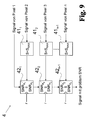
- the TDI-combined measured value calculation is to be performed in hardware, this can be done, for example, in a measured-value calculation unit 4 in accordance with the method described in FIG Fig. 10 shown block diagram can be realized.
- the illustrated hardware concept processes outputs 21 from signal preprocessing chains 1 of detectors 11 (eg, pixels of a sensor array) according to embodiment 3) of the invention.
- the adders 44 1 to 44 n-1 combine all (already weighted) signals originating from a target object 3 and thus provide the final result for the target object 3 under consideration. Multiplication and addition can take place either analogously or digitally.
- the resulting pipeline must be adjusted in its flow rate exactly the movement of the individual used for TDI calculation detectors 11 via one and the same target object 3. This boundary condition is in Fig. 10 drawn as supplied by the detectors 11 pixel clock r.
- Fig. 11 realized in a sketched block diagram for a hardware implementation of a measured value calculation unit 4.
- the flow chart of Fig. 10 extended to the effect that the signal level of the first detector 11 (signal of pixel 1) is controlled by means of a circuit 45 provided therefor, the amplifiers 46 of the subsequent detectors 11 (pixels 2 to n).
- the registers 47 are provided.
- the set gain must be taken into account by the respective multiplier 43. Therefore, the set gain is provided to the multiplier 43 as an input parameter. Multiplication and addition can be done both analogue and digital.
- the ADC 14 of the signal pre-processing chain 1 may be integrated into the amplifiers 46.
- FIG. 12 One possible software-based implementation of embodiment 3) of the invention is in Fig. 12 shown.
- the program flow diagram shown there starts with the initialization of the required memory and weight matrices. After reading the Signals from all detectors 11 into a signal matrix, the elements of the signal matrix are multiplied by the corresponding elements of the weight matrix and stored in a weighted signal matrix. This weighted signal matrix is added element by element to the existing memory matrix. Finally, the last (mth) line of the memory matrix is output. This output represents the result (as a weighted TDI calculation) in the sense of embodiment 3) of the invention. After the output of the last line of the memory matrix, all other lines of the memory matrix are shifted down one line or buffered. Thereafter, the first row of the memory array is initialized with zeros to be available again for the next read in and to process the sequence signals in the same way.
Applications Claiming Priority (1)
| Application Number | Priority Date | Filing Date | Title |
|---|---|---|---|
| DE102006057726A DE102006057726B4 (de) | 2006-12-02 | 2006-12-02 | Verfahren zur Messung elektromagnetischer Strahlung in Instrumenten der Luft- und Raumfahrt |
Publications (1)
| Publication Number | Publication Date |
|---|---|
| EP1928167A1 true EP1928167A1 (fr) | 2008-06-04 |
Family
ID=39100377
Family Applications (1)
| Application Number | Title | Priority Date | Filing Date |
|---|---|---|---|
| EP07023117A Withdrawn EP1928167A1 (fr) | 2006-12-02 | 2007-11-29 | Procédé de mesure du rayonnement électromagnétique dans les instruments de l'aéronautique et l'aérospatiale |
Country Status (2)
| Country | Link |
|---|---|
| EP (1) | EP1928167A1 (fr) |
| DE (1) | DE102006057726B4 (fr) |
Cited By (2)
| Publication number | Priority date | Publication date | Assignee | Title |
|---|---|---|---|---|
| WO2013093035A1 (fr) | 2011-12-22 | 2013-06-27 | Radisens Diagnostics Ltd. | Système et procédé pour la détection de luminescence polychrome à large portée dynamique instantanée à haute résolution d'échantillons biologiques dans un système microfluidique |
| LU92665B1 (de) * | 2015-02-24 | 2016-08-25 | Leica Microsystems | Verfahren zur verbesserung des dynamikbereichs einer vorrichtung zum detektieren von licht |
Families Citing this family (1)
| Publication number | Priority date | Publication date | Assignee | Title |
|---|---|---|---|---|
| DE102017208041A1 (de) * | 2017-05-12 | 2018-11-15 | Deutsches Zentrum für Luft- und Raumfahrt e.V. | TDI-Zeilendetektor |
Citations (4)
| Publication number | Priority date | Publication date | Assignee | Title |
|---|---|---|---|---|
| US20010007473A1 (en) * | 2000-01-07 | 2001-07-12 | Dynacolor, Inc. | Imaging method and apparatus for generating an output image with a wide dynamic range |
| WO2004036160A1 (fr) * | 2002-10-10 | 2004-04-29 | Institut für Physikalische Hochtechnologie e.V. | Spectrometre haute resolution |
| DE10307744A1 (de) * | 2003-02-24 | 2004-09-02 | Carl Zeiss Jena Gmbh | Verfahren zur Bestimmung der Intensitätswerte elektromagnetischer Strahlung |
| US20060007498A1 (en) * | 2004-07-07 | 2006-01-12 | Eastman Kodak Company | Extended dynamic range imaging system |
Family Cites Families (7)
| Publication number | Priority date | Publication date | Assignee | Title |
|---|---|---|---|---|
| US5101108A (en) * | 1988-12-14 | 1992-03-31 | Hughes Aircraft Company | Split dynamic range using dual array sensor chip assembly |
| DE19638693C2 (de) * | 1996-09-20 | 1998-12-17 | Fraunhofer Ges Forschung | Photodetektor und Farbfilter unter Verwendung eines Photodetektors |
| US6850278B1 (en) * | 1998-11-27 | 2005-02-01 | Canon Kabushiki Kaisha | Solid-state image pickup apparatus |
| US7382407B2 (en) * | 2002-08-29 | 2008-06-03 | Micron Technology, Inc. | High intrascene dynamic range NTSC and PAL imager |
| US7026596B2 (en) * | 2003-10-30 | 2006-04-11 | Micron Technology, Inc. | High-low sensitivity pixel |
| US7983867B2 (en) * | 2004-06-15 | 2011-07-19 | Varian Medical Systems, Inc. | Multi-gain data processing |
| JP4289244B2 (ja) * | 2004-07-16 | 2009-07-01 | ソニー株式会社 | 画像処理方法並びに物理量分布検知の半導体装置および電子機器 |
-
2006
- 2006-12-02 DE DE102006057726A patent/DE102006057726B4/de not_active Expired - Fee Related
-
2007
- 2007-11-29 EP EP07023117A patent/EP1928167A1/fr not_active Withdrawn
Patent Citations (4)
| Publication number | Priority date | Publication date | Assignee | Title |
|---|---|---|---|---|
| US20010007473A1 (en) * | 2000-01-07 | 2001-07-12 | Dynacolor, Inc. | Imaging method and apparatus for generating an output image with a wide dynamic range |
| WO2004036160A1 (fr) * | 2002-10-10 | 2004-04-29 | Institut für Physikalische Hochtechnologie e.V. | Spectrometre haute resolution |
| DE10307744A1 (de) * | 2003-02-24 | 2004-09-02 | Carl Zeiss Jena Gmbh | Verfahren zur Bestimmung der Intensitätswerte elektromagnetischer Strahlung |
| US20060007498A1 (en) * | 2004-07-07 | 2006-01-12 | Eastman Kodak Company | Extended dynamic range imaging system |
Non-Patent Citations (2)
| Title |
|---|
| E.L. DERENIAK; G.D. BOREMAN: "Infrared Detector Systems", 1996, JOHN WILEY & SONS, article "Serial Scan with Time Delay and Integration", pages: 491 - 493 |
| NAYAR S K ET AL: "High Dynamic Range Imaging: Spatially Varying Pixel Exposures", PROCEEDINGS 2000 IEEE CONFERENCE ON COMPUTER VISION AND PATTERN RECOGNITION. CVPR 2000. HILTON HEAD ISLAND, SC, JUNE 13-15, 2000, PROCEEDINGS OF THE IEEE COMPUTER CONFERENCE ON COMPUTER VISION AND PATTERN RECOGNITION, LOS ALAMITOS, CA : IEEE COMP. SO, vol. VOL. 1 OF 2, 13 June 2000 (2000-06-13), pages 472 - 479, XP002236923, ISBN: 0-7803-6527-5 * |
Cited By (5)
| Publication number | Priority date | Publication date | Assignee | Title |
|---|---|---|---|---|
| WO2013093035A1 (fr) | 2011-12-22 | 2013-06-27 | Radisens Diagnostics Ltd. | Système et procédé pour la détection de luminescence polychrome à large portée dynamique instantanée à haute résolution d'échantillons biologiques dans un système microfluidique |
| US9518925B2 (en) | 2011-12-22 | 2016-12-13 | Radisens Diagnostics Limited | High resolution, wide dynamic range microfluidic detection system |
| LU92665B1 (de) * | 2015-02-24 | 2016-08-25 | Leica Microsystems | Verfahren zur verbesserung des dynamikbereichs einer vorrichtung zum detektieren von licht |
| WO2016135178A1 (fr) * | 2015-02-24 | 2016-09-01 | Leica Microsystems Cms Gmbh | Procédé permettant d'améliorer la plage dynamique d'un dispositif de photodétection |
| US10488251B2 (en) | 2015-02-24 | 2019-11-26 | Leica Microsystems Cms Gmbh | Method for improving the dynamic range of a device for detecting light |
Also Published As
| Publication number | Publication date |
|---|---|
| DE102006057726B4 (de) | 2008-12-04 |
| DE102006057726A1 (de) | 2008-06-05 |
Similar Documents
| Publication | Publication Date | Title |
|---|---|---|
| EP0029569B1 (fr) | Procédé et dispositif de correction de la distorsion spatiale dans une caméra à scintillation | |
| EP0029244A1 (fr) | Procédé et dispositif de correction des irrégularités dans la réponse en énergie d'une caméra à scintillation | |
| DE3026897A1 (de) | Anordnung fuer differenzbildbestimmung | |
| EP0974226B1 (fr) | Detecteur d'images a pluralite de zones detectrices de pixels | |
| DE102010023166A1 (de) | Wärmebildkamera | |
| EP1346561B1 (fr) | Procede et dispositif de production d'images utilisant plusieurs temps d'exposition | |
| EP1301031A1 (fr) | Méthode de correction des charactéristiques de transfert différentes de capteurs d' images | |
| DE3836280C1 (fr) | ||
| DE102006057726B4 (de) | Verfahren zur Messung elektromagnetischer Strahlung in Instrumenten der Luft- und Raumfahrt | |
| DE10135427A1 (de) | Flächenhafter Bilddetektor für elektromagnetische Strahlen, insbesondere Röntgenstrahlen | |
| EP1312938A2 (fr) | Elément de détection de rayonnement | |
| EP3591962B1 (fr) | Compensation du bruit à motif fixe d'un capteur d'image | |
| DE19860036C1 (de) | Verfahren zum Reduzieren von spalten- oder zeilenkorreliertem bzw. teilspalten- oder teilzeilenkorreliertem Rauschen bei einem digitalen Bildsensor sowie Vorrichtung zur Aufnahme von Strahlungsbildern | |
| WO1998019454A1 (fr) | Procede de detection d'un signal d'image | |
| EP0558116B1 (fr) | Procédé pour radiographies et dispositif approprié | |
| EP3524925A1 (fr) | Procédé de détermination des facteurs de correction de courbes caractéristiques d'un détecteur matriciel de représentation dans la plage spectrale infrarouge | |
| DE102012205051A1 (de) | Verfahren zur Reduzierung von Direct-Hit-Artefakten und Röntgeneinrichtung | |
| EP0550830A1 (fr) | Montage pour le traitement des signaux d'un détecteur semi-conducteur | |
| DE102013109020A1 (de) | Streulichtreferenzpixel | |
| DE102010010447B4 (de) | Verfahren zum Bereitstellen von Bilddaten | |
| DE102004016585B4 (de) | Verfahren zur Rauschkorrektur bei einem Flachbilddetektor | |
| DE3432469A1 (de) | Verfahren und vorrichtungen zum auslesen eines optoelektrischen detektors | |
| EP0733293B1 (fr) | Procede de determination du niveau de bruit et detecteur du niveau de bruit | |
| DE10117833C1 (de) | Verfahren und Vorrichtung zur FPN-Korrektur von Bildsignalen | |
| EP3222033B1 (fr) | Procédé de détermination de la différence du comportement de transmission d'un ou de tous les points d'image d'un système de prise d'images |
Legal Events
| Date | Code | Title | Description |
|---|---|---|---|
| PUAI | Public reference made under article 153(3) epc to a published international application that has entered the european phase |
Free format text: ORIGINAL CODE: 0009012 |
|
| AK | Designated contracting states |
Kind code of ref document: A1 Designated state(s): AT BE BG CH CY CZ DE DK EE ES FI FR GB GR HU IE IS IT LI LT LU LV MC MT NL PL PT RO SE SI SK TR |
|
| AX | Request for extension of the european patent |
Extension state: AL BA HR MK RS |
|
| 17P | Request for examination filed |
Effective date: 20081105 |
|
| 17Q | First examination report despatched |
Effective date: 20081205 |
|
| AKX | Designation fees paid |
Designated state(s): AT BE BG CH CY CZ DE DK EE ES FI FR GB GR HU IE IS IT LI LT LU LV MC MT NL PL PT RO SE SI SK TR |
|
| STAA | Information on the status of an ep patent application or granted ep patent |
Free format text: STATUS: THE APPLICATION IS DEEMED TO BE WITHDRAWN |
|
| 18D | Application deemed to be withdrawn |
Effective date: 20130228 |