EP1928042A2 - Prismatische dosenförmige wiederaufladbare Lithium-Ionenbatterie - Google Patents
Prismatische dosenförmige wiederaufladbare Lithium-Ionenbatterie Download PDFInfo
- Publication number
- EP1928042A2 EP1928042A2 EP07119065A EP07119065A EP1928042A2 EP 1928042 A2 EP1928042 A2 EP 1928042A2 EP 07119065 A EP07119065 A EP 07119065A EP 07119065 A EP07119065 A EP 07119065A EP 1928042 A2 EP1928042 A2 EP 1928042A2
- Authority
- EP
- European Patent Office
- Prior art keywords
- prismatic
- distortion prevention
- lithium ion
- rechargeable battery
- inverted
- Prior art date
- Legal status (The legal status is an assumption and is not a legal conclusion. Google has not performed a legal analysis and makes no representation as to the accuracy of the status listed.)
- Granted
Links
Images


Classifications
-
- H—ELECTRICITY
- H01—ELECTRIC ELEMENTS
- H01M—PROCESSES OR MEANS, e.g. BATTERIES, FOR THE DIRECT CONVERSION OF CHEMICAL ENERGY INTO ELECTRICAL ENERGY
- H01M10/00—Secondary cells; Manufacture thereof
- H01M10/05—Accumulators with non-aqueous electrolyte
- H01M10/052—Li-accumulators
- H01M10/0525—Rocking-chair batteries, i.e. batteries with lithium insertion or intercalation in both electrodes; Lithium-ion batteries
-
- H—ELECTRICITY
- H01—ELECTRIC ELEMENTS
- H01M—PROCESSES OR MEANS, e.g. BATTERIES, FOR THE DIRECT CONVERSION OF CHEMICAL ENERGY INTO ELECTRICAL ENERGY
- H01M50/00—Constructional details or processes of manufacture of the non-active parts of electrochemical cells other than fuel cells, e.g. hybrid cells
- H01M50/10—Primary casings; Jackets or wrappings
- H01M50/102—Primary casings; Jackets or wrappings characterised by their shape or physical structure
- H01M50/103—Primary casings; Jackets or wrappings characterised by their shape or physical structure prismatic or rectangular
-
- H—ELECTRICITY
- H01—ELECTRIC ELEMENTS
- H01M—PROCESSES OR MEANS, e.g. BATTERIES, FOR THE DIRECT CONVERSION OF CHEMICAL ENERGY INTO ELECTRICAL ENERGY
- H01M50/00—Constructional details or processes of manufacture of the non-active parts of electrochemical cells other than fuel cells, e.g. hybrid cells
- H01M50/10—Primary casings; Jackets or wrappings
- H01M50/147—Lids or covers
-
- H—ELECTRICITY
- H01—ELECTRIC ELEMENTS
- H01M—PROCESSES OR MEANS, e.g. BATTERIES, FOR THE DIRECT CONVERSION OF CHEMICAL ENERGY INTO ELECTRICAL ENERGY
- H01M50/00—Constructional details or processes of manufacture of the non-active parts of electrochemical cells other than fuel cells, e.g. hybrid cells
- H01M50/30—Arrangements for facilitating escape of gases
- H01M50/342—Non-re-sealable arrangements
- H01M50/3425—Non-re-sealable arrangements in the form of rupturable membranes or weakened parts, e.g. pierced with the aid of a sharp member
-
- Y—GENERAL TAGGING OF NEW TECHNOLOGICAL DEVELOPMENTS; GENERAL TAGGING OF CROSS-SECTIONAL TECHNOLOGIES SPANNING OVER SEVERAL SECTIONS OF THE IPC; TECHNICAL SUBJECTS COVERED BY FORMER USPC CROSS-REFERENCE ART COLLECTIONS [XRACs] AND DIGESTS
- Y02—TECHNOLOGIES OR APPLICATIONS FOR MITIGATION OR ADAPTATION AGAINST CLIMATE CHANGE
- Y02E—REDUCTION OF GREENHOUSE GAS [GHG] EMISSIONS, RELATED TO ENERGY GENERATION, TRANSMISSION OR DISTRIBUTION
- Y02E60/00—Enabling technologies; Technologies with a potential or indirect contribution to GHG emissions mitigation
- Y02E60/10—Energy storage using batteries
Definitions
- the present invention relates to a prismatic can type lithium ion battery and, more particularly, to a prismatic can type lithium ion rechargeable battery that improves the operational reliability of a safety vent in response to an increased internal pressure.
- Batteries are used as a power supply of such portable electronic devices, in which secondary batteries are more cost effective than primary batteries, since the secondary batteries can be recharged and reused. Accordingly, various secondary batteries of small size and high capacity have been developed and widely used. Especially, lithium second batteries are widely used as a power supply of portable electronic devices, since they can accumulate a lot of energy for their volume and weight.
- a pouch type lithium rechargeable battery has been manufactured recently, a can type lithium rechargeable battery in which an electrode assembly including a positive electrode, a negative electrode, and a separator disposed between the two electrodes are enclosed along with an electrolyte in a metal can has been manufactured prevalently.
- Such a can type rechargeable battery can be classified into a cylinder type battery designed for improving the capacity and a prismatic battery designed in a small thickness for reducing its volume and increasing the portability.
- a lithium ion rechargeable battery is, generally, made of a positive electrode active material for forming a positive electrode and a negative electrode active material for forming a negative electrode.
- a positive electrode active material LiCoO 2 (lithium cobalt oxide), LiNiO 2 (lithium nickel oxide), Li 2 MnO 4 (lithium manganese oxide), a lithium salt of an oxide solid solution, including at least two selected from the group consisting of cobalt, nickel and manganese that enable intercalation and deintercalation of lithium ions, is used.
- the negative electrode active material various carbon structures that also enable intercalation and deintercalation of lithium ions are used.
- These two electrode active materials are made in the form of slurry including binder, solvent, conductor and the like, and coated on the surface of current collectors, thus forming the two electrodes.
- a separator for preventing electric contact between the two electrodes is disposed therebetween and an electrolyte is necessarily established between the two electrodes to enable current flow therein based on lithium ions.
- the lithium battery has a high charge/discharge operation voltage in which side reactions between electrolyte and electrode materials may occur. Side reactions between electrolyte and electrode materials may occur at high temperature caused by the heat when operating. As a result, gas is generated to increase the internal pressure of the battery, thus expanding the battery. Moreover, in the case of a graphite negative electrode, its volume may be increased when intercalating lithium ions to charge, which results in expansion of the electrode assembly and the battery.
- the gas generation and the internal pressure increase of the battery result mainly from unusual reactions in the battery and, if such unusual reactions continue to occur over a specific level, the battery may explode, which, of course, decreases the safety of the battery. Accordingly, in preparation for the case where the internal pressure is increased over a specific level, a safety device such as a safety vent is established to intercept the operation of the battery using the increased internal pressure.
- the swelling of the can also makes it difficult for the cell having the swelled can to be adopted or inserted in a electric/electronic devices.
- the swelling of a can, along with the change of the shape of the can should be prevented and a safety vent should operate in an accurate range of internal pres sure.
- the present invention may provide a prismatic can type lithium ion rechargeable battery having a structure for solving the safety problems in forming a safety vent as described above.
- Another object of the present invention is to provide a prismatic can type lithium ion rechargeable battery that may burst in response to gas overpressure by concentrating the distortion forces generated in the can of the prismatic battery caused by the increased internal pressure, thus improving the safety of the lithium ion rechargeable battery.
- a prismatic can type lithium ion rechargeable battery including an electrode assembly for producing electricity, a prismatic can for accommodating the electrode assembly, and a cap assembly including a cap plate that closes the opening of the top surface of the prismatic can.
- the prismatic can has a top surface having an opening, a bottom surface, and a maximum area surface.
- the maximum area surface includes a distortion prevention portion, and a weakened portion formed outside a periphery of the distortion prevention portion.
- the weakened portion may be formed as a line formed outside a periphery of the distortion prevention portion.
- the distortion prevention portion may be formed as a line that is substantially parallel to a first direction that extends from the top surface to the bottom surface, or the distortion prevention portion is formed as a line that is oblique to the first direction.
- a notch may be formed along the line of the weakened portion.
- the line of the weakened portion can be formed as a curved line that curves along the periphery of the distortion prevention portion.
- the weakened portion can be formed closer to the cap assembly than a center of the maximum area surface, the weakened portion formed substantially parallel to the top surface, and the distortion prevention portion can be formed in a line shape that is substantially parallel to a first direction that extends from the top surface to the bottom surface, the distortion prevention portion having a prominence or a depression.
- the weakened portion can be formed in an inverted U-shape, the top of the inverted U-shaped weakened portion being closer to the cap assembly than the bottom of the inverted U-shaped weakened portion, and a first end of the line shaped distortion prevention portion may be surrounded by the inverted U-shaped weakened portion in a manner that the line shaped distortion prevention portion extends from the first end towards the bottom surface through the bottom of the inverted U-shaped weakened portion.
- the weakened portion can be formed closer to the cap assembly than a center of the maximum area surface, the weakened portion formed substantially parallel to the top surface, and the distortion prevention portion can be formed in an open rectangular shape.
- the weakened portion can be formed in an inverted U-shape, the top of the inverted U-shape being closer to the cap assembly than the bottom of the inverted U-shape, and the open rectangular shaped distortion prevention portion may have a shorter side and a longer side, the shorter side of the open rectangular shaped distortion prevention portion being surrounded by the inverted U-shaped weakened portion in a manner that the longer side of the open rectangular shaped distortion prevention portion extends along a first direction, which extends from the top surface to the bottom surface, towards the bottom surface through the bottom of the inverted U-shape.
- the distortion prevention portion may have a portion selected from the group consisting of a stepped portion, a thickened portion, and a partially bent portion on the maximum area surface.
- the weakened portion can be formed closer to the cap assembly than a center of the maximum area surface, the weakened portion formed substantially parallel to the top surface, and the distortion prevention portion can be formed as an open lozenge.
- the weakened portion may be formed in an inverted V-shape, the top of the inverted V-shape being closer to the cap assembly than the bottom of the inverted U-shape, and a corner of the open lozenge of the distortion prevention portion may be surrounded by the inverted U-shaped weakened portion.
- the distortion prevention portion can be formed in an open rectangular shape, the open rectangular shaped distortion prevention structure having a shorter side and a longer side, the longer side of the open rectangular shaped distortion prevention portion extending along a first direction, which extends from the top surface to the bottom surface, towards the bottom surface, and the weakened portion can be formed to surround a corner of the open rectangular shaped distortion prevention portion, the weakened portion being formed closer to the cap assembly than a center of the maximum area surface.
- the weakened portion may act as a safety vent rupturable in response to gaseous overpressure in the can.
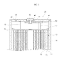
- FIG. 1 is the top front sectional view illustrating a structure of an electrode assembly, a can and a cap assembly in a prismatic can type lithium ion rechargeable battery in accordance with a exemplary embodiment of the present invention.
- the lithium rechargeable battery is fabricated by accommodating an electrode assembly 12 including a positive electrode 13, a negative electrode 15 and a separator 14 in a can 10 along with an electrolyte and then sealing up the upper end of the can 10 with a cap assembly 20.
- Can 10 has a top surface having an opening, a bottom surface, and the maximum area surface.
- the cap assembly 20 includes a cap plate 40, an insulating plate 50, a terminal plate 60 and an electrode terminal 30. The cap assembly 20 seals up the opening of can 10 in combination with an insulating case 70.
- the electrode terminal 30 is inserted into a terminal through-hole 41 formed in the middle of the cap plate 40.
- a tube type gasket 46 is connected to the outer circumference of the electrode terminal 30 to insulate the electrode terminal 30 and the cap plate 40.
- an electrolyte is injected through an electrolyte injection hole 42 and the electrolyte injection hole 42 is sealed tightly by a plug 43.
- the electrode terminal 30 is connected with a negative electrode tab 17 of the negative electrode 15 or a positive electrode tab 16 of the positive electrode 13 to act as a negative electrode terminal or a positive electrode terminal.
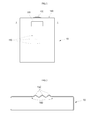
- FIG. 2 is a front view illustrating a prismatic can of the lithium ion battery in accordance with the present invention, in which a weakened portion constituting a safety vent and a distortion prevention portion are established in the middle of the maximum area surface.
- FIG. 3 is a cross sectional view, cut along with line A-A, depicting a can wall, on which the safety vent and the distortion prevention portion of FIG. 2 are formed together.
- FIG. 4 is a longitudinal sectional view of a cap plate and a can wall for illustrating how the weakened portion of the safety vent is fractured in accordance with the exemplary embodiment of the present invention.
- a safety vent 160 and a distortion prevention portion 150 are established in the middle of the maximum area surface of a rectangular parallelepiped can 10.
- the rectangular parallelepiped has six faces, and the maximum area surface means the face that has the largest surface area among the six faces.
- the safety vent 160 is positioned spaced 5mm apart from the central portion of the upside of the maximum area surface.
- the central portion corresponding to the middle portion when dividing the upside equally by three, i.e., the central portion takes the width of one third in the whole upside of the maximum area surface connected with a cap plate 140 depicted in the form of the sectional view only in this figure.
- the safety vent 160 includes an inverted U-shaped ( ⁇ -shaped) weakened portion.
- the inverted U-shape has a open portion on the bottom, and closed portion on the top.
- the open portion of the ⁇ -shaped weakened portion is arranged facing toward the center or bottom of the can 10. Accordingly, the upper horizontal portion (closed portion) of the ⁇ -shaped weakened portion of the safety vent 160 is parallel to the upper side of the maximum area surface.
- the weakened portion instead of the horizontal weak area, it is possible to form the weakened portion in the form of a semicircle or a parabola protruding toward the upper side of the maximum area surface, or a ⁇ -shaped weakened portion is available.
- the distortion prevention portion 150 including three consecutive hills (ridges) is established from a portion spaced about 1mm apart from the weakened portion in the up and down direction (in the longitudinal direction) of the battery.
- the length of the distortion prevention portion 150 extends over the center of the maximum area surface of the prismatic battery. Accordingly, the top of the hills (ridges) established longitudinally is parallel to the vertical portions of the ⁇ -shaped weakened portion arranged longitudinally. Since the largest distortion will occur along with the central axis in the longitudinal direction over the maximum area surface, it is desirable that the middle hill, among the three hills constituting the distortion prevention portion 150, be arranged along with the central axis of the maximum area surface and the other hills be arranged symmetrically based on the central axis.
- the weakened portion of the safety vent 160 has notches having a thickness of 0.05mm or less, compared with the other portions of the can wall so that the weakened portion is more readily fractured than the other portions. It can be easily understood that the hill structure of the distortion prevention portion 150 may not be more readily bent in the longitudinal direction than the other portions of the wall of the can 10, since the thickness of the wall of the can 10 is formed windingly without special variations compared with the other portions thereof.
- the prismatic can of a rectangular parallelepiped shape has characteristics in that, if gas is generated therein or the electrode assembly is expanded due to the charging, the maximum area surface may become swollen externally and the other surfaces are likely to swell internally as it is generally expanded by the increased internal pressure. In the maximum area surface, although the extent that it is distorted partially are different, the central area swells, whereas, its environs are not expanded since they are connected with the other surfaces as depicted in FIG. 4.
- the surface of the cap plate 140 which is the top of the battery or the portion connected with the bottom, hardly swell in the thickness direction of the battery. In the central portion of the maximum area surface, an expansion force acts externally in the thickness direction of the battery.
- the wall of the maximum area surface receives forces that act to pull the wall downward and in both side directions in the bottom of the can 10 and the connection portion of the cap plate 140 that are both ends and also receives forces that act to push the wall upward in the center.
- the wall of the maximum area surface receives forces that act to bend the wall in the longitudinal direction.
- the hill (ridge) or valley structure formed in the longitudinal direction resists the bending forces by the reaction of the internal pressure and produces forces that act to maintain the plane shape of the maximum area surface wall.
- the forces acting to bend the wall in the longitudinal direction by the internal pressure and the forces acting to maintaining the plane shape of the maximum area surface wall react most strongly in opposite direction with each other in the end of the distortion prevention portion 150. Accordingly, if a fracture line of a notch shape is established in the end of the distortion prevention portion 150, it is readily fractured, thus acting as a safety vent 160.
- the force applied to the weakened portion of the safety vent 160 is considered as similar to the force that acts on an action point of a lever.
- a virtual connection line connecting two end points forming the opening portion of the ⁇ -shaped weakened portion functions as a support point of a lever and the horizontal weakened portion forming the closed portion of the ⁇ -shaped weakened portion becomes an action point of a lever.
- the spacing distance between the horizontal weakened portion and the virtual connection line connecting the two end points of the opening portion functions as a distance between the action point and the support point and, accordingly, the force acting to bend the wall is amplified in the weakened portion that is the action point.
- the weakened portion of the ⁇ -shaped safety vent 160 may be fractured during the formation thereof, since it is very vulnerable to an internal pressure or an external impact. Accordingly, it is desirable that the distortion prevention portion 150 be formed spaced apart from the upper horizontal portion of the weakened portion at regular intervals.
- FIG. 5 is a front view depicting a state where a safety vent is established by considering a concept of a maximum distortion portion on the maximum area surface of the prismatic can of FIG. 2.
- the general structure of the safety vent 160 and the distortion prevention portion 150 are the same as the exemplary embodiment of FIG. 2, however, the safety vent 160 has a characteristic in that it is established by considering the maximum distortion portion on the maximum area surface.
- the maximum distortion portion is not marked externally in the process of forming a can, but obtained through a simulation or an actual experiment.
- the maximum distortion portion is directed to a portion where a relatively high distortion may occur when causing a swelling distortion by increasing the pressure in a case of the battery, in which a prismatic can is sealed up with a cap assembly, and it has a shape of a connected line in the vicinity of each side or a shape of a belt having a regular width.
- a schematic shape of the maximum distortion portion is nearly a smooth curve like the dotted line marked in FIG. 6, which can be seen as a shape of a line segment curved at least one to be symmetric.
- the horizontal cut line that is directed to the closed portion in the middle of the ⁇ -shaped safety vent 160 is located inclined 5mm, for example, from the maximum distortion portion to the side, and the distortion prevention portion 150 is arranged to intersect the maximum distortion portion.
- the end of the distortion prevention portion 150 and the horizontal weakened portion are established spaced about 0.5m to 1mm apart from each other to prevent the burst of the horizontal weakened portion in the process of forming the safety vent 160 or the distortion prevention portion 150.
- the spacing distance between the horizontal portion of the weakened portion and the maximum distortion portion is set large, the distortion force caused by the internal pressure and the force for preventing the distortion by the distortion prevention portion 150 may be dispersed over the spacing distance, thus not readily causing the burst of the horizontal weak area.
- Distortion acceleration portions 170 may be established at both sides of the safety vent 160 along with the maximum distortion portion.
- the distortion acceleration portions are located at positions substantially identical or close to the maximum distortion portion. Accordingly, if they are formed to be readily folded when distortions are generated by the internal pressure of the can, the forces for folding the wall of the can 10 are concentrated on the line connecting the distortion acceleration portions 170 at both sides of the safety vent 160.
- any structure, which is readily folded like the distortion acceleration portion is not provided on the line (e.g., line A-A in FIG. 5) connecting the distortion acceleration portions 170. Rather, the distortion prevention portion 150 for preventing the distortion is intersected therebetween, therefore, the force acting to the weakened portion of the safety vent 160 may be more concentrated through the distortion prevention portion 150.
- FIGS. 7 to 11 illustrate other exemplary embodiments in other aspects of the present invention.
- the weakened portion is composed of a horizontal weakened portion 165 only, and two lines 155 which are formed by shaping the wall of the can are provided below the horizontal weak area 165.
- the lines 155 function as the distortion prevention portion 150 of FIG. 5.
- the lines 155 are provided in such a manner that wrinkles are formed on the wall or partially stepped surfaces are formed using a press frame.
- the horizontal weakened portion 165 is established at a position more adjacent to the cap plate 140 constituting the cap assembly than the maximum area surface of the prismatic can 10 to intersect a long axis (A) of the maximum area surface.
- the line shaped distortion prevention portion 155 can be formed to be substantially parallel to a first direction that extends from the top surface to the bottom surface, or the distortion prevention portion can be formed as a line that is oblique to the first direction.
- the weakened portion is composed of a horizontal weakened portion 175 only, and a rectangular dimple 180 is established below the horizontal weak areas 175 long in the longitudinal direction in order to work as the distortion prevention portion.
- a ⁇ -shaped weakened portion 260 of is composed of a horizontal portion 265 and a vertical portion 267, and a rectangular dimple 280 functioning as the distortion prevention portion is established long in the parallel direction to the long axis.
- a short side of the rectangular dimple 280 is positioned more adjacent to the cap plate 140 constituting the cap assembly than a virtual line 269 connecting two ends of the vertical weak areas 267 which constitutes the opening portion of the ⁇ -shaped weakened portion 260 to be surrounded by the weakened portion 260.
- a weakened portion 360 is positioned more adjacent to the portion connected with the cap plate 140 than the center of the maximum area surface to intersect the long axis of the maximum area surface.
- the distortion prevention portion is composed of a lozenge-shaped dimple 380 formed long in the parallel direction to the long axis.
- the weakened portion 360 is arranged in a V shape in that the closed portion faces toward the cap plate 140, and the upper corner of the lozenge-shaped dimple 380 is positioned more adjacent to the cap plate 140 than a virtual line 369 connecting two ends constituting the opening portion of the V-shaped weakened portion 360 to be surrounded by the weakened portion 360.
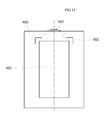
- the distortion prevention portion is composed of a rectangular dimple 480 formed on the wall of the maximum area surface long in the parallel direction to the long axis.
- a weakened portion 460 is formed in the shape of a line segment curved on the outside of two upper corners 460 of the cap plate 140 of the rectangular dimple to surround the two upper corners.
- the dimples of the exemplary embodiments depicted in FIGS. 8 to 11 constitute the distortion prevention portion and prevent the maximum area surface from being expanded during the swelling distortion and, simultaneously, function as a lever like the distortion prevention portion of FIG. 5 to amplify the forces for bursting the weakened portion that forms the safety vent.
- the distortion prevention portion can be a portion such as a stepped portion, a thickened portion, and a partially bent portion on the maximum area surface.
- the forces acting from the safety vent formed on the maximum area surface to both sides of the weak area, generated when the can distortion of the prismatic battery is caused by the internal pressure, are concentrated on the weakened portion to be readily burst, thus preventing the explosion of the battery or the firing to improve the safety and reliability of the prismatic lithium ion battery.
Landscapes
- Chemical & Material Sciences (AREA)
- Chemical Kinetics & Catalysis (AREA)
- Electrochemistry (AREA)
- General Chemical & Material Sciences (AREA)
- Engineering & Computer Science (AREA)
- Materials Engineering (AREA)
- Manufacturing & Machinery (AREA)
- Sealing Battery Cases Or Jackets (AREA)
- Gas Exhaust Devices For Batteries (AREA)
- Secondary Cells (AREA)
Applications Claiming Priority (1)
| Application Number | Priority Date | Filing Date | Title |
|---|---|---|---|
| KR1020060103941A KR100833737B1 (ko) | 2006-10-25 | 2006-10-25 | 각형 리튬 이온 전지 |
Publications (3)
| Publication Number | Publication Date |
|---|---|
| EP1928042A2 true EP1928042A2 (de) | 2008-06-04 |
| EP1928042A3 EP1928042A3 (de) | 2008-06-11 |
| EP1928042B1 EP1928042B1 (de) | 2010-12-01 |
Family
ID=39205127
Family Applications (1)
| Application Number | Title | Priority Date | Filing Date |
|---|---|---|---|
| EP07119065A Not-in-force EP1928042B1 (de) | 2006-10-25 | 2007-10-23 | Prismatische dosenförmige wiederaufladbare Lithium-Ionenbatterie |
Country Status (5)
| Country | Link |
|---|---|
| US (1) | US20080102364A1 (de) |
| EP (1) | EP1928042B1 (de) |
| KR (1) | KR100833737B1 (de) |
| CN (1) | CN101170165B (de) |
| DE (1) | DE602007010885D1 (de) |
Cited By (2)
| Publication number | Priority date | Publication date | Assignee | Title |
|---|---|---|---|---|
| WO2012130631A1 (de) * | 2011-03-28 | 2012-10-04 | Robert Bosch Gmbh | Batteriezelle |
| DE102024109564A1 (de) | 2024-04-05 | 2025-10-09 | Audi Aktiengesellschaft | Gehäusebauteil für ein Zellgehäuse mit integriertem Zelltrennelement, Batteriezelle und Verfahren zum Herstellen einer Vorrichtung mit einem Zelltrennelement |
Families Citing this family (11)
| Publication number | Priority date | Publication date | Assignee | Title |
|---|---|---|---|---|
| EP2212941B1 (de) | 2007-11-21 | 2015-01-14 | LG Chem, Ltd. | Batteriemodul mit erhöhter sicherheit und mittelgrosse oder grosse batteriepackung damit |
| KR101350664B1 (ko) | 2008-04-03 | 2014-01-10 | 주식회사 엘지화학 | 안전성이 향상된 이차 전지 |
| EP2348557B1 (de) * | 2010-01-13 | 2013-07-03 | Samsung SDI Co., Ltd. | Sekundärbatterie |
| KR101527256B1 (ko) * | 2011-06-09 | 2015-06-08 | 주식회사 엘지화학 | 이차전지 |
| US9099692B2 (en) | 2012-11-07 | 2015-08-04 | Hyundai Motor Company | Rechargeable battery |
| KR102211368B1 (ko) * | 2014-05-09 | 2021-02-03 | 삼성에스디아이 주식회사 | 가요성 이차 전지 |
| KR102417637B1 (ko) * | 2015-10-02 | 2022-07-06 | 삼성에스디아이 주식회사 | 이차 전지 |
| JP6536354B2 (ja) * | 2015-11-02 | 2019-07-03 | 株式会社村田製作所 | 電池、電池パック、電子機器、電動車両、蓄電装置および電力システム |
| CN115117546A (zh) * | 2022-06-20 | 2022-09-27 | 中创新航科技股份有限公司 | 电池 |
| CN114899548A (zh) * | 2022-06-20 | 2022-08-12 | 中创新航科技股份有限公司 | 电池 |
| CN221226383U (zh) * | 2024-03-25 | 2024-06-25 | 宁德时代新能源科技股份有限公司 | 电池单体、电池和用电设备 |
Citations (4)
| Publication number | Priority date | Publication date | Assignee | Title |
|---|---|---|---|---|
| CA2165152A1 (en) | 1995-12-13 | 1997-06-14 | Allen Shkuratoff | Safety vent for a sealed prismatic electrical device |
| WO2002027819A1 (en) | 2000-09-29 | 2002-04-04 | Lg Chemical Co., Ltd. | Safety plate of secondary battery |
| JP2002237283A (ja) | 2001-02-08 | 2002-08-23 | Osaka Gas Co Ltd | 非水系二次電池 |
| EP1258931A1 (de) | 2000-02-18 | 2002-11-20 | Matsushita Electric Industrial Co., Ltd. | Sicherungsverfahren für rechteckige batterie und herstellungsverfahren dafür |
Family Cites Families (9)
| Publication number | Priority date | Publication date | Assignee | Title |
|---|---|---|---|---|
| US4803136A (en) * | 1985-09-30 | 1989-02-07 | Emerson Electric Co. | Method of manufacturing a safety vented container and product |
| US6159631A (en) * | 1998-08-27 | 2000-12-12 | Polystor Corporation | Overcharge safety vents on prismatic cells |
| JP2001126693A (ja) | 1999-10-25 | 2001-05-11 | Nec Mobile Energy Kk | 密閉型電池 |
| JP3725433B2 (ja) * | 2001-02-15 | 2005-12-14 | Necトーキン栃木株式会社 | 角型電池およびその製造方法 |
| JP3740048B2 (ja) * | 2001-10-12 | 2006-01-25 | 松下電器産業株式会社 | 電池缶およびそれを用いた電池 |
| KR20020042598A (ko) * | 2002-05-16 | 2002-06-05 | 이점호 | 이차전지 케이스의 안전판 |
| KR100576327B1 (ko) * | 2003-12-12 | 2006-05-03 | 주식회사 일광캔테크 | 이차전지케이스의 폭발방지구조 |
| KR100614381B1 (ko) * | 2004-07-29 | 2006-08-21 | 삼성에스디아이 주식회사 | 리튬 이온 이차 전지 |
| CN2757343Y (zh) * | 2004-11-16 | 2006-02-08 | 比亚迪股份有限公司 | 一种防爆安全电池 |
-
2006
- 2006-10-25 KR KR1020060103941A patent/KR100833737B1/ko not_active Expired - Fee Related
-
2007
- 2007-10-23 EP EP07119065A patent/EP1928042B1/de not_active Not-in-force
- 2007-10-23 DE DE602007010885T patent/DE602007010885D1/de active Active
- 2007-10-25 US US11/976,588 patent/US20080102364A1/en not_active Abandoned
- 2007-10-25 CN CN2007101634606A patent/CN101170165B/zh not_active Expired - Fee Related
Patent Citations (4)
| Publication number | Priority date | Publication date | Assignee | Title |
|---|---|---|---|---|
| CA2165152A1 (en) | 1995-12-13 | 1997-06-14 | Allen Shkuratoff | Safety vent for a sealed prismatic electrical device |
| EP1258931A1 (de) | 2000-02-18 | 2002-11-20 | Matsushita Electric Industrial Co., Ltd. | Sicherungsverfahren für rechteckige batterie und herstellungsverfahren dafür |
| WO2002027819A1 (en) | 2000-09-29 | 2002-04-04 | Lg Chemical Co., Ltd. | Safety plate of secondary battery |
| JP2002237283A (ja) | 2001-02-08 | 2002-08-23 | Osaka Gas Co Ltd | 非水系二次電池 |
Cited By (2)
| Publication number | Priority date | Publication date | Assignee | Title |
|---|---|---|---|---|
| WO2012130631A1 (de) * | 2011-03-28 | 2012-10-04 | Robert Bosch Gmbh | Batteriezelle |
| DE102024109564A1 (de) | 2024-04-05 | 2025-10-09 | Audi Aktiengesellschaft | Gehäusebauteil für ein Zellgehäuse mit integriertem Zelltrennelement, Batteriezelle und Verfahren zum Herstellen einer Vorrichtung mit einem Zelltrennelement |
Also Published As
| Publication number | Publication date |
|---|---|
| EP1928042B1 (de) | 2010-12-01 |
| CN101170165B (zh) | 2011-10-26 |
| DE602007010885D1 (de) | 2011-01-13 |
| US20080102364A1 (en) | 2008-05-01 |
| KR100833737B1 (ko) | 2008-05-29 |
| KR20080037199A (ko) | 2008-04-30 |
| EP1928042A3 (de) | 2008-06-11 |
| CN101170165A (zh) | 2008-04-30 |
Similar Documents
| Publication | Publication Date | Title |
|---|---|---|
| EP1928042B1 (de) | Prismatische dosenförmige wiederaufladbare Lithium-Ionenbatterie | |
| CN216213727U (zh) | 电池单体、电池以及用电装置 | |
| KR101201812B1 (ko) | 이차 전지 | |
| KR100551885B1 (ko) | 리튬 이온 2차 전지 | |
| CN100433408C (zh) | 密封方形电池 | |
| EP2450982B1 (de) | Batteriemodul | |
| CN103155225B (zh) | 新型结构的帽组件与利用该帽组件的圆筒形电池 | |
| CN114467225B (zh) | 电池模块、电池包以及使用电池作为电源的装置 | |
| JP5389368B2 (ja) | 密閉型電池 | |
| KR100914115B1 (ko) | 이차전지 | |
| WO2014119308A1 (ja) | 密閉型電池 | |
| WO2014119309A1 (ja) | 密閉型電池 | |
| CN120184500A (zh) | 二次电池和汽车 | |
| CN116565445B (zh) | 防爆阀、端盖组件及储能装置 | |
| CN217182356U (zh) | 端盖组件、电池单体、电池及用电装置 | |
| CN115832548B (zh) | 电池单体、电池以及用电装置 | |
| CN111384332B (zh) | 电池模组以及电池包 | |
| KR100898677B1 (ko) | 각형 리튬 이온 전지 | |
| EP2348557A1 (de) | Sekundärbatterie | |
| KR20210051733A (ko) | 파우치형 이차전지 및 이의 제조 방법 | |
| JP2004178820A (ja) | 電池用封口板 | |
| KR100601508B1 (ko) | 종압축에 대한 안전성이 향상된 이차 전지 | |
| EP2551934A1 (de) | Wiederaufladbare Batterie | |
| KR100646541B1 (ko) | 캔형 이차 전지 | |
| JP3956456B2 (ja) | 密閉型円筒形電池用防爆封口板 |
Legal Events
| Date | Code | Title | Description |
|---|---|---|---|
| PUAI | Public reference made under article 153(3) epc to a published international application that has entered the european phase |
Free format text: ORIGINAL CODE: 0009012 |
|
| PUAL | Search report despatched |
Free format text: ORIGINAL CODE: 0009013 |
|
| 17P | Request for examination filed |
Effective date: 20071023 |
|
| AK | Designated contracting states |
Kind code of ref document: A2 Designated state(s): AT BE BG CH CY CZ DE DK EE ES FI FR GB GR HU IE IS IT LI LT LU LV MC MT NL PL PT RO SE SI SK TR |
|
| AX | Request for extension of the european patent |
Extension state: AL BA HR MK RS |
|
| AK | Designated contracting states |
Kind code of ref document: A3 Designated state(s): AT BE BG CH CY CZ DE DK EE ES FI FR GB GR HU IE IS IT LI LT LU LV MC MT NL PL PT RO SE SI SK TR |
|
| AX | Request for extension of the european patent |
Extension state: AL BA HR MK RS |
|
| AKX | Designation fees paid |
Designated state(s): DE FR GB HU |
|
| RAP1 | Party data changed (applicant data changed or rights of an application transferred) |
Owner name: SAMSUNG SDI CO., LTD. |
|
| GRAP | Despatch of communication of intention to grant a patent |
Free format text: ORIGINAL CODE: EPIDOSNIGR1 |
|
| GRAS | Grant fee paid |
Free format text: ORIGINAL CODE: EPIDOSNIGR3 |
|
| GRAA | (expected) grant |
Free format text: ORIGINAL CODE: 0009210 |
|
| AK | Designated contracting states |
Kind code of ref document: B1 Designated state(s): DE FR GB HU |
|
| REG | Reference to a national code |
Ref country code: GB Ref legal event code: FG4D |
|
| REF | Corresponds to: |
Ref document number: 602007010885 Country of ref document: DE Date of ref document: 20110113 Kind code of ref document: P |
|
| PLBE | No opposition filed within time limit |
Free format text: ORIGINAL CODE: 0009261 |
|
| STAA | Information on the status of an ep patent application or granted ep patent |
Free format text: STATUS: NO OPPOSITION FILED WITHIN TIME LIMIT |
|
| 26N | No opposition filed |
Effective date: 20110902 |
|
| REG | Reference to a national code |
Ref country code: DE Ref legal event code: R097 Ref document number: 602007010885 Country of ref document: DE Effective date: 20110902 |
|
| PG25 | Lapsed in a contracting state [announced via postgrant information from national office to epo] |
Ref country code: HU Free format text: LAPSE BECAUSE OF FAILURE TO SUBMIT A TRANSLATION OF THE DESCRIPTION OR TO PAY THE FEE WITHIN THE PRESCRIBED TIME-LIMIT Effective date: 20101201 |
|
| REG | Reference to a national code |
Ref country code: FR Ref legal event code: PLFP Year of fee payment: 9 |
|
| PGFP | Annual fee paid to national office [announced via postgrant information from national office to epo] |
Ref country code: FR Payment date: 20150923 Year of fee payment: 9 |
|
| PGFP | Annual fee paid to national office [announced via postgrant information from national office to epo] |
Ref country code: GB Payment date: 20151021 Year of fee payment: 9 Ref country code: DE Payment date: 20151020 Year of fee payment: 9 |
|
| REG | Reference to a national code |
Ref country code: DE Ref legal event code: R119 Ref document number: 602007010885 Country of ref document: DE |
|
| GBPC | Gb: european patent ceased through non-payment of renewal fee |
Effective date: 20161023 |
|
| REG | Reference to a national code |
Ref country code: FR Ref legal event code: ST Effective date: 20170630 |
|
| PG25 | Lapsed in a contracting state [announced via postgrant information from national office to epo] |
Ref country code: FR Free format text: LAPSE BECAUSE OF NON-PAYMENT OF DUE FEES Effective date: 20161102 Ref country code: GB Free format text: LAPSE BECAUSE OF NON-PAYMENT OF DUE FEES Effective date: 20161023 Ref country code: DE Free format text: LAPSE BECAUSE OF NON-PAYMENT OF DUE FEES Effective date: 20170503 |